DESIGN AND DEVELOPMENT OF A THREE PHASE SHUNT ACTIVE POWER FILTER FOR HARMONICS
REDUCTION IN INDUSTRIAL USING MATLAB/SIMULINK
MUHAMAD NUR ARIF BIN BAHARUDIN
BACHELOR OF ELECTRICAL ENGINEERING (INDUSTRIAL POWER)
“ I hereby declare that I have read through this report entitle “Design And Development Of A Three Phase Shunt Active Power Filter For Harmonics Reduction In Industrial Using Matlab/Simulink” and found that has comply the partial fulfillment for awarding the degree
of Bachelor of Electrical Engineering (Industrial Power)”
Signature : ……….
Supervisor’s name : ……….
DESIGN AND DEVELOPMENT OF A THREE PHASE SHUNT ACTIVE POWER FILTER FOR HARMONICS REDUCTION IN INDUSTRIAL USING
MATLAB/SIMULINK
MUHAMAD NUR ARIF BIN BAHARUDIN
A report submitted in partial fulfillment of the requirements for the degree of Electrical Engineering (Industrial Power)
Faculty of Electrical Engineering
UNIVERSITI TEKNIKAL MALAYSIA MELAKA
I declare that this report entitle “Design And Development Of A Three Phase Shunt Active Power Filter For Harmonics Reduction In Industrial Using Matlab/Simulink” is the result of my own research except as cited in the references. The report has not been accepted for
any degree and is not concurrently submitted in candidature of any other degree.
Signature : ……….
Name : ……….
ACKNOWLEDGEMENT
Firstly, I would like to offer my gratitude to Allah S.W.T for the mercy and grace, I finally able to complete a report for the Final Year Project 2 (FYP2) based on the specified date.
Here, I would like to express my deepest appreciation and thank you to those who have helped me directly or indirectly in completing this project. In this opportunity, I would like to express my gratitude to Mr. Ir. Rosli Bin Omar as my project supervisor, who has helped me in completing this project and helped me to solve the problem in which I faced during this project. In addition, I wish to thank to Universiti Teknikal Malaysia Melaka in particular to all members of the committee for Final Year Project and all that are involved to implement this project properly. Finally I would like to show my appreciation to my parents because for their encouragement and moral support during my studies at the Universiti Teknikal Malaysia Melaka (UTeM).
ABSTRACT
ABSTRAK
TABLE OF CONTENTS
2.2 Harmonic Refer to The IEEE Standard 6
2.3 Causes of Harmonic 8
2.3.1 Types of Equipment That Generate Harmonic
8
2.3.2 Switch Mode Power Supplies (SMPS) 8 2.3.3 Fluorescent Lighting Ballast 9
2.4 The Effects of Harmonic 11
2.4.1 Effect on Current 11
2.4.2 Effect on Voltage 11
2.5.1 Filters used in Power System 12
3.4.2 Project Design using Matlab/Simulink 19
3.5 Phase 4 29
4 SIMULATION RESULTS 30
4.1 Characteristics of Three Phase Shunt Active Power
Filter Model 30
4.2 Project Design using Matlab/Simulink (Full Model) 30 4.3 Simulation Results without using Shunt Active
Power Filter
33
4.3.1 Total Harmonic Distortion 34
4.4 Simulation Results using A Shunt Active Power Filter
35
4.4.1 Total Harmonic Distortion 37
4.5 Active Filter Current (Current Compensated) 38
5 ANALYSIS AND DISCUSSION 40
5.1 Result Analysis 40
5.1.1 Simulation Results without using Shunt Active Power Filter
40
5.1.2 Simulation Results using A Shunt Active Power Filter
41
5.1.3 Total Harmonic Distortion (THD) 41 5.1.4 Reference DC Voltage
6 CONCLUSION AND RECOMMENDATION 47
6.1 Introduction 47
6.2 Conclusion 47
6.3 Recommendation 48
REFERENCES 50
LIST OF FIGURES
FIGURE TITLE PAGE
2.1 Basic Components and Waveform of The Effects Of Harmonic Distortion
5
2.2 Waveform and Harmonic Spectrum for Adjustable Speed Drive Input Current
7
2.3 Harmonic spectrum of a typical PC 9
2.4 Harmonic spectrum of a typical CFL 10
2.5 Series Passive Filter Block 13
2.6 Shunt Passive Filter Block 14
2.7 Single Phase Active Filter, Series Configuration 15 2.8 Single Phase Active Filter, Shunt Configuration 15
3.1 Project Progress Flow Chart 16
3.2 Project Layout 17
3.3 Matlab R2010b 18
3.4 Simulink Library Browser 19
3.5 Main Circuit Model 20
3.6 Active Power Filter Model 21
3.7 Switching Controller for Shunt Power Active Filter 22 3.8 Subsystem Block Diagram for Clarke Transformation and P-Q 23 3.9 Block Diagram for Clarke Transformation Calculation (V and I) 23 3.10 Block Diagram for Active Power (p) Calculation 25 3.11 Block Diagram for Reactive Power (q) Calculation 25 3.12 Block Diagram for Iα and Iβ Calculation 26 3.13 Block Diagram for Reference Current Calculation (Inverse Clark
Transformation)
27
3.14 Hysteresis Band Current Controller 28
4.1 Three Phase Shunt Power Filter Based On P-Q Theory 32 4.2 Graph of Load Current for Single Phase (Red Phase) 33
4.3 Graph of Load Current for Three Phase 33
4.4 Graph of Source Current for Single Phase (Red Phase) 34
4.5 Graph of Source Current for Three Phase 34
4.6 Graph of Total Harmonic Distortion (THD) for Load Current 35 4.7 Graph of Total Harmonic Distortion (THD) for Source Current 35 4.8 Graph of Load Current for Single Phase (Red Phase) 36
4.9 Graph of Load Current for Three Phase 36
4.10 Graph of Source Current for Single Phase (Red Phase) 37 4.11 Graph of Source Current for Three Phase 37 4.12 Graph of Total Harmonic Distortion (THD) for Load Current 38 4.13 Graph of Total Harmonic Distortion (THD) for Source Current 38 4.14 Graph of The Three Phase Shunt Active Power Filter Current
(Compensated Current) for Single Phase
39
4.15 Graph of The Three Phase Shunt Active Power Filter Current (Compensated Current) and Reference Load Current
39
5.1 Graph of Total Harmonic Distortion (THD) for Load Current Before using Active Power Filter
42
5.2 Graph of Total Harmonic Distortion (THD) for Source Current Before using Active Power Filter
42
5.3 Graph of Total Harmonic Distortion (THD) for Load Current After using Active Power Filter
43
5.4 Graph of Total Harmonic Distortion (THD) for Source Current After using Active Power Filter
43
5.5 Graph of Compensated Current and Switching Frequency Pulse (240V of Reference DC Voltage)
44
5.6 Graph Of Compensated Current and Switching Frequency Pulse (400V of Reference DC Voltage)
45
5.7 Graph Of Compensated Current and Switching Frequency Pulse (1000V of Reference DC Voltage)
LIST OF TABLES
TABLE TITLE PAGE
LIST OF APPENDICES
APPENDIX TITLE PAGE
1
CHAPTER 1
INTRODUCTION
1.1 Background
Power quality is important in the distribution system. To provide power supply with good quality is not easy because it depends on the type of load used. Phenomenon that causes an interruption in the electrical system such as overvoltage, voltage sags, voltage surges and harmonic [1].
Harmonic distortion problem has existed in the power system for a long time. it causes a wave of the line current and voltage in the power system to be distorted. In the past, discussions about the existence of harmonics have been discussed. However, at that time, the impact and influence of harmonic distortion is slightly lower than at present, where it only covers in the delta grounded w-ye connection of the transformer and also in some design of power transformer [1].
At present, the creation of modern equipment, especially electronic equipment and also the increased use of non-linear loads in industry has produced harmonic distortion, harmonic distortion in electrical systems became more serious because the use of electronic equipment are among the largest contributors to the formation of harmonic distortion.
Office equipment such as computers and electronic equipment. Discharge lamps.
Saturation and magnetic currents in the transformer.
Frequency converter, arc furnaces, welding and voltage regulator.
Power semiconductor switching devices such as rectifiers and inverters that can distort the sine wave.
Motor control devices.
Conversion and HVDC transmission.
The waveform of voltage and current in the electrical system is disturbed by harmonics usually no longer pure sine waveform. The waveform of the line voltage is usually satisfactory, but for line current harmonic distortion occurs. Harmonic distortion in the waveform of the current resulting from magnetic saturation in the core of the transformer or the effects known as eddy current or switching action of the thyristor in power electronic drives. Each of the distorted sine wave is contained harmonic. Only the fundamental components that will be consist of pure sine wave. The harmonic effects are: -
Failure of the capacitor bank.
Power line carrier system disorders can cause long-haul operations of switching devices, load control and metering to be less accurate.
Heat loss in synchronous and induction machines. Current and voltage range of epoch in the past. Error in the induction watt-hour meter.
Interference signal and the relay do not work, especially in the solid state and microprocessor systems.
Interference in large motor controller and excitation system of power station will cause the output of the motor is not uniform.
harmonic source and the response of the system. For example, the transformer produces a high harmonic current from the saturation flux (harmonic voltage) and the size of the capacitor banks accounted for the propagation of frequency channels in the distribution system to the harmonic source. Harmonic currents caused by the third component in the transformer operations adversely. Harmonic currents will affect badly to the transformer and the machines that produce extreme heat. Insulation transformer and machine windings may be at risk. Harmonic voltages and currents may negatively impact the capacitor banks such as overheating, overvoltage, changes in the dielectric stress and loss [1].
= disorders. Harmonic arises from the use of non-linear loads that cause wave to be inverted, distorted, or contaminate the sine wave of current or voltage as discussed in section 1.1.
The next problem is related to the harmonic voltage. Presence of voltage distortion caused by interference generated by the harmonic current resulting voltage drop in the source impedance, caused damage to the sinusoidal wave of voltage, then all types of loads including linear loads will be interrupted by the harmonic that carrying by supply and will generate harmonic currents. It will also cause an increase in eddy current losses as well as in transformers. Thus, it will lead to additional losses increase as the harmonic try to turn the motor at different speed. When the harmonic currents produced in industrial load, it will lead to equality in the voltage drop in term of source impedance and current.
1.3 Objectives
Objectives of this project are to find and create solutions to the statement of the problem arising from the effects of harmonic disturbances in industrial. Objectives identified are as follows:-
To study, identify and make analysis of the impact, causes, and how to solved the problem that created by harmonic in industrial.
To study, identify and carry out research on methods to reduce the harmonic effects using shunt active power filters.
To design and development of a three phase shunt active power filter for harmonic reduction in industrial using Matlab/Simulink.
1.4 Scope of Project
2
CHAPTER 2
LITERATURE REVIEW
2.1 Overview of Harmonic
In 1822, Jean Baptise (1789-1830) was one of the French mathematician, wrote in a book entitled "Theorie de la chaleur analytique", that any continuous function over the interval T (seconds) can be represented by the summation fundamental components of the sine and the harmonic components containing multiple frequencies of the fundamental component. Figure 2.1 shows the basic components of the waveform and the waveform of the effects of harmonic distortion [2].
Harmonic content in the electrical system will cause a waveform of voltage or current in the electrical system to be distorted. This situation is very critical because it will interfere with other electrical systems. Harmonic analysis is the process of calculating the magnitude and phase angle of fundamental and harmonic waveform. Set of sine waves with the lowest frequency f Hz, while all other frequencies equal to multiples of f (2f, 3f, 4f, 5f…). By definition, the lowest frequency sine wave refers to the base and all the high frequency waves known as harmonics. For example a series of sine waves containing frequency of 50 Hz, 100 Hz and 150 Hz is consist of the following components, 50 Hz (fundamental frequency), the second harmonic, 100 Hz (2 x 50 Hz) and third harmonic, 150 Hz (3 x 50 Hz). By performing harmonic analysis, non-sinusoidal wave can be represented by a series of cynical wave containing multiples of the fundamental frequency and the frequency of the fundamental frequency of the harmonic components [2].
2.2 Harmonic Refer to IEEE Standard
According to IEEE standard, sinusoidal voltage or current that contains the integer of multiple frequencies are known as harmonics. It often happens in which the power supply system designed to operate in the frequency range of 50 Hz or 60 Hz, it is termed as the fundamental frequency. Harmonic will combine with base voltage or current, and produces waveform distortion. Harmonic distortion is created because of non-linear characteristics of the device and the load on the power system [4].
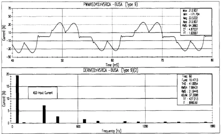
Harmonic distortion produced from the use of non-linear loads in power systems. Figure 2.2 shows the waveform and harmonic spectrum for adjustable speed drive input current. Current level of distortion can be expressed by the total harmonic distortion. For example, a lot of adjustable speed drives will display high values of total harmonic distortion input current when they are operating at very light loads, but it is not a significant concern because magnitude of harmonic currents are low, even relatively high distortion [4].
Figure 2.2: Waveform and Harmonic Spectrum for Adjustable Speed Drive Input Current [4]
2.3 Causes of Harmonic
This section describes the causes of harmonics in the industry. it includes the type of equipment that generate harmonics and equipment that contribute to the presence of harmonics.
2.3.1 Types of Equipment That Generate Harmonic
David Chapman has written in his book entitle “Harmonic causes and effects”, that the harmonic currents present in the load resulting from all the non-linear loads. There is a lot of industrial equipment used in the present that produce harmonics. The equipment can be divided into two categories single-phase load and three phase load. The examples of single-phase loads are such as the switched mode power supplies (SMPS), the electronic fluorescent lighting ballasts and the small uninterruptible power supplies (UPS). While the examples of three-phase loads are such as the variable speed drives (VSD) and the large uninterruptible power supply (UPS) units.
2.3.2 Switch Mode Power Supplies (SMPS)
Figure 2.3: Harmonic spectrum of a typical PC [3]
2.3.3 Fluorescent Lighting Ballast
A recommendation for improving energy efficiency has resulted in demand for electronic ballasts have increased in recent years. However, the difference between the efficiency of electronic ballasts and magnetic ballasts only slightly different if more efficient magnetic ballasts used.
1) Advantages using fluorescent lighting ballasts:
Light levels can be maintained throughout a long life by feedback control of current flow.
2) Disadvantages using fluorescent lighting ballasts: It will generate harmonics in the supply current.
![Figure 2.1: Basic Components and Waveform of The Effects Of Harmonic Distortion [3]](https://thumb-ap.123doks.com/thumbv2/123dok/566922.67001/20.595.103.509.456.663/figure-basic-components-waveform-effects-harmonic-distortion.webp)
![Figure 2.3: Harmonic spectrum of a typical PC [3]](https://thumb-ap.123doks.com/thumbv2/123dok/566922.67001/24.595.120.494.79.299/figure-harmonic-spectrum-typical-pc.webp)
