ELECTROMAGNETIC BAND GAP (EBG) STRUCTURE
NIK NABIHAH BINTI NIK MUSA
This report is submitted in partial fulfillment of the requirements for the award of Bachelor of Electronic Engineering (Telecommunication Electronic) With Honours
Faculty of Electronic and Computer Engineering Universiti Teknikal Malaysia Melaka
iii
“I hereby declare that this report is the result of my own work except for quotes as cited in the references.”
Signature :
Author : Nik Nabihah Binti Nik Musa
iv
“I hereby declare that I have read this report and in my opinion this report is sufficient in terms of the scope and quality for the award of Bachelor of Electronic
Engineering (Telecommunication Electronics) With Honours.”
Signature :
Supervisor‟s Name : Mr. Mohamad Zoinol Abidin Bin Abd. Aziz
v
Dedicated, in thankful appreciation for support, encouragement and understandings to my beloved mother, father, and friends for give me support to get through this
vi
ACKNOWLEDGEMENT
Alhamdulillah, praise be to Allah, the Cherisher and Sustainer of world, most Gracious, most Merciful Lord. Praise be to Allah for enabling me to complete this analysis and research for Electromagnetic Band Gap (EBG) structure project and report for my final year project.
First and foremost, I would like to express my heartily gratitude to my supervisor, Mr. Mohamad Zoinol Abidin Bin Abd. Aziz for giving the guidance and enthusiasm throughout the progress of this project.
My appreciation also goes to my family who has been so tolerant and supports me all these years. Thanks for their encouragement, love and emotional supports that they had given to me.
Nevertheless, my great appreciation dedicated to my entire friend for
vii
ABSTRACT
viii
ABSTRAK
ix
TABLE OF CONTENT
CHAP.
I
TITLE
PROJECT TITLE
THESIS STATUS DECLARATION RESEARCHER’S DECLARATION SUPERVISOR’S DECLARATION DEDICATION
ACKNOWLEDGEMENT ABSTRACT
ABSTRAK
TABLE OF CONTENTS LIST OF TABLES LIST OF FIGURES
LIST OF ABBREVIATIONS LIST OF APPENDICES
INTRODUCTION
1.1Project Background 1.2Objectives
1.3Problem Statement
PAGE
i ii iii iv v vi vii viii ix xii xiii xvi xviii
x
II
III
IV
1.4Scope Of Work
LITERATURE REVIEW
2.1Surface Wave
2.2Introduction EBG Structure
2.3Method used to analyze the features of EBG structures 2.3.1 Lumped Element Model
2.3.2 Periodic Transmission Line Method 2.3.3 Full Wave Numerical Methods 2.4 Basic Parameters of Antennas
2.5 Multiperiod EBG Design 2.6 Microstrip Patch Antenna 2.6.1 Microstrip Line Feed
MULTIPERIOD EBG STRUCTURE DESIGN
3.1Microstrip Patch Design 3.2EBG structure Design
3.2.1 Circular EBG structure design 3.2.2 Square EBG structure design 3.2.3 Triangular EBG structure design 3.3Fabrication
RESULT ANALYSIS AND DISCUSSION
4.1MIcrostrip Patch Antenna 4.2Different Shapes
4.2.1 Circular EBG structure on Same Layer with Microstrip Patch Antenna
xi
V
4.2.2 Circular EBG structure on Different Layer with Microstrip Patch Antenna
4.2.3 Square EBG structure on Same Layer with Microstrip Patch Antenna
4.2.4 Square EBG structure on Different Layer with Microstrip Patch Antenna
4.2.5 Triangular EBG structure on Same Layer with Microstrip Patch Antenna
4.2.6 Triangular EBG structure on Different Layer with Microstrip Patch Antenna
4.3Comparison for three types of EBG structure
CONCLUSIONS AND RECOMMENDATIONS
5.1 Conclusions 5.2 Recommendation
REFERENCES
APPENDIX A
43
52
53
57
58
60
62 63
64
xii
LIST OF TABLES
TABLE 4.1 4.2 4.3 4.4 4.5 4.6 4.7 4.8 4.9 4.10 4.11 4.12 4.13 4.14 4.15 TITLE
Parameters value for rectangular patch Optimization radius of circle lattices
Optimization radius of circle lattices with gap Optimization radius of circle lattices with via
Optimization radius of circle lattices with gap and via Optimization radius of circle lattices
Optimization radius of circle lattices with gap Optimization radius of circle lattices with via
Optimization radius of circle lattices with gap and via Optimization radius of square lattices
Optimization radius of square lattices with via Optimization radius of square lattices
Optimization radius of square lattices with via Optimization radius of triangular lattices Parameters of triangular lattices
xiii
LIST OF FIGURES
FIGURE 2.1 2.2 2.3 2.4 2.5 2.6 2.7 2.8 2.9 2.10 2.11 2.12 3.1 3.2 3.3 3.4 TITLE
Surface waves lead to multipath
EBG substrate for surface wave suppression: low mutual coupling microstrip array design
EBG substrate for a low profile curl antenna design Lumped LC model for EBG analysis
Periodic transmission line method for EBG analysis Full wave FDTD model for EBG analysis
1-D multiperiod EBG structure with 8 lattice cells
2-D multiperiod EBG with a longer transmission line folded back on itself
Microstrip patch antenna with 2-D multiperiod EBG structure ground plane
Structure of a microstrip patch antenna A rectangular patch
Microstrip line feed
A rectangular patch with microstrip feed line Tree diagram of circular EBG structure design EBG structure with circular lattices
EBG structure with circular lattices with gap. Gap = 0.5mm
xiv 3.5 3.6 3.7 3.8 3.9 3.10 3.11 3.12 3.13 3.14 3.15 3.16 3.17 3.18 4.1 4.2 4.3 4.4 4.5 4.6 4.7 4.8 4.9 4.10
EBG structure with circular lattices with via. (Via; r = 0.5mm, ℓ= 3.27mm )
EBG structure with circular lattices with gap + via. (Gap = 0.5mm, Via; r = 0.5mm, ℓ= 3.27mm )
Various types of circular EBG structure Tree diagram of square EBG structure design
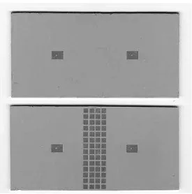
EBG structure with square lattices on second substrate
EBG structure with square lattices on second substrate. (Via; r = 0.5mm, ℓ= 3.27mm )
Various types of circular EBG structure
Tree diagram of Triangular EBG structure design EBG structure with triangular lattices
A rectangular patch antenna Circular EBG structure
Circular EBG structure with gap Square EBG structure
Triangular EBG structure
A rectangular patch with microstrip feed line Return loss for rectangular patch
Simulation and measurement radiation pattern for H-H Plane of rectangular patch
Simulation and measurement radiation pattern for E-E Plane of rectangular patch
Comparison of return loss for different type of circular EBG structure
Comparison of return loss for different type of circular EBG structure with microstrip without EBG structure
EBG structure with circular lattices
Simulated and measured return losses for circular EBG structure
Simulation and measurement radiation pattern for H-H Plane of circular EBG structure. (r = 3mm)
Simulation and measurement radiation pattern for E-E Plane
xv 4.11 4.12 4.13 4.14 4.15 4.16 4.17 4.18 4.19 4.20 4.21 4.22 4.23 4.24 4.25 4.26 4.27 4.28 4.29
of circular EBG structure. (r = 3mm)
EBG structure with circular lattices. Gap = 0.5mm Return losses for circular EBG structure with gap
Simulation and measurement radiation pattern for E-E Plane of circular EBG structure with gap (r = 3mm)
Simulation and measurement radiation pattern for H-H Plane of circular EBG structure. with gap (r = 3mm)
EBG structure with circular lattices. (Via; r = 0.5mm, ℓ= 3.27mm )
EBG structure with circular lattices on second substrate. (Gap = 0.5mm, Via; r = 0.5mm, ℓ= 3.27mm )
Comparison between microstrip without EBG and circle EBG structure with square lattices on second substrate. Return losses for square EBG structure with different size of radius
Return losses for square EBG structure
Simulation and measurement radiation pattern for E-E Plane of square lattices EBG structure
Simulation and measurement radiation pattern for H-H Plane of square lattices EBG structure
EBG structure with square lattices. (Via; r = 0.5mm, ℓ= 3.27mm )
Comparison between microstrip without EBG and square EBG structure with triangular lattices
Return loss for triangular EBG structure
Simulation and measurement radiation pattern for H-H Plane of triangular lattices EBG structure
Simulation and measurement radiation pattern for E-E Plane of triangular lattices EBG structure.
Comparison between microstrip without EBG and triangular
xvi
LIST OF ABBREVIATION
EBG - Electromagnetic Band Gap
CST - Computer Simulation Technology FR4 - Flame Retardant 4
FDTD - Finite Difference Time Domain IEEE EM GPS PEC MTL MoM FEM L C Zp Xc Z0 a1 a2 L W - - - - - - - - - - - - - - - -
Electrical and Electronics Engineers Electromagnetic
Global Positioning System Potential Equalization Clamp Multi Transmission Line Method of Moments Finite Element Method Inductance
Capacitor
Impedance for each periodic element Coupling capacitor
Initial impedance Period of lattice Period of lattice Length
xvii
c f0 ℇr ℇeff
Leff
△L h
d
ℓ r
- - - - - - - - - -
Speed of light Resonant frequency Dielectric substrate
Effective dielectric constant Effective length
Length extension Height
Thickness Length
xviii
LIST OF APPENDICES
NO TITLE PAGE
CHAPTER I
INTRODUCTION
1.1 Project Background
2
Surface wave is a mechanical wave that propagates along the interface between differing media, usually two fluids with different densities. A surface wave can also be an electromagnetic wave guided by a refractive index gradient.
1.2 Objective
The objectives of this project are to design an EBG structure that can suppress surface waves and improve the radiation performance of the antenna. The lower return loss (S11) will be obtained by suitable lattices of EBG structure. Then the performance of the antenna will be measure based on its return loss, and radiation pattern.
1.3 Problem Statement
3
1.4 Scope of Work
CHAPTER II
LITERATURE REVIEW
In this chapter, the literature reviews that had been researched are studied to understand more about Electromagnetic Band Gap (EBG) structure, and how to design it. The literature reviews that had been reviewed are closely related to the project.
2.1 Surface Wave
5
In order to suppress surface wave propagation, there were some techniques which can be use, such as special antenna designs, micromachining the substrate and employing electromagnetic band gap structure. The lack of availability of direct methods for investigating surface waves is becomes a problem in solving the suppression surface wave [6].
Figure 2.1 Surface waves lead to multipath [4]
2.2 Introduction EBG structure
In current years, there have many researches that have been done in growing interest on (EBG) structures. In solid state physics and related applied fields, a band gap, also called an energy gap or band gap, is an energy range in a solid where no electron states exist.
6
structures have their own property of reducing the phase velocity of EM modes, based on the frequencies near their band gap [8].
These structures have paying attention on a great deal of interest among researches due to their ability to influence the propagation of electromagnetic waves. The unique electromagnetic properties of EBG structures have led to a wide range of applications in antenna engineering. This section summarizes several typical EBG applications in antenna designs in the hope of stimulating discussions and new avenues of research in this area.
7
Figure 2.2 EBG substrate for surface wave suppressions: low mutual coupling microstrip array design [9].
Another favorable application of EBG is to design low profile wire antennas with good radiation efficiency, which is desired in modern wireless communication systems.
When an electric current is vertical to a Perfectly Electric Conducting (PEC) ground plane, the image current has the same direction and reinforces the radiation from the original current. Thus, this antenna has good radiation efficiency, but suffers from relative large antenna height due to the vertical placement of the current. To realize a low profile configuration, one may position a wire antenna horizontally close to the ground plane.
![Figure 2.1 Surface waves lead to multipath [4]](https://thumb-ap.123doks.com/thumbv2/123dok/637600.77410/22.595.208.433.215.358/figure-surface-waves-lead-multipath.webp)