GYROSCOPE IMPLEMENTATION ON MOBILE ROBOT ISMAIL BIN MOHD KHAIRUDDIN
UNIVERSITI TEKNIKAL MALAYSIA MELAKA FAKULTI KEJURUTERAAN ELEKTRIK
FINAL YEAR PROJECT (FYP)
BEKU 4973
GYROSCOPE IMPLEMENTATION ON MOBILE ROBOT
ISMAIL BIN MOHD KHAIRUDDIN
DEGREE OF BACHELOR IN ELECTRICAL ENGINEERING (MECHATRONICS)
“I hereby declared that I have read through this report entitle “Gyroscope Implementation On Mobile Robot” and found that it has comply the partial fulfillment for awarding the degree of
Bachelor of Electrical Engineering (Mechatronic)”
Signature : ……….
Supervisor’s Name : Encik Muhammad Fahmi Bin Miskon
GYROSCOPE IMPLEMENTATION ON MOBILE ROBOT
ISMAIL BIN MOHD KHAIRUDDIN
This Report is submitted in Partial Fulfillment of Requirements for the Degree of Bachelor in Electrical Engineering (Mechatronic)
Faculty of Electrical Engineering
UNIVERSITI TEKNIKAL MALAYSIA MELAKA
“I hereby declared that this report entitle “Gyroscope Implementation On Mobile Robot” is the result of my own work except as cited in the references.
The report has not been accepted for any degree and is not concurrently submitted in candidature of any other degree.”
Signature : ………
Name : Ismail Bin Mohd Khairuddin
ACKNOWLEDGEMENT
Alhamdulillah, finally the Final Year Project (FYP) report is complete. I’m taking this opportunity to thank to whoever generously advice and assists me while I was doing my Final Year Project (FYP) directly or indirectly.
First of all, I would like to express my deepest thanks and gratitude to my project supervisor, Encik Muhammad Fahmi Bin Miskon for undivided support morally and physically, gave assistance, guidance, tolerance, which proved to be invaluable as to the completion of my Final Year Project (FYP).
I also want to thank the panels, En Ahmad Idil b Abdul Rahman and En Aminurrashid b Noordin, for give me a good comment and developing critics during my seminar. I also would like to take this opportunity to express my appreciation to my family and friends for their patients, understanding and also for their undivided support that they had gave me throughout the completion of my project.
v
ABSTRACT
ABSTRAK
2.3.3 Adaptive Trajectory Tracking Control 9
ix
5 RESULT, DISCUSSION AND ANALYSIS 32
5.1 Signal Obverse by Oscilloscope 32
5.2 Simulation on Proteus Software 34
5.3 Real Time Simulation 36
5.4 Mobile Robot 38
5.4.1 Future Work 42
6 CONCLUSION AND RECOMMENDATION 43
6.1 Conclusion 43
6.2 Recommendation 44
REFERENCES 45
LIST OF TABLE
TABLE TITLE PAGE
3.1 Pin Description for Gyro Single Axis 17
3.2 Type of PIC18F and Characteristics 19
3.3 PIC16F87XA Characteristics 21
4.1 Input given to L298 driver for control direction of DC Brushed 29 Motor (DC Geared Motor)
5.1 The Output display in LCD during Simulation Test 35
5.2 The Result of Gyro from Ground Truth Test 37
5.3 The Voltage Measurement on DC Motor 39
5.4 The Measurement of Current on DC Motor 40
xi
LIST OF FIGURES
TABLE TITLE PAGE
2.1 Rotary (classic) Gyroscope Operation 6
2.2 Coriolis force Principle Operation 6
2.3 Optical Gyroscope Operation 7
2.4 Fire Fighting Robot 8
2.5 Schematic of Skid-Steered Mobile Robot 10
2.6 Skid-Steered 4 Wheeled Mobile Robot 10
2.7 Design Outline for Implementation of Encoder, Accelerometer 11 and Gyro
4.1 Circuit Designing on Proteus to Study the Characteristics of Gyro 26
4.3 Ground Truth Table for Real Time Simulation 28 4.4 Mobile Robot with Implementation on Gyro 30 5.1 The Waveform that Gyro Produced During in Stable Mode 33 5.2 The Output of Oscilloscope When Gyro has been detected 34
5.3 The output display on LCD 35
5.4 The Relationship between Voltage and Degree 36
5.5 The Result of Gyro during the Ground Truth Test 37 5.6 The Result between Actual Degrees with Degree from Gyro 38
5.7 Field for Mobile Robot Test 40
xiii
LIST OF ABBREVIATION
ADC : Analog Digital Converter
PIC : Programmable Intelligent Computer UPP : Universal Pulse Processor
RAM : Random Access Memory
ROM : Read Only Memory
EEPROM : Electrically Erasable Programmable Read Only Memory
I/O : Input/Output
MEMS : Micro Electro Mechanical Systems
DC : Direct Current
IFC : Interface Free Controller LCD : Liquid Crystal Display
CCP : Capture Compare Pulse Width Modulation
LIST OF APPENDICES
APPENDIX TITLE PAGE
A PIC16F877A datasheet 45
CHAPTER 1
INTRODUCTION
In this section, an introduction towards project will be briefed. This chapter consists of objective, problem statement and scope of the project.
1.1 Introduction of Project
This project is titled as “Gyroscope Implementation on Mobile Robot”. The purpose of this project is to product a mobile robot that can be turned precisely and perfectly. To accomplish this project divided on three parts: mechanical part, electrical part and software part.
In the mechanical part base for mobile robot will be constructed. It includes the finding of centre of gravity of the mobile robot. In the electrical part, the implementation of the sensor will be done, where as the connection of driven motor to the controller board is also included in this part.
2 1.2 Problem Statement
In previous Robocon competitions, the suitability of the robot(s), the efficiency of the pilot in handling the manual robot and technology used was the key of success in solving the problems and winning the competition.
The suitability of the robot depends to the paths that are used, the efficiency to do turning and also what that has been programmed with. However, there will be problems faced, when a perfect and precise turn is needed. If to be concluded from previous competition almost every robot were not able to turn precisely and perfectly. This problem will take time in the competition.
Other than that, most of robot that competes chooses to follow the line to finish the task. The problem will occur when the line is not on a flat surface (e.g. a ramp) and an obstacle is in the way. Because of the problem, it will take time. Hence, in order to solve the problem, a gyro sensor will be used.
1.3 Objective
The objectives of this project are:
1. Design and construct a mobile robot base for gyroscope implementation. Design a base to implement the gyroscope.
2. To implement gyroscope for mobile robot turning operation. Construct a programming for gyroscope that focused on turning. 3. To integrate gyro for motion on other surface.
Construct the programming for gyroscope based on the surface.
4. To implement additional usage of gyro based on Robocon 2010 theme.
1.4 Scope of Project
1. Construct a mobile robot.
2. Developing and testing the sensors (gyroscope and encoder) for mobile robot turning.
3. Programming the controller using MikroC and MPLab C Compiler software. 4. Mobile robot is tested based on the specification of Robocon field.
1.5 Layout Project Chapter 1: Introduction
This chapter will simply introduce about the project. This chapter contains introduction, objectives, scope of project and problem statement.
Chapter 2: Literature Reviews
This chapter shows about the studies and research that relevant to the project.
Chapter 3: Theory and Background
The theory of the device that has been used will be state out in this chapter
Chapter 4: Research Methodology
This part will show the canvass about the research methodology used in this project.
Chapter 5: Result, Discussion and Analysis
This part will state out the result that be obtained, discussion and analysis of the result.
Chapter 6: Conclusion and Recommendation
CHAPTER 2
LITERATURE REVIEW
To have a briefing understanding of the researches related to the project, a few literature reviews had been done. This chapter will describe the related literature reviews.
2.1 Introduction to the Gyroscope
Gyroscope or also called gyro is a sensor that measures the rotation velocity or rotation rate of an object. Theoretically, a gyroscope is any device that can measure angular velocity and primary used for navigation and also measuring the orientation based on the principle of conversation of angular momentum of [2,13].
Gyro are currently use for gaming and virtual reality input device, motion with MMI (man- machine interface), image stabilization for digital video and digital still cameras, GPS navigation system also for robotics.
2.2 Basic Operation and Types of Gyro
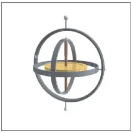
Gyro operation is differently depending on their type. Basically, gyro is has three (3) types which is rotary (classic) gyroscope, vibrating structure gyroscope and optical gyroscope [1, 2]. Traditional spinning gyroscopes work on the basis that a spinning object (disk) that is tilted perpendicularly to the direction of the spin will have a precession. The precession keeps the device oriented in a vertical direction so the angle relative to the reference surface can be measured. The spinning object is directly mounted to the series of gimbals and the gimbals offer the spinning disk to additional degree of freedom [1, 2, 13].
Vibrating structure gyroscope it is MEMS (Micro-machined Electro-Mechanical Systems) which is device/sensor that is available commercially, affordable, and very small in size [1, 2, 13]. The MEMS will convert the angular rate from gyro in different capacitive change based on the Coriolis force. Coriolis force is when an object is moving in a periodic fashion (either oscillating or rotating), rotating the object in an orthogonal plane to its periodic motion causes a translational force in the other orthogonal direction [13].
6
Figure 2.1: Rotary (classic) Gyroscope Operation