“I hereby declare that I have read through this report entitle “High Voltage and Impulse Test on Industrial Pipeline” and found that it has comply the partial fulfillment for awarding the degree of Bachelor of Electrical Engineering (Industrial Power)”
Signature : ………
Supervisor’s Name : EN. FARHAN BIN HANAFFI
i
HIGH VOLTAGE AND IMPULSE TEST ON INDUSTRIAL PIPELINE
FARAH ZUNURAIN BINTI AB. LATIF
A report submitted in partial fulfillment of the requirement for the Degree of Bachelor in Electrical Engineering (Industrial Power)
Faculty of Electrical Engineering
UNIVERSITI TEKNIKAL MALAYSIA MELAKA
ii
I declare that this report entitle “High Voltage and Impulse Test on Industrial Pipeline” is the result of my own research except as cited in the references. The report has not been accepted for any degree and is not concurrently submitted in candidature of any other degree.
Signature : ………
Name : FARAH ZUNURAIN BINTI AB LATIF
iii
Special dedicated to
My beloved parents and siblings, who have encouraged, guided and supported me
iv
ACKNOWLEDGEMENT
Alhamdulillah, I would like to express my thankfulness to the Almighty Allah S.W.T and all the praise and Selawat is upon to the Prophet Muhammad S.A.W. who has given me all the strength that I need to complete this Final Year Project report.
I would like to take this opportunity to express my deepest gratitude to my supervisor, En. Farhan Bin Hanaffi who was persistently and determinedly assisted me for give his idea and guidance along the progress of the project to make sure it successful. It would have been difficult to accomplish completely alone this Final Year Project report without enthusiastic support, insight and advice given by him.
My utmost thanks also go to my parents and family who has given me support, motivation and patience during my academic years. Without them, I might not be able to finish this project.
I have gained a lot of help and support from friends and staffs in the Faculty of Electrical Engineering. I want to take this opportunity to express special thanks to them for their advice and idea that help me to complete this Final Year Project.
Your sincere help will be remembered for life.
v
ABSTRACT
vi
ABSTRAK
vii
TABLE OF CONTENTS
CHAPTER TITLE PAGE
TITLE i
ADMISSION ii
DEDICATION iii
ACKNOWLEDGEMENT iv
ABSTRACT v
ABSTRAK vi
TABLE OF CONTENTS vii
LIST OF TABLES x
LIST OF FIGURES xi
LIST OF APPENDICES xiii
1 INTRODUCTION 1
1.1 Project Overview 1
1.2 Problem Statement 2
1.3 Objectives of the Project 3
1.4 Scopes of the Project 3
1.5 Project Outline 3
2 HIGH VOLTAGE TESTING 5
2.1 Introduction 5
viii
CHAPTER TITLE PAGE
2.7 Summary 11
3 AIR BREAKDOWN AND LIGHTNING
FLASHOVER 12
3.1 Introduction 12
3.2 Townsend’s Criterion for Breakdown 12 3.3 Streamer Theory of Breakdown 13
3.4 Lightning Flashover 15
3.5 Lightning Incidents 15
3.6 Summary 16
4 METHODOLOGY 17
4.1 Introduction 17
4.2 Development of the project 17
4.3 Test Circuit and Arrangement 20
4.3.1 AC Testing 21
4.3.2 DC Testing 23
4.3.3 Impulse Testing 24
4.4 Summary 25
5 RESULTS 26
5.1 Introduction 26
5.2 AC Testing 26
5.3 DC Testing 27
5.4 Impulse Testing 27
5.5 Summary 28
6 ANALYSIS AND DISCUSSION OF RESULT 29
6.1 Introduction 29
ix
CHAPTER TITLE PAGE
6.3 Testing under DC condition 30
6.4 Testing under Impulse condition 31 6.5 Comparison between AC, DC and Impulse testing 32 6.6 Shape of Spark Gap under High Voltage Testing 33
6.7 Summary 35
7 CONCLUSION AND RECOMMENDATION 36
7.1 Conclusion 36
7.2 Recommendation 37
REFERENCES 38
x
LIST OF TABLES
TABLE TITLE PAGE
5.1 Result of the AC Testing 26
5.2 Result of the DC Testing 27
5.3 Result of the Impulse Testing for the Test Object 28
xi
LIST OF FIGURES
FIGURE TITLE PAGE
1.1 Equipment of the experimental work 2
2.1 AC circuit 6
2.2 Measurement using capacitive divider 7
2.3 Half wave rectifier 8
2.4 Resistance potential divider 9
2.5 Wave shape for lightning impulse voltage 10
2.6 Single stage impulse generator 11
3.1 Typical current growth current in a Townsend
discharge 13
3.2 Field distortion in a gap due to space charge 14
3.3 Lightning strikes depot 16
4.1 Flow chart of the development of the project 19
4.2 Configuration of high voltage testing 21
4.3 Flow of the AC testing 22
4.4 Flow of the DC testing 23
4.5 Flow of the Impulse testing 24
6.1 Breakdown voltage under AC condition for top and
middle of the pipe 30
6.2 Breakdown voltage under DC Positive and DC
Negative 31
6.3 Breakdown voltage (KV) vs distance (cm) for Impulse
conditions 32
6.4 Breakdown voltage under AC, DC Positive and
Impulse Positive 32
6.5 Breakdown voltage under AC, DC Negative and
xii
6.6 Shape of Impulse spark 34
6.7 Shape of DC spark 34
xiii
LIST OF APPENDICES
APPENDIX TITLE PAGE
CHAPTER 1
INTRODUCTION
1.1 Project Overview
High voltage and impulse test on industrial pipeline is the project that involves in Final Year Project on. The industrial pipeline is the largest process plant and most sophisticated structures that be protected by lightning. In other hand, industrial pipeline are closely related to the lifelines of complete regions and sometimes entire countries. Special measures must be taken to insure the reliability, the quality and the efficiency of this peculiar industry. The repair costs for replacing damaged are much higher than those of installing devices.
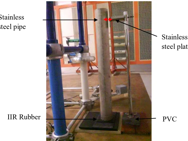
In this project will be described to analyze the breakdown voltage of the spark gap discharge that has been tested by prototype of pipeline using between stainless steel pipe and stainless steel plate. This project had been completely by tested with high voltage testing which is AC, DC and Impulse voltage.
The knowledge of the discharge developments which precede a prospective flashover in air is the basis for the identification of the withstand characteristics of air insulation. Therefore, such knowledge can also be the basis for the design of external insulation of high voltage apparatus by dimensioning its pipe termination and clearances.
2 steel pipe and plate namely 1.0cm, 1.5cm, 2.0cm, 2.5cm, 3.0cm and analyze the breakdown voltage of spark gap discharge in that gap ranging. In this experimental work, air breakdown as a media of insulation has been used.
Figure 1.1: Equipment of the experimental work
1.2 Problem Statement
Historically, lightning has been known to split trees and blow holes in the ground. Besides, it also wipes out all types of computers, electronic devices and destroys electric utility equipment causing major blackouts. Lightning can cause structural damage to building and communication systems. It also destroys electrical utility equipments causing major blackouts and damage pipe on industrial pipeline that can cause fires. From the observation, the damage of equipment caused not come from supply but it also can from lightning flashover. Direct lightning strikes are really a threat for industrial pipeline. Besides, lightning flashover does not have exactly safety statement on industrial pipeline. Lightning will be strike and flow to the ground and also to the equipment that has low earthing resistance. It will affect the behavior of pipeline and other equipment.
Stainless steel plate Stainless
steel pipe
3 1.3 Objectives of the Project
There are four objectives for fulfill in this project:
i. To study about lightning flashover effect in pipeline industrial. The industrial pipeline is the process plants belong to the largest and most sophisticated structures to be protected against lightning.
ii. To study about air breakdown which is media of insulation had been used. iii. To investigate breakdown voltage of the spark gap discharge.
iv. To design a prototype of pipeline where used a stainless steel pipe and stainless steel plate for the experiment.
1.4 Scopes of the Project
To achieve the objective of the project, this is scopes of the project as a guideline:
i. Study about high voltage and impulse experiment for the flashover phenomena based on the theoretical which has related to the air breakdown.
ii. Analyze the air breakdown which is that media of insulation to be used.
iii. Using the stainless steel pipe and stainless steel plate that be used in chemical industrial because protected it from corrosion and stress.
iv. Analyze safety gap discharge with gap ranging 1.0 cm, 1.5 cm, 2.0 cm, 2.5 cm and 3.0 cm.
v. Use AC, DC and Impulse voltage for the testing.
1.5 Project Outline
4 Impulse Test in Industrial Pipeline. Included is objectives for fulfill in this project and scopes of the project as a guideline to achieve the objectives of the project.
Chapter 2 reviews about high voltage testing which is generation and measurement of AC, DC and Impulse voltage. From this chapter shown how to generate and measure high voltage testing. Chapter 3 discusses about conduction and breakdown in air. The principal media of insulation has been used in this project is air. In this chapter also covers about flashover on industrial pipeline. The case study about lightning flashover incident that occur at Johor Port, Pasir Gudang also includes in this chapter.
Chapter 4 covers methodology for development of the project and explains all five phases that contain in flow of the project in order to all works movement according to the plan. Test circuit and arrangement also contains in this chapter which is explaining the flow of the procedure the experimental work subjected to AC, DC and Impulse voltage testing.
Chapter 5 presents the result of the breakdown voltage that obtained from the experimental work. The result had been fill in the table which is can show the result more clearly. There are had eight result of the breakdown voltage in gap ranging from 1.0cm, to 3.0 cm which is for AC testing at the top and middle of the pipe. For DC testing had been testing at two conditions which are DC positive and DC negative and also for Impulse testing in two conditions positive and negative. Before that, for the impulse testing, the breakdown voltage at the sphere gap had measured first in two conditions positive and negative.
Chapter 6 discusses about the analysis and discussion of the result. The result will be showed with graph to analysis or compared with the previous journal. At the Chapter 7 covers about conclusion of this Final Year Project report that the objectives of this project had been achieved and the recommendation can be made to upgrade for future works.
CHAPTER 2
HIGH VOLTAGE TESTING
2.1 Introduction
High voltage testing is according to ANSI/IEEE Standard 100-1984 which is test that consists of the application the voltage higher than the rated voltage for the purpose to determine the adequacy against breakdown of insulating materials and spacings under normal conditions [1].
In other words, high voltage testing is any test done where the electric field gradient (stress) is sufficient to test and evaluate the properties of the insulation system in the performance of the device [1].
In the fields of electrical engineering and applied physics, high voltages of all types, namely AC, DC and Impulse are required for several applications. The generation of high voltages in a high voltage laboratory is required for the purpose of testing various types of power system equipment.
2.2 Generation of High AC Voltage
6 of the value of the voltage. This demand can normally only be fulfilled by measurement of the voltage on the high voltage side.
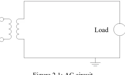
Load
Figure 2.1: AC circuit
When test voltage requirements are less than 300kV, a single transformer can be used for test purposes. The impedance of the transformer should be generally less than 5% and must be capable of giving the short circuit current for one minute or more depending on the design [2].
The most common method of high AC voltage generation is using step-up test transformers. The test transformers mainly used to provide high AC voltages for various AC tests such as withstand flashover as well as partial discharge tests.
2.3 Measurement of AC High Voltage
Measurement with capacitive dividers is methods available for measuring high AC voltages. The incorporation of an oscilloscope in some of the measurement techniques makes it possible to view the waveshapes.
7
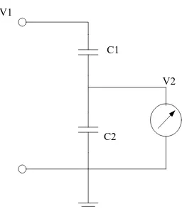
(2.1)
Where Cm is the capacitance of the meter and the connecting cable and the leads and V2 is the meter reading.
V1
V2 C1
C2
Figure 2.2: Measurement using capacitive divider
2.4 Generation of High DC Voltage
Generation of high DC voltages is required in research work in the areas of pure and applied physics, insulation tests [2]. Because of the diversity in the application of DC high voltages, ranging from basic physics experiments to industrial applications, the requirements on the output voltage will vary accordingly. A detailed understanding of various types of generating circuits based on the AC to DC conversion is emphasized. The rectification of alternating currents is the most efficient means of obtaining high voltage DC supplies.
The DC test voltage is defined as the arithmetic mean value between the highest and lowest level within a period:
(2.2)
8
(2.3)
The ripple is influenced by the load current, frequency and the smoothing capacitance.
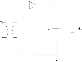
For the DC configuration is realized with a half-wave rectifier circuit. Figure 2.3 shows half-wave rectifier. In the half wave rectifier, the capacitor is charged to Vmax, the minimum AC voltage of the secondary of the high voltage transformer in the conducting half cycle. In the other half cycle, the capacitor is discharged into the load. The rectifier valve must have a peak inverse rating of at least 2Vmax [2].
C
+
-RL
Figure 2.3: Half wave rectifier
For high voltage test circuits, a sudden voltage breakdown at the load (RL nearing to 0) must always be taken into account. The rectifiers should be able to carry either the excessive currents, which can be limited by fast, electronically controlled switching devices at the transformer input or can be protected by an additional resistance inserted in the high voltage circuit.
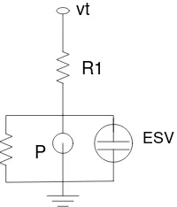
2.5 Measurement of DC High Voltage
9 Figure 2.4. The influence of temperature and voltage on the elements is eliminated in the voltage divider arrangement. The high voltage magnitude is given by expression:
(2.4)
Where V2 is the DC voltage across the low voltage arm R2.
vt
R1
ESV
P
Figure 2.4: Resistance potential divider
2.6 Generation of High Impulse Voltage
Impulse voltages are required in high voltage tests to simulate the stresses due to external and internal overvoltages and also for fundamental investigations of the breakdown mechanism. It is usually generated by discharging high-voltage capacitors through switching onto a network of resistors and capacitors whereby multiplier circuits are often used [3].
10 For overvoltages following lightning strokes, the time required to reach the peak value is in the order of 1µs are named atmospheric or external overvoltages. Voltage generated in a laboratory to simulate these is called lightning impulse voltage (LI) [3]. The peak value of impulse voltages can be determined with the aid of measuring gaps or better be measured by electronic circuits combined with voltage dividers. The most important measuring device for impulse voltage is the cathode ray oscilloscope which allows the complete time characteristics of the voltage to be determined by means of voltage dividers.
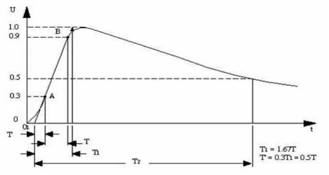
For impulse testing, special wave forms must be generated to approximate the expected impulse (surge) voltages that are likely to stress high voltage equipment. Figure 2.5 shows the wave shapes for lightning impulse voltage which is determined by certain time parameters for the front and tail. Since the true shape of the front of lightning impulse voltages is often difficult to measure, the straight line O1S1 through the point A and B is introduced as an auxiliary construction on the front, to characterize the latter. Then, the time Ts to front, as well as the time Tr to haif value being the time from O1 to the point C are also determined [IEC Publ. 60-1 (1989)]. Lightning impulse voltages of shape 1.2/50 are generally used which means an impulse voltage with Ts = 1.2µs ± 30% and Tr = 50µs ± 20%.
Figure 2.5: Wave shape for lightning impulse voltage