ISSN: 1693-6930
accredited by DGHE (DIKTI), Decree No: 51/Dikti/Kep/2010 279
Dynamic Model and Robust Control of Flexible Link
Robot Manipulator
Mohammad Khairudin*1, Zaharuddin Mohamed 2, Abdul Rashid Husain2 1
Department of Electrical Engineering, Universitas Negeri Yogyakarta Jl. Colombo 55281 Karangmalang-Yogyakarta, Indonesia, Telp/Fax +62274-548161
2
Faculty of Electrical Engineering, Universiti Teknologi Malaysia, P08 Building, FKE-UTM, Skudai, 81310 Johor, Malaysia, Telp. +607-5535292
e-mail: [email protected]*1, [email protected], [email protected]
Abstrak
Problematika dalam robot lengan lentur adalah adanya parameter yang tidak terbatas dan tidak linear. Paper ini menyajikan desain kendali kokoh menggunakan regulator kuadratik linear (LQR) pada robot lengan lentur. Evaluasi ketangguhan sistem meliputi kemampuan pelacakan input pada respon posisi hub, perpindahan ujung lengan, residual ujung lengan dan kecepatan hub. Sebagai metode kendali, LQR dikembangkan untuk mengatasi masalah kekokohan dan kemampuan pelacakan input pada respon posisi hub. Verifikasi hasil kendali LQR dilakukan melalui perbandingan hasil menggunakan kendali PID, untuk membuktikan dan memverifikasi keunggulan kendali robust yang diusulkan sebagai alternatif pada kendali robot lengan lentur. Hasil kendali kokoh menunjukkan settling time yang lebih cepat, overshoot yang lebih kecil, serta performa yang lebih baik dibandingkan dengan menggunakan pengendali PID.
Kata kunci: LQR, kendali kokoh, model dinamis, robot lengan fleksibel link
Abstract
The problems of a flexible link manipulator are uncertainties and parametric nonlinearities. This paper presents design and development of a robust control based on linear quadratic regulator (LQR) for a flexible link manipulator. System performances were evaluated in terms of input tracking capability of hub angular position response, end-point displacement, end-point residual and hub velocity. For the controller of the system, LQR was developed to solve flexible link robustness and input tracking capability of hub angular position. The results achieved by the proposed controller are compared with conventional PID, to substantiate and verify the advantages of the proposed scheme and its promising potential in control of a flexible link manipulator. The robust control presented faster settling time and smaller overshoot responses and tracking performances of the proposed controller compared with PID controllers.
Keywords: dynamic model, flexible link manipulator, LQR, robust control
1. Introduction
Flexible manipulators have several advantages over rigid robots: they require less material, are lighter in weight, consume less power, require smaller actuators, are more maneuverable and transportable, have less overall cost and higher payload to robot weight ratio [1]. These types of robots are used in a wide spectrum of applications starting from simple pick and place operations of an industrial robot to micro-surgery, maintenance of nuclear plants and space robotics [2].
Due to the flexible nature of the system, the dynamics are highly non-linear and complex. Problems arise due to lack of sensing, vibration due to system flexibility, imprecise positional accuracy and the difficulty in obtaining accurate model for the system [3]. Moreover, the complexity of this problem increases when the flexible manipulator carries a payload. Practically, a robot is required to perform a single or sequential task such as to pick up a payload, move to a specified location or along a pre-planned trajectory and place the payload. Previous investigations have shown that the dynamic behaviour of the manipulator is significantly affected by payload variations [4].
and dynamic characteristics of the system and construct a suitable mathematical framework. The numerical analysis methods that are utilized include finite difference and finite element methods. Both approaches have been used in obtaining the dynamic characterization of single-link flexible manipulator systems incorporating damping, hub inertia and payload [5]. Performance investigations have shown that the finite element method can be used to obtain a good representation of the system [3]. De Luca and Siciliano [6] have utilised the AMM to derive a dynamic model of multilink flexible robot arms limiting to the case of planar manipulators with no torsional effects. The models also derived using combined Eular Lagrange and AMM for various payload profiles [7].
There is great interest in the development of control strategies for use with flexible link manipulators at present. The difficulties of flexible manipulator control are exacerbated by the fact that control inputs as well as external disturbances induce flexural vibrations in the manipulator structures. However, the complexity of the modelling process increases dramatically as compared to the case of a single-link flexible manipulator. Yang and Sadler [8] and Dogan and Istefanopulos [9] have developed the finite element models to describe the deflection of a planar two-link flexible robot manipulator. On the other ways, Han et al. [10] using model reference adaptive control with PD (MRAC-PD) gain to keep certain relationship which is defined as synchronization motion of the two-link mechanism. In order to guarantee a desired tracking performance, a time-variable and time-coefficient of the reference trajectory is used model predictive control [11].
This paper presents the dynamic modeling and control of a flexible link robot manipulator. System responses namely hub angular position response, end-point displacement, end-point residual and hub velocity are evaluated. The work presented forms the basis of design of a suitable control method for flexible link manipulator systems using a LQR robust control. This controller is used to achieve of high-precision input tracking capability. The LQR robust controller design maximizes the control performance guaranteeing a good precision when regulating the tip position of the flexible link manipulator in the presence of parameter uncertainties [12] and [13].
2. Research Method
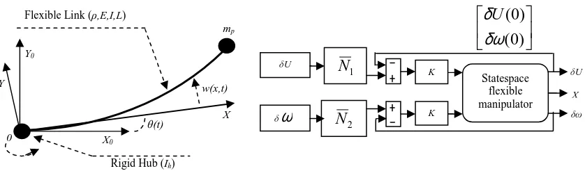
Figure 1 shows a structure of flexible link manipulator system considered in these investigations. The link is cascaded in a serial fashion and is actuated by rotor and hub with individual motor. The link has length l with uniform mass density per unit length ρ. The link is clamped at the rotor of the motor. E and I represent Young modulus and area moment of inertia of both links respectively. X0Y0 is the inertial co-ordinate frame, XY is the rigid body coordinate frame associated with the link.
θ
is the angular positions andw
(
x
,
t
)
is the transverse component of the displacement vector.m
p is an inertial payload mass with inertiaI
p at theend-point of link.
The physical parameters of the flexible link manipulator system mh is the mass considered at the motor which is located in clamped with motor, Ih is the inertia of the motor and hub. The input torque, τ (t) is applied at each motor and G is the gear ratio for the motor. Link and motor are considered to have the same dimensions.
2.1. The Dynamic Modeling of a Flexible Link Manipulator
The total displacement y(x,t) of a point along the manipulator at a distance x from the hub can be described as a function of both the rigid body motion θ(t) and elastic deflection
) , ( tx
w measured from the line OX as
) , ( ) ( ) ,
(xt x t w xt
y = θ + (1)
Using the standard FE method to solve dynamic problems, leads to the well-known equation
( )
xt N( ) ( )
x Q twhere
N
a( )
x
andQ
a( )
t
represent the shape function and nodal displacement respectively.The manipulator is approximated by partitioning it into
n
elements. As a consequence of using the Bernoulli-Euler beam theory, the FE method requires each node to possess two degrees of freedom, a transverse deflection and rotation. These necessitate the use of Hermite cubic basis functions as the element shape function. Hence, for an elemental lengthl
, the shape function can be obtained as[
( ) ( ) ( ) ( )]
)
(x 1 x 2 x 3 x 4 x
Na = φ φ φ φ (3)
where 3 3 2 2 1 2 3 1 ) ( l x l x
x = − +
φ ; 2 3 2 2 2 ) ( l x l x x
x = − +
φ ; 3 3 2 2 3 2 3 ) ( l x l x
x = −
φ ;
2 3 2
4( )
l x
l x
x =− +
φ .
For element
n
the nodal displacement vector is given as[
() () () ( )]
)
(t w 1 t 1 t w t t
Qa = n− θn− n θn (4)
where wn−1(t) and wn(t) are the elastic deflections of the element and θn−1(t) and θn(t) are the corresponding rotations. Substituting for
w ,
( )
x
t
from equation (2) into equation (1) and simplifying yields( )
x,t N(x)Q (t)y = b (5)
where
[
( )]
)
(x x N x
N = a and Qb(t)=
[
θ(t) Qa(t)]
TThe new shape function N(x) and nodal displacement vector Qb(t) in equation (3) incorporate local and global variables. Among these, the angle θ(t) and the distance x are
global variables while Na(x) and Qa(t) are local variables. Defining
∑
− = − = 1 1 n i i l xk as a local
variable of the nth element, where li is the length of the ith element, the kinetic energy of an element
n
can be expressed as taken from (Martins [3]).b T l T b T l l n
K dk SY Ydk Q S N N dk Q
t t k y S
E & & & &
= = ∂ ∂ =
∫
∫
∫
( ) 2 1 2 1 ) , ( 2 1 0 0 0 2 ρ ρ ρ (6)Figure 1. Structure of a flexible link manipulator. Figure 2. Structure of a LQR.
Rigid Hub (Ih) Flexible Link (ρ,E,I,L)
0
w(x,t)
X0
θ(t) X mp Y Y0
)
0
(
)
0
(
δω
δ
U
Statespace flexible manipulator K K δUδ
ω
N
21
N
δω δU
and the potential energy of the element can be obtained as b T l T b b T b l l n
P dk EI Q Q dk Q EI dk Q
k t k y EI E Φ Φ = Φ Φ = ∂ ∂ =
∫
∫
∫
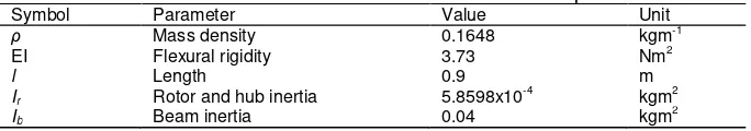
( ) 2 1 ) ( ) ( 2 1 ) , ( 2 1 0 0 2 2 2 0 (7) where 2 2 dk N d =Φ . Defining Mn and Kn as
dk N N S M T l
n ( )
0
∫
= ρ
= element mass matrix (8)
dk EI
K T
l
n ( )
0
Φ Φ =
∫
= element stiffness matrix (9)
the desired dynamic equations of motion of the system can accordingly be obtained as
) ( ) ( ) ( )
(t DQt KQt F t Q
M&& + & + = (10)
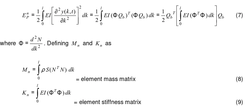
2.2. LQR Controller
Linear quadratic regulator (LQR) is a technique in modern control in which uses state-space approach to analyze such a system. MIMO design approach is the optimal control method LQR. The idea is to transfer the designer’s iteration on pole locations as used in full state feedback to iterations on the elements in a cost function, J. This technique determines the feedback gain matrix that minimizes J in order to achieve some compromise between the use of control effort, the magnitude, and the speed of response that will guarantee a stable system. Using state-space methods it is relatively simple to work with a multi-output system. The system can be stabilized using full state feedback. The schematic of LQR of control system is shown in Figure 2.
For the given system, X& =AX +BU , determine the matrix K of the LQR vector
) ( )
(t KX t
U =− . Therefore, in order to minimize the performance index, equation (11) should be satisfied.
∫
∞ + + = 0 ) 2(X QX U RU X NU dt
J T T T (11)
where Q and R are the positive-definite Hermitian or real symmetric matrix. In addition to the state-feedback gain K, lqr returns the solution S of the associated Riccati equation as shown in (12).
0 ) (
)
( + 1 + + =
−
+SA SB N R− B S N Q
S
AT T T (12)
Matrix K can be derived from S by equation (11)
) (
1 T T
N S B R
K= − + (13)
To realize the controller design, the hovercraft system must satisfy the following conditions: a. The pair (A,B) is stabilize
b. R>0 and Q-NR-1NT≥0
In designing LQR controller, LQR function in matlab m-file can be used to determine the value of the vector K which determines the feedback control law. This is done by choosing two parameter values, input (R)=1 and Q=C'xC where C is from state equation in (8). The controller can be tuned by changing the nonzero x and y elements in Q matrix which is done in m-file code.
3. Results and Discussion
The dynamic model of flexible link manipulator has been presented. The physical parameters of the manipulator are given near similar as taken from [6] with attached Payload inertia max Ip =0.0025 kgm2 and payload mass max Mp =0.5 kg. In this study, the damping ratios were assumed as 0.0086 and 0.01 for vibration modes 1 and 2 respectively. Table 1 summarises the parameters of flexible link manipulator. Otherwise, close loop system using a step input position in radian allowing the manipulator. The output responses of the manipulator are taken from both angle rotation, modal displacement, end point residual and hub velocity.
In this section, simulation results of the dynamic and LQR control of the flexible link manipulator system are presented in the time domains. System responses are monitored for duration of 5 s, and the results are recorded with a sampling time of 10 ms. The input system uses a step input of 1 rad. Three system responses namely the angular positions, modal displacement and hub velocity at link are obtained and evaluated. In this study, the LQR design is performed in two steps, firstly LQR1 with gain Q=C*C’, which produces the result that should be improved. The next step, is improved to LQR2 with gain Q=diag(size(C)).
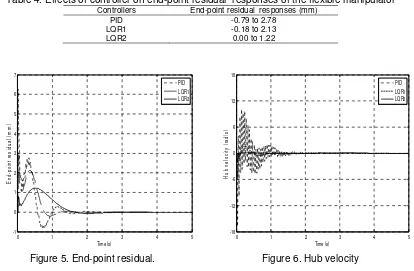
Table 1. Parameters of the one-link flexible manipulator
Symbol Parameter Value Unit
ρ Mass density 0.1648 kgm-1
EI Flexural rigidity 3.73 Nm2
l Length 0.9 m
Ir Rotor and hub inertia 5.8598x10
-4
kgm2
Ib Beam inertia 0.04 kgm2
Figure 3 shows the hub angular positions response of flexible link manipulator with the LQR2 robust control and PID controllers. It has been demonstrated that both techniques are able to meet the desired angular positions of 1.0 rad. Both using LQR2 robust control and PID control results show similar results, where steady state angular position levels of 1 rad are achieved respectively. The transient response specifications of the hub angular position for both results are summarised in Table 2. It is also noted with the LQR2 control, the system exhibits faster settling times and lower overshoots for link as compared to PID control. For the overshoot, LQR2 robust control provides more than two-fold improvements for link.
0 1 2 3 4 5
0 0.2 0.4 0.6 0.8 1 1.2 1.4
Time (s)
H
u
b
a
n
g
le
(
ra
d
)
PID LQR1 LQR2
0 1 2 3 4 5
-6 -4 -2 0 2 4 6
Time (s)
E
n
d
-p
o
in
t
d
is
p
la
c
e
m
e
n
t
(m
m
)
PID LQR1 LQR2
Figure 4 shows results of the end-point displacement responses of flexible link. It is noted that the magnitudes of vibration of the end-point displacement responses decrease using LQR2 compared with PID control. With LQR robust control, the maximum magnitudes of the responses were 2.23 mm and 0.68 mm for LQR1 and LQR2 respectively. On the other hand with PID control, the maximum magnitudes were 4.77 mm. In addition with the robust controller, the displacements converge to zero faster than the response with the ZN-PID control. Table 3 summarises the modal displacement responses.
Table 3. Effects of controller on maximum magnitudes of the displacement responses of the flexible manipulator
Controllers Maximum magnitudes of the displacement (mm)
PID 4.77
LQR1 2.23
LQR2 0.68
Figure 5 shows the end-point residual responses of the system obtained with LQR robust control and PID control exercises. With LQR1 and LQR2 robust control show that the vibration occurs at -0.18 mm to 2.13 mm and 0.00 mm to 1.22 mm respectively. Otherwise, the end-point residual response with PID was obtained at -0.79 mm to 2.78 mm.It is also noted with the LQR2 control, the system exhibits lower amplitudes of vibration for link as compared with PID control. Table 4 summarises end-point residual responses for flexible link using LQR robust control and PID control.
Table 4. Effects of controller on end-point residual responses of the flexible manipulator Controllers End-point residual responses (mm)
PID -0.79 to 2.78
LQR1 -0.18 to 2.13
LQR2 0.00 to 1.22
0 1 2 3 4 5
-1 0 1 2 3 4 5 6 7
Time (s)
E
n
d
-p
o
in
t
re
s
id
u
a
l
(m
m
)
PID LQR1 LQR2
0 1 2 3 4 5
-18 -12 -6 0 6 12 18
Time (s)
H
u
b
v
e
lo
c
it
y
(
ra
d
/s
)
PID LQR1 LQR2
Figure 5. End-point residual. Figure 6. Hub velocity Table 2. Relation between payloads and specification of
hub angular position response
Controllers Settling time (s) Overshoot (%)
PID 1.42 15.14
LQR1 2.21 5.20
Figure 6 shows the hub velocity responses obtained with LQR robust control and PID control exercises. With LQR1 and LQR2 robust control show that the vibration occurs at -5.53 rad/s to 1.63 rad/s and -2.10 rad/s to 0.29 rad/s respectively. Otherwise, the hub velocity response with PID was obtained at -16.80 rad/s to 10.13 rad/s. It is also noted with the LQR2 control, the system exhibits faster moving to zero velocity for link as compared with PID control. Table 5 summarises hub velocity responses for flexible link using LQR robust control and PID control.
Table 5: Effects of controller on hub velocity responses of the flexible manipulator Controllers Hub velocity responses (rad/s)
PID -16.80 to 10.13
LQR1 -5.53 to 1.63
LQR2 -2.10 to 0.29
4. Conclussion
The development of dynamic model and LQR robust control of flexible link manipulator has been presented. Implementations and results with simulation exercises of LQR controller for position control a single-link flexible manipulator have been presented. Initially, a PID controller has been developed for control of a flexible link manipulator. A LQR robust controller has been implemented for input tracking control capability of hub angular position response, end-point displacement, end-point residual and hub velocity of the flexible link manipulator. Performance of the control schemes have been evaluated in term of the input tracking capability, end-point displacement, end-point residual and hub velocity and robustness of the flexible link manipulator as compared with PID control. Simulation results have shown that both controllers are able to meet the desired hub angular positions for link under all conditions. However, the PID controller need to be re-tuned to find new PID gains for each condition whereas the new gains obtained with the LQR approach can be used for all cases. This is an advantage of the proposed robust LQR control. Moreover, the LQR robust controller has been shown to provide better performance as compared to the PID controller. LQR robust controller gives faster settling times and less overshoot for the hub angular position response, and lower displacement for links. These results will be verified on the hardware experimental work for future work.
References
[1] Tokhi M O, Mohamed Z, and Shaheed M H. Dynamic Characterisation of a Flexible Manipulator
System. Robotica. 2001; 19(5): 571-580.
[2] Dwivedy S K, and Eberhard P. Dynamic Analysis of Flexible Manipulators, a Literature Review.
Mechanism and Machine Theory. 2006; 41: 749-777.
[3] Martins J M, Mohamed Z, Tokhi M O, Sa da Costa J, and Botto M A. Approaches for Dynamic
Modeling of Flexible Manipulator Systems. IEE Proc-Control Theory and Application. 2003; 150(4):
401-411.
[4] Mohamed Z, and Tokhi M O. Command Shaping Techniques for Vibration Control of a Flexible
Manipulator System. Mechatronics. 2004; 14(1): 69-90.
[5] Aoustin Y, Chevallereau C, Glumineau A and Moog C H. Experimental Results for the End-Effector
Control of a Single Flexible Robotic Arm. IEEE Transactions on Control Systems Technology. 1994;
2: 371-381.
[6] De Luca A, and Siciliano B. Closed-Form Dynamic Model of Planar Multi-Link Lightweight Robots.
IEEE Transactions on Systems, Man, and Cybernetics. 1991; 21(4): 826-839.
[7]M. Khairudin, Z. Mohamed, A.R. Husein, M.A. Ahmad. Dynamic Modelling and Characterization of A
Two-Link Flexible Manipulator. Journal of Low Frequency Noise and Vibration Active Control. 2010;
29(3): 207-219.
[8] Yang Z, and Sadler J P. Large-Displacement Finite Element Analysis of Flexible Linkage. ASME
Journal of Mechanical Design. 1990; 112: 175-182.
[9] Dogan M, and Istefanopulos Y.Optimal Nonlinear Controller Design for Flexible Robot Manipulators
with Adaptive Internal Model. IET Control Theory and Applications. 2007; 1(3): 770-778.
[10] Han Q, Yang X, Zhao X, and Wen B. Controlled Synchronous Motions of a Two-Link Mechanism
Based on Improved MRAC-PD controller.Int. Journal ICIC, 2010; 6(11): 4911-4922.
[11] Henmi T, Ohta T, Deng M, and Inoue A. Tracking Control of a Two-Link Planar Manipulator Using
[12]Araghi L F, Habibnejad M K, Nikoobin A, and Setoudeh F. Neural Network Controller Based on PID
Controller for Two-links Robotic Manipulator Control. The World Congress on Engineering and
Computer Science WCECS. San Francisco. USA. 2008: 1018-1023.
[13]Tian L, and Collins C. A Dynamic Recurrent Neural Network Based Controller for a Rigid-Flexible