i
FPGA – BASED LINE FOLLOWING ROBOT
NURUL IZZATY SYAFINAZ BINTI SAIFUL AZRAN
A report submitted in partial fulfillment of the requirements for the degree
of Bachelor Degree in Electronic Engineering ( Computer Engineering)
Faculty of Electronics & Computer Engineering
UNIVERSITI TEKNIKAL MALAYSIA MELAKA
ii
UNIVERSTI TEKNIKAL MALAYSIA MELAKA
FAKULTI KEJURUTERAAN ELEKTRONIK DAN KEJURUTERAAN KOMPUTER
BORANG PENGESAHAN STATUS LAPORAN PROJEK SARJANA MUDA II
Tajuk Projek : …FPGA-BASED LINE FOLLOWING ROBOT
Sesi Pengajian : 1 5 / 1 6
Saya NURUL IZZATY SYAFINAZ BINTI SAIFUL AZRAN mengaku membenarkan Laporan Projek Sarjana Muda ini disimpan di Perpustakaan dengan syarat-syarat kegunaan seperti berikut:
1. Laporan adalah hakmilik Universiti Teknikal Malaysia Melaka.
2. Perpustakaan dibenarkan membuat salinan untuk tujuan pengajian sahaja.
3. Perpustakaan dibenarkan membuat salinan laporan ini sebagai bahan pertukaran antara institusi pengajian tinggi.
4. Sila tandakan ( √ ) :
SULIT* *(Mengandungi maklumat yang berdarjah keselamatan atau kepentingan Malaysia seperti yang termaktub di dalam AKTA RAHSIA RASMI 1972)
TERHAD** **(Mengandungi maklumat terhad yang telah ditentukan oleh organisasi/badan di mana penyelidikan dijalankan)
TIDAK TERHAD
Disahkan oleh:
__ ________________________ ___________________________________ (TANDATANGAN PENULIS) (COP DAN TANDATANGAN PENYELIA)
iii
“I hereby declare that the work in this project is my own except for summaries and quotations which have been duly acknowledge.”
Signature : ...
Author : Nurul Izzaty Syafinaz Binti Saiful Azran
iv
“I acknowledge that I have read this report and in my opinion this report is sufficient in term of scope and quality for the award of Bachelor of Electronic Engineering
(Computer Engineering) with Honours.”
Signature : ...
Supervisor’s Name : En. Sani Irwan B. Md Salim
v
This is dedicated to all my beloved people in my life especially my family, friends, and
vi
ACKNOWLEDGEMENT
I am grateful to God for the mercy and blessing given to me to fulfil my Final Year Project, FPGA-Based Line Following Robot.
In preparing this project, I would like to express my gratitude to these people who have helped me along the way. This project could not have been fulfilled without help of as my supervisor, Mr. Sani Irwan Bin Md Salim. Thank you very much for patiently guided me through the completing this final year project.
My sincere appreciation also goes to my family especially my parents who have morally and financially supported me from the beginning of my studies. Thank you for always reminding me to never procrastinate with my work and to always believe in myself.
Thanks to all my friends who have provided assistance in numerous ways; the words of wisdom, the tips and advices given definitely have helped me fulfil this final year project. Not to forget, thanks to all people who have helped me to fulfil this final year project.
vii
ABSTRACT
viii
ABSTRAK
ix
TABLE OF CONTENTS
CHAPTER TITLE PAGE
PROJECT TITLE i
REPORT STATUS VERIFICATION FORM ii
STUDENT’S DECLARATION iii
SUPERVISOR’S DECLARATION iv
DEDICATION v
x
2.4 A Line Follower Robot from Design to 6
Implementation: Technical Issues and Problem
xi
IV RESULT AND DISCUSSION 29
4.1 Hardware 29
4.1.1 Input (Sensor) 29
4.1.2 FPGA 30
4.1.3 Output (Motor) 33
4.2 Software 36
4.2.1 Simulation 36
4.3 Discussion 40
V CONCLUSION AND RECOMMENDATION 41
5.1 Conclusion 41
5.2 Future Recommendation 42
xii
LIST OF TABLES
NO. TITLE PAGE
xiii
LIST OF FIGURES
NO. OF FIGURE TITLE PAGE
2.1 Line follower block diagram 7
2.2 Sensors location method 8
2.7 Sensor Infra-Red Emitter & Receiver 13
2.8 The SoC solution for the robot line-following project 14
2.9 The Experimental Procedure – Sensor Motion over 14
a Grayscale
2.10 IP core outputs for sensor motion over a 15
quantized grayscale surface (10 bit resolution setting)
2.11 IP core outputs for sensor motion over a 15
quantized grayscale surface (7 bit resolution setting)
2.12 Block diagram 17
2.13 Simulation of white line follower and black line 17
xiv
3.8 Spartan-6 Papilio Pro board 26 3.9 Block Diagram of Comparator LM339 27
xv
ABBREVIATIONS
FPGA – Field Programmable Gate Array
I/O – Input/Output
IR – Infrared
HDL – Hardware Description Language
RISC – Reduce Instruction Set Computer
1
CHAPTER I
INTRODUCTION
1.1Project overview
2
make it able to function according to the needs of the user. It is most commonly used in describing digital circuits at the register-transfer level (RTL).
1.2Objectives
The objective of this project is to design and develop a line follower robot controller using Field Programmable Gate Array (FPGA).
1.3Problem Statement
Usually, a line following robot use a microcontroller as the controller for the system. However, there are some limitation when using a microcontroller as the input output pins are preconfigured according to the packaging. If there is any changes in the design or in need of adding new features, the microcontroller needs to be replaced as a whole. To overcome this limitation, FPGA is used instead of microcontroller as the input and output pins are reconfigurable and will accommodate all the required pins for the system.
1.4Scope
The scope of this project is to implement the FPGA-based controller on the line following robot. Verilog HDL will be used to describe the hardware architecture. Spartan-6 FPGA board is utilized as the platform for the hardware programming. In this project, the line following robot will accommodate four infrared sensors as the input and two servo motors as the output to determine the direction of the robot.
1.5Thesis Organization
This thesis consists of five chapters: Introduction, Literature Review, Methodology, Result and Analysis, and Conclusions and Recommendations.
3
to FPGA and existing project related to this project will be discussed. The concept and the fundamental basis of FPGA will also be included in this chapter.
In Chapter 3, the methodology for this project is discussed. It will be focused on the hardware development and the experimental setup. The experimental results and analysis of the prototype will be discussed in Chapter 4.
4
CHAPTER II
LITERATURE REVIEW
This chapter summarizes the literature review on theoretical concepts applied in this project. It contains the information that the project required in order to develop and complete the entire project.
2.1 Introduction to FPGA
Field Programmable Gate Arrays (FPGA) are reconfigurable hardware devices that can be reprogrammed to implement different combinational and sequential logic created with the aim of prototyping digital circuits, as they offer flexibility and speed. They are alternative to implementation of digital logic in systems. In recent years, the advance in technology have permitted to construct FPGAs with considerable large amounts of processing power and memory storage, and as so they have been applied in several domains (telecommunications, robotics, pattern recognition tasks, infrastructure monitoring, etc.). It designed the flexibility to create a wide array of logic circuits at a low cost because it is not necessary to manufacture a new custom made integrated circuit each time. It can be programmed to implement any digital design from a very simple ‘AND’ circuit to a very complex multiplexer circuit. The first FPGA contains 64 CLBs and 58 inputs and outputs. Today’s FPGA can contain about 330,000 logic blocks and around 1100 inputs and outputs.
5
2.1.1 FPGA Architecture
Field Programmable Gate Arrays (FPGAs) are pre-fabricated silicon devices that can be electrically programmed in the field to become almost any kind of digital circuit or system. The general FPGA architecture consists of three types of modules. They are I/O blocks or Pads, Switch Matrix/ Interconnection Wires and Configurable logic blocks (CLB). The basic FPGA architecture has two-dimensional arrays of logic blocks with a means for a user to arrange the interconnection between the logic blocks. The functions of an FPGA architecture module are discussed below:
• Configurable Logic Block (CLB) includes digital logic, inputs and outputs. To implement the combinational and sequential logic
• Interconnects is the wires to connect the inputs and outputs to the logic blocks. • I/O Blocks is the special logic blocks at periphery of device for external connections
2.2 Microcontroller
Microcontroller is a single integrated circuit that at least contains the necessary elements of a complete computer system; CPU, memory, a clock oscillator, input and output [18]. A microcontroller can be found in almost all electronic devices. It allows a designer to create a program with input and output. Microcontrollers with 8 bits are the most commonly used since it is cheaper but enough for general purpose applications. Nowadays, the microcontrollers are widely used as the controller of mobile robot.
2.3 Differences between FPGA and microcontroller
6
of the necessary components like memory and timers embedded inside. It is programmed to do some simple tasks for other hardware. A Field Programmable Gate Array or FPGA is an integrated circuit that could contain millions of logic gates that can be electrically configured to perform a certain task.
FPGA does not have a fixed hardware structure, on the opposing, it is programmable according to user applications. However, processors have a fixed hardware structure. It means that all the transistors memory, peripheral structures, and the connections are constant. The very basic nature of FPGAs allows it to be more flexible than most microcontrollers. The term field programmable already tells that the whole FPGA device can be reprogrammed to do any logic task that can be fitted into the number of gates that it has. Microcontrollers already have their own circuitry and instruction set that the programmer must follow in order to write code for that microcontroller which restricts it to certain tasks. It can be said that the very significant differences between FPGA and microcontroller is FPGA is reprogrammable by the end user however the microcontroller is preconfigured by the manufacturer and has limitation on what user can do with it.
2.4 A Line Follower Robot from Design to Implementation: Technical Issues and Problem
2.4.1 Introduction
A line following robot is a self-operating mobile machines that follows a line drawn on the floor. The path can be a visible black line on a white surface, or vice versa. The basic operation of the line follower are as follows:
Capture the line position using optical sensors mounted at front end of the robot.
7
Controlling the speed according to the lane condition. When passing a curve, the speed is limited due to the friction of the tire and the floor. This robot can be used for military purposes, delivery services, transportation systems and blind assistive applications.
2.4.2 Methodology
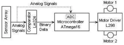
This robot is divided into several parts which are sensors, Analog-to-Digital Converter (ADC) and sensor circuit, processor, driver, actuators (motors and wheels) and chassis and body structure.
Figure 2.1: Line follower block diagram
8
Figure 2.2: Sensors location method
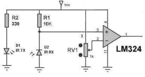
The received signals from the sensors are in analog form and must be converted to the digital form. Therefore, the circuit can be designed to send the sensors' signals to the processor, directly. Hence, the processing time can be managed just by using an external ADC. LM324 is good ADC have been used in this project. Two LM324 can support eight sensors.
Figure 2.3: Schematic of IR sensor
9
timers, UART, SPI, pull-up resistors, pulse width modulation, ADC, analog comparator and watch-dog timers are some of the features that will be found in AVR devices. One of the best AVR is the "At Mega 16" which has four ports for I/O and 16 MIPS speed in 16 MHz. The microcontroller power is 5V and it is better to use the 7805 regulator.
A robot needs a driver IC for controlling and giving power to the motors. The microcontroller sends a signal to the driver which acts as a switch. The microcontroller only sends a signal to the switch and then the switch must give required voltage to the motors. If the received signal by the driver is high, it will rotate the motors.
High speed motors and high sensitivity sensors circuit are used. ATMega16 and driver L298 were used to control direction and speed of motor. IC L298 is used in this project which can be used to control two motors. It is an integrated monolithic circuit in 15-lead Multiwatt and Power SO20 packages. It is a high voltage, high-current dual full-bridge driver designed to accept standard TTL logic levels and drive inductive loads such as relays, solenoids, DC, and stepping motors.
Figure 2.4: Driver and motor circuit