DOI: 10.12928/TELKOMNIKA.v13i1.129 41
Characteristics Analysis of Non-linear Torsional
Vibration in Engine and Generator Shafting System
Wei Zhang1*, Wenming Zhang1, Xuan Zhao1, Miaomiao Guo2 1
School of Mechanical Engineering, University of Science & Technology Beijing, Beijing China; 2
Automotive Engineering Research Institute, Beiqi Foton Motor Co. , Ltd., Beijing, China Telp:+86-010-62333637
*Corresponding author, e-mail: [email protected]
Abstract
The objective of this paper is to solve the non-linear torsional vibration problem of engine and generator shafting causing body structural vibration and noise in motorized wheel vehicle, where the engine and the generator connected directly. First, analysis the characteristics of the shafting system is conducted, besides the external shock excitation of engine and generator. Then, through lumped parameter model method, mathematical model of the non-linear torsional vibration was established, which could reflect the dynamic characteristics of the system. Analysis the effect of mechanical parameters and electromagnetic parameters on the shafting; and get the non-linear differential equations of the system torsional vibration, which expresses the relation between structural parameters, electromagnetic parameters and the system dynamic characteristics. And multiple scales method was used to solve the equations. Non-contact measurement method was used in the torsional vibration test. Finally, consistency of the results, indicate that the research method used is reliability and accuracy, and get the critical speed of the shafting torsional vibration.
Keywords: engine, gengrator, non-linear, torsional vibration, mathematical model
1. Introduction
The engine and the generator connected directly in motorized wheel vehicle power transmission system,which instead of the original drive shaft, transmission, differential, reducer, etc. There is a great different between this transmission system and the traditional mechanical transmission . The new characteristics of vehicle vibration are shown at present. Torsional vibration of the vibration system was a multi-complex vibration type. The engine and generator system was the local oscillator of vehicle vibration and noise [1]. The whole system was affected not only by the mechanical aspects, also by electromagnetic aspects, so torsional vibration excitation force type was changed significantly in engine and generator shafting system. In motorized wheel vehicle, the generator speed changed in high frequency, and the magnetic field varied significantly, so non-linear characteristics of torsional vibration performance were more evident, leading to more difficult in vibration and noise reduction [2]. Shafting torsional vibration control to ensure powertrain reliability and reduce vibration and noise have significant effect. so, research on the non-linear torsional vibration in motorized wheel vehicle has important significance.
the test method. Currently, research reference about the engine and generator system shafting non-linear torsional vibration in motorized wheel vehicle was less.
In this research, considering the working characteristics of motorized wheel vehicle, analysis the system shafting torsional vibration by using a lumped mass method. Analysis gas pressure in engine cylinder, reciprocating inertia force of connecting rod, self-excited moment of inertia caused by electromagnetic parameters of generator, and electromechanical coupling from electrical and mechanical interactions, so a nonlinear mathematical model of shafting torsional vibration obtained. And then the differential equations of non-linear torsional vibration were obtained. Multi-scale perturbation method was used on solve non-linear equation and analysis characteristics of resonance. Simulation and experimental validation were used to verify the correctness and reliability of mathematical model and analysis.
2. Torsional Vibration Modeling
2.1. Diagram of power transmission system
The engine and the generator connected directly in motorized wheel vehicle power transmission system,which instead of the original drive shaft, transmission, differential, reducer, etc. The structure shown in Figure 1.
Figure 1. Diagram of power transmission system
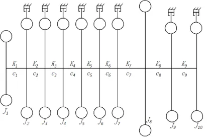
2.2. Differential equations of motion
The shafting system lumped parameter model shown in figure 2. Where J1 is the fan-driven inertia; J2、J3…J7 are moment of inertias of six crank mechanism in engine; J8 is the moment of inertia of the engine flywheel; J9 、J10 is the moment of inertia of the generator rotor;
K1 is the stiffness of the fan connection device; K2、K3…K7is the stiffness of spindle neck between two adjacent abduction; K8、K9 is the stiffness of the generator rotor. c1 the damping of fan-driven; c2 …c7 is the damping of each engine unit mass.
According to lumped mass model analysis in torsional vibration theory [5], engine and generator shafting nonlinear torsional vibration system was multiple degrees of freedom, so matrix form of motion equations could be written as:
J
C
K
T(1)
Where J is the inertia matrix; {φ} is the angular displacement matrix of each quality points in torsional vibration model; K is the stiffness matrix; C is the damping matrix; T is the incentive moment column vector, include gas pressure in engine cylinder, reciprocating inertia force of connecting rod, self-excited moment of inertia caused by electromagnetic parameters of generator, and electromechanical coupling from electrical and mechanical interactions. Because electromagnetic parameters contain the nonlinear term, the equation (1) were non-linear equations.
2.3. Kinetic equation
Kinetic equation for engine and generator system do fixed axis rotation shafting is as following [6]:
0 g j e
JCM M T (2)
Where J is the inertia matrix of the shafting; Mg is the torque for gas pressure in engine
cylinder; Mj is the torque for the force of connecting rod; Te is the excitation for electromagnetic parameters.
3. Incentive rationale analysis
Torque acting on a single crank:
g
sin cos
j
M P P r M t
(3)
Where Pg is the force for gas pressure in engine cylinder; Pj is the reciprocating inertia force of connecting rod; μ is the crank angle; is the angle between the centerline of the cylinder and the centerline of rod.
The function was a periodic function, in the four-stroke engine:
4
T
Whereω is angular velocity crankshaft.
3.1. Harmonic analysis of the force for gas pressure in engine cylinder Used Fourier series expansion the function M formula (3) :
m 1cos(
0)
2cos(2
0)
1cos(
0)
2cos(2
0)
M t
M
a
t
a
t
b
t
b
t
0 1
sin( )
m k k
k
M M k
t
(4)
Where Mm is the average torque; Mk is the amplitude of k times harmonic moments ; k is the initial phase angle,ω0 is baseband:
2 2
k k k
k k
k a arctg
b
0
2
T
That Mm only caused static torsional deformation to the crankshaft, didn’t cause excitation [7].So, formula (4) could be written as
1 1
1
sin( )
g
M M t
(5)
3.2. Reciprocating inertia force of connecting rod
Centrifugal force and reciprocating inertia force were two significant inertial forces of engine connecting rod. The action line of centrifugal force through the center of rotation of the crankshaft, so the torque on crankshaft was zero and no torsional vibration [8]. While the latter role at the center of the piston pin, through the connecting rod to the connecting rod journal, produced cyclical changes tangential torque on the crankshaft, so it was power source that torsional vibration caused. So reciprocating inertia moment could be written as:
2
1 3
2 sin sin 2 sin 3 sin 4
4 2 4 4
j j
M m r
(6)
Wheremj is the quality of the reciprocating motion component; Mj contains only 1,2, ...,
etc. integer harmonics, the higher the number, the smaller the magnitude of harmonic volume, and generally to four times.
3.3. Electromagnetic torque
In motorized wheel vehicle, engine output was coupled directly to the shaft of the generator, so the generator played part role of engine flywheel, which was great different with single engine. In this way, the engine could operate more effectively balance within the range of optimum efficiency. When dynamic analysis on the motor shaft, since the aspect ratio of the generator rotor portion was small, it could be considered as a rigid body. So in the calculation process, shear deformation of the shaft and effect of the lateral displacement on tensile and compressive deformation could be ignored, and rigid and elastic coupling could be ignored in node acceleration. Torsional vibration of motor shaft was a typical rotor system dynamics question, so external excitations were mainly parametric excitation of the generator [10], including the self-excited inertial force, the electromagnetic torque, and electromechanical coupling term.
According to the theory of electromechanical analysis shown that the system electromagnetic torque was:
e
N
T
(7)
2 cos [ cos
0
2 0 2
2
cos cos ]
1 2
d z
r l n n
N F t p
j n
F t p F t p d
i i
(8)
Where rd is the radius of the stator inner circle; lz is the length of the generator rotor;
、
α β is the angle with the vertical direction when the gap is certain value or the minimum value; is power angle; ξ is power factor angle; is the effective relative eccentric of generator rotor; Fj、Fi1、Fi2 is the fundamental amplitude of the rotor magnetic potential、positive sequence and negative sequence magnetic potential of electronic; ω is the frequency of generator rotor; P is the pole pairs of synthesis magnetic; n is the order of Taylor series expansion.
Under the effect of the electromagnetic torque, non-linear torsional vibration of shafting have a great relationship with stiffness and damping of generator rotor, both of which could be written as:
2 2 2
2
(
1)
12
di di di ndi di
d
E h l
n
f
k
r
(9) 2 2 ( 1) 2 ddi i i
m n c k n
(10)Where i=1、2; md is the total mass of stator; hd、ld is the yoke thickness and length of stator; Ed
is the modulus of elasticity; n is the reeb order; fnd is the ratio coefficient between stator yoke
thickness and the radius of the inner circle; is the damping ratio between stator core and cabinet.
4. Modeling and solving of non-linear torsional vibration 4.1. Modeling
By the formula (1), (2) and (7) and driving forces analysis, shafting system torsional vibration dynamic equation could be written as:
1 2
(
d)
g j e d T d rJ
C C
K
M
M
T
K
K
J
(11)
whereJ=diag
J J1, 2...J10
is inertia matrix;
1 2... 10
T 、 is the angular displacement of each mass point of Torsional vibration model;
1 1
1 1 2 2
8 8 9 9
9 9
=
k k
k k k k K
k k k k k k
is the stiffness matrix;
1 2 3 4 5 6 1 2
=diag 0, , , , , , , 0, ,
d d d
C c c c c c c , c c is the external damping matrix;
6
0 1 1
1
0, sin( ) , 0, 0, 0
T
g g
M M M t
1 1
1 1 2 2
8 8 9 9
9 9
=
c c
c c c c C
c c c c c c
is the internal damping matrix;
6 2
2 1 2 1 2 1
1
2 1
1 3
{0, [ sin( ) sin 2( ) sin 3( )
4 2 4
2
sin 4( )],0,0,0}
4
j j
T
M m r t t t
t
1 2 T d dK K and Jr, Kd1 and Kd2 reflect the impact of generator on the torsional vibration, which are electromechanical coupling terms, as shown in the formula (11); Jr is the self-excited inertial force of shafting, which is electromechanical coupling term too. These terms associate with the structure parameters and electromagnetic parameters of the shafting system.
The self-excited inertial force could be written as:
0 0
0 0 1
2 1 2 0 1 2 0
cos cos cos
1 2
cos cos cos cos
1 2
cos sin
g j
r d d
T
d d d
T T T T T
d d d d d d d d
M M
J J J F t p J F t p t
j i
J
J F t p t F t p t J K
i j
J K J K K K t J K K t
The self-excited inertial force of shafting and electromechanical coupling terms were nonlinear terms, so (11) were the non-linear equations. Multi-scale perturbation method was used to solve the non-linear equations [12].
Shafting worked under the action of alternating loads, by the action of Mg、Mj、Te, which were periodic functions, Fourier series expansion were used:
0 1 1
1
sin(
)
g g
M
M
t
(12)0 2 2
1
sin( )
j j
M M t
(13)0 3 3
1
sin(
)
e e
T
T
t
(14)When the shafting speed was n, so:
3
=
30
n
k、=0、1、2……
Where ω0 is the natural frequency of the engine and generator shafting; since the first eight natural frequencies relatively large impact on the shafting, generally only analyzed the impact of the order. During the engine and generator shafting operation, the torque for gas pressure in engine cylinder, the torque for the force of connecting rod and the excitation for electromagnetic parameters, which could exist alone or in combination and simultaneously to meet the resonance condition.
4.2. Solving
From the non-linear vibration theory, when the frequency of the shafting excitation force to meet ≈iω0, shafting torsional resonance occurred [13], which could be written as:
0
Where, is the detuning parameter, is the excitation frequency of shafting. When ≈ω0, called primary resonance;
When 3 =ω0+ , that ≈ω0/3, called super harmonic resonance; When =ω0+ , that ≈ω0, called harmonic resonance;
When 0= n1n2n3 , called combination resonance,where n1、n2、n3= 、 、1 2 3. The analysis showed that multiple resonance conditions existed, when the shafting working in low load operation, combination resonance occurred at high probability, so here select a combination resonance solved. When 2 1+3≈ω0satisfied, shafting non-linear torsional resonance might occur in case of excitation, using multi-scale perturbation method for solving [14],[15]:
Solution of formula (11) was assumed as:
,
0
0,
1
1
0,
1
x t
x T T
x T T
(15)
Put formula (15) into the equation, to solve the coefficient, the solution could be obtained:
0 12 2
0 1 0 0 1 1 0
1
exp(
)
(
) exp(
) exp(
)
2
gx
A T
i T
M
i
i T
0 0
2 2 2 2
2 2 2 0 3 3 3 0
1
1
(
) exp(
) exp(
)
(
) exp(
) exp(
)
2
M
j
i
i T
2
T
e
i
i T
CC
(16)
And satisfied the combination resonance condition:2 1 3 0 ,could be written as: 0 2 1 3
2
1 3
T0
0 T0
0 0T
T0 (17)Taking the first eight-order shafting vibration to be solved, the solution of the state equation could be obtained as follows:
0 1 1 1
0 2 2 2 0 3 3 3
( )
cos
cos
cos
cos
r r r r r r
r r r r
t
A
t
B
t
B
t
B
t
Where r=1、 、2 3…8; ωr is r order of system natural frequency; Ar and θr are to be
evaluated; φrk is r order phase angle; 0 20 2
2( )
r rk rk
k a B
,a0rk is r-order amplitude, k=1、 、2 3.
Similarly, other resonance conditions could be obtained , so the first approximate solution of the shafting system was:
3 0
1
( )
cos
cos
r r r r rk rk rk
k
t
A
B
t
(19)
Through formula (19) could be found that in non-linear conditions of the engine and generator shafting system, when 1、 2、 3 satisfied the resonance condition, the shafting system could resonate. The amplitude of the response of the resonant system connected with the amplitudes of the force for gas pressure in engine cylinder, reciprocating inertia force of connecting rod and electromagnetic excitation parameters.
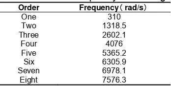
Table.1 Natural frequency of shafting Order Frequency rad/s
One 310 Two 1318.5 Three 2602.1
Four 4076 Five 5365.2 Six 6305.9 Seven 6978.1
Eight 7576.3
Table 1 shows the eight bands natural frequency of shafting system torsional vibration. After three order, natural frequency was greater than 3000rad/s, generally resonance does not occur, actually considered the first three order to study[16].
4.3. Simulation Analysis
When τ1=50Hz,τ3=110Hz, the second natural frequency of the shafting system is ω02=210Hz, which meet the combination resonance condition 2τ1+τ3≈ω0, the engine speed was 1900rpm. According to the formula (16) , through the engine and generator shafting system simulation, obtained time-domain response and frequency-domain response, which in Figure 3 and Figure 4:
Figure 4. Curve of frequency domain
From figure 4 that shows the frequency domain response, the first crest frequency is 50Hz, and the corresponding amplitude is 47.65μm, which generated by the electromagnetic parameters incentives of the shafting system. The second crest frequency is 110Hz, and the corresponding amplitude is 17.66μm, which generated by the force for gas pressure in engine cylinder of the shafting system. The results show that, when certain conditions are met, under the joint action of the electromagnetic parameters incentives and the force for gas pressure in engine cylinder, non-linear resonances appear in shafting system [17].
5. Test Analysis and Verification
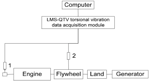
In order to verify the accuracy and reliability of non-linear torsional vibration model and simulation of engine and generator shafting, shafting system torsional vibration test was used. Non-contact type torsional vibration measuring method was used, which measuring unit was not mounted directly on the shafting, using the engine flywheel or the free end gear tray. Torsional vibration signals collected by magnetic sensors[18],[19]. LMS-QTV was used to convert and pickup torsional vibration signal. Accuracy of this kind of measurement method was high, the simply operation method, quickly test response, and very small impact of the testing device itself on the vibration shafting [20]. In Figure 5, diagram of torsional vibration measuring device was shown.
Figure 5. Diagram of torsional vibration measuring equipment
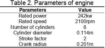
Table 2. Parameters of engine
Parameters Value
Rated power 242kw
Rated speed 2100rpm
Number of cylinders 6
Cylinder diameter 0.114m
Stroke factor 2
Crank radius 0.201m
TFBPW-355 brushless synchronous generator of Lanzhou motor limited liability was chosen in the test, and the parameters shown in Table 3:
Table 3. Parameters of generator
Parameters Value
Rated power 230kVA
Rated frequency 120Hz
Rated speed 1800rpm
Rated voltage 660V
Rated current 201A
During the test, the engine and generator system run at full load condition [21]. The shafting uniformly accelerated from idle speed 750rpm to the rated speed 2100rpm. Torsional vibration data acquisition equipment recorded every 50 rpm. Then uniformly decelerated from rated speed to idle state. So repeatedly, the most representative of the data was selected to read torsional vibration data.
6. Experimental results and analysis 6.1 Torsional Vibration Analysis
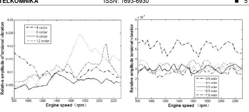
The engine was inline 6-cylinder and 4-stroke, harmonic order of disturbance torque that might provoke shafting resonance, main harmonic orders were 1,3,5,7,9, etc. Strong harmonic orders were 1.5,3.5,4.5,5.5, 6.5, 7.5, etc. The generator was rigidly mounted directly to the output of the engine crankshaft, the generator rotor simultaneously played the role of flywheel [22],[23].
(b)Analysis diagram of 4、 、 、6 8 12 harmonic (d)Analysis diagram of 3.5、4.5 5.5 6.5 、 、 、
7.5 powerful harmonic
Figure 6. Analysis diagram of harmonic
Figure 6 (a) shows that 1,1.5,2 harmonic orders analysis charts of the engine and generator shafting torsional vibration. There can be seen that the maximum amplitude of torsional resonance at 1.5 order, then the engine speed is 1942rpm, corresponding frequency of 45.55Hz. At the same time , when the shafting system running at full load and low speed, torsional vibration amplitudes of 1 and 2 orders are large, but its΄t the natural frequency of the shafting itself. From the above analysis shows that caused by incentive interference harmonic order that relatively strong. Figure 6 (b) shows that 4,5,8,12 harmonic orders analysis charts of the engine and generator shafting torsional vibration. As can be seen from the Figure 6(b), when the shafting working at 1716rpm, the crest appears in 6 order, and then the corresponding frequency is 171.6Hz. When the shafting working at 2065rpm, the crest appears in 12 order, and then the corresponding frequency is 413Hz. Through analysis, resonance phenomenon occurs at 6 and 12 orders, but the amplitudes of torsional vibrations are small and within the allowable range. Figure 6 (c) shows that 3,5,7,9 main harmonic orders analysis charts of the engine and generator shafting torsional vibration. Amplitudes of torsional vibration of each strength harmonic order change relatively flat and small within the entire speed range. Among them, 3 order in the shafting speed 1325rpm, amplitude crest occur, but the relative torsional vibration amplitude is 0.03 or less, and the other sub-harmonic amplitudes are very small. Figure 6 (a) shows that 3.5, 4.5, 5.5, 6.5, 7.5 powerful harmonic orders analysis charts of the engine and generator shafting torsional vibration. Torsional amplitude of each harmonic order is relatively small. Although there will be wave peaks, the relative amplitudes are less than 0.006, which are more smaller under other speed and order.
6.2 Non-linear Analysis
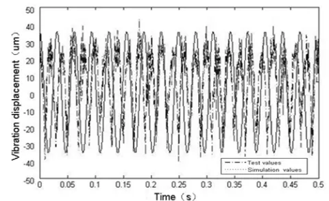
Figure 7. Curve of time domain
Figure 8. Curve of frequency domain
Figure 7 shows the time-domain response curve, which shows the simulation results and experimental results are basically consistent with trends. From Figure 8 which shows frequency-domain response curve, the frequency at the first crest is 51.2Hz, and corresponding to the amplitude is 42.35μm; corresponding frequency at the second crest is 109.5Hz, and the corresponding to the amplitude is 14.35μm. Through above analysis, the first crest is excited by the electromagnetic parameters of shafting produce; and the second crest is suffered by the shafting system gas explosion pressure generated. The simulation results and experimental results show that the engine and generator shafting system in the motorized wheel vehicle in the role of electromagnetic excitation of generator, force for gas pressure in engine cylinder and force of connecting rod, resonance phenomenon occurs under the combined effect of non-linear parameters and external excitation.
7. Conclusions
To solve the mathematical model and analysis solution of non-linear torsional vibration of the engine and generator shafting system in the motorized wheel vehicle, through simulation and experimental verification, conclusions as the following:
(1) The establishment of lumped mass method shafting system dynamic equations of nonlinear vibration model, using multi-scale analysis method for solving nonlinear equations torsional vibration analysis of the approximate solution under different resonance conditions, the model simulation and experimental results illustrate the consistency correctness nonlinear mathematical model, and can better reflect the system torsional vibration characteristics. (2) The results showed that the engine and the generator shafting system torsional vibration
resonance there are several forms, so when the design calculations, need to be analyzed according to the actual working conditions, to avoid prolonged work in the vicinity of the critical speed.
(3) The mathematical model reflects the effects of the dynamic performances, structural parameters and electromagnetic parameters of the shafting system on shafting torsional vibration. Meanwhile electromechanical coupling term reflects the intrinsic link between the three. The model reflects the shafting dynamic performances and vibration law. Further research on vibration and noise reduction in motorized wheel vehicle shafting system, which have guiding significance and application value.
Acknowledgment
This work was supported by the National High Technology Research and Development Program of China (863 Program) (Grant NO: 2011AA060404, Underground intelligent mining truck).
References
[1] Bedoor BO, Moustafa KA, Hussain KM. Dual dynamic absorber for the torsional vibrations of synchronous motor-driven compressors. Journal of sound and vibration.1999; 220(4): 729-748. [2] Fukuda S, Eto H. Development of fracture splitting connecting rod. JSAE Review. 2002; 23(1):
101-104.
[3] Charles P, Sinha JK, Gu F, et al. Detecting the crankshaft torsional vibration of diesel engines for combustion related diagnosis. Journal of Sound and Vibration. 2009; 321(3): 1171-1185.
[4] Boysal A, Rahnejat H. Torsional vibration analysis of a multi-body single cylinder internal combustion engine model. Applied Mathematical Modelling.1997; 21(8): 481-493.
[5] Östman F, Toivonen HT. Active torsional vibration control of reciprocating engines. Control Engineering Practice. 2008; 16(1): 78-88.
[6] Brusa E, Delprete C, Genta G. Torsional vibration of crankshafts: effects of non-constant moments of inertia. Journal of Sound and Vibration. 1997; 205(2): 135-150.
[7] Li Z, Gui CL, Sun J. Review of the researches on vibrations of crankshaft system in internal combustion engines. Transactions of Chinese Society for Internal Combustion Engines. 2002; 20(5): 469-474.
[8] Ma C, Zuo SG, Tan QW, et al. Non-linear torsional vibration model of a PMSM for electric driven vehicle. Journal of Vibration and Shock. 2013; 32(12): pp.131-134.
[9] Christopher S, Keeney, Shan S. Prediction and control of heavy duty powertrain torsional vibration. SAE922481: 279.
[10] Zhou CY, Xu ZC, You GY, et al. Analysis of rotor dynamics of engine-generator unit system. Journal of Vibration and Shock. 2010; 9(s1):163-167.
[11] Liu H, Cai Z, Xiang C. Dynamic characteristics of vehicular planetary gears influenced by engine excitation and backlash based on nonlinear torsional vibration model. Springer Berlin Heidelberg, 2013: 115-126.
[12] Deighan TP, Whitehead T. Driveline vibration analysis for successful clutch spring pack design for a 4 cylinder motorcycle engine. SAE Technical Paper. 2013.
[13] Szczepaniak, Kesy A, Kesy Z. Damping performance of power transmission system with hydraulic torque converter. Vehicle System Dynamics.1991; 20: 473-479.
[14] Henao H, Kia SH, Capolino GA. Torsional-vibration assessment and gear-fault diagnosis in railway traction system. Industrial Electronics, IEEE Transactions on. 2011; 58(5): 1707-1717.
[16] Mourelatos Z. Crankshaft system model for structural dynamic analysis of internal combustion engines. Computers & Structures. 2001; 6: 102-107.
[17] Shangguan WB, Chen C, Duan XC, et al. Modeling and experimental analysis of torsional vibration in engine crankshaft system. Journal of Vibration, Measurement &Diagnosis. 2012; 32 (4): 560-567. [18] Nagar A, Chokkalingam V, Umashankar N, et al. Improvement in crank train torsional vibration (TV)
performance of multi-cylinder diesel engine. SAE Technical Paper. 2013.
[19] Li XQ, Wang G, Lv BL, et al. Calculation method and characteristics analysis of torsional vibration of diesel generating set shaft system in short circuit condition. Chinese Internal Combustion Engine Engineering. 2013; 34(2): 18-23.
[20] Manin L, Dufour R, Schultz S. Pulley torsional vibration damper characterization. Mechanics & Industry. 2013; 14(2): 151-155.
[21] Licari J, Ugalde-Loo CE, Ekanayake JB, et al. Damping of torsional vibrations in a variable-speed wind turbine. Energy Conversion, IEEE Transactions on. 2013; 28(1): 172-180.
[22] Monroe RJ, Shaw SW. Nonlinear transient dynamics of pendulum torsional vibration absorbers—part I: theory. Journal of Vibration and Acoustics. 2013; 135(1): 11-17.