DOI: 10.12928/TELKOMNIKA.v15i1.5002 220
Performance of Groundplane Shaping in Four-Element
Dualband MIMO Antenna
Subuh Pramono*1, Tommi Hariyadi2, Budi Basuki Subagio3 1,3
Department of Electrical Engineering, Politeknik Negeri Semarang, Semarang, Indonesia
2Department of Electrical Engineering, Universitas Pendidikan Indonesia, Bandung, Indonesia
*Corresponding author, e-mail: [email protected]
Abstract
This work presents performance of groundplane shaping and its effect in four element dualband multiple input multiple output (MIMO) antenna. This proposed four element dualband MIMO antenna consists of four bowtie dipole antenna which operates at 1800 MHz (low frequency) and 2300 MHz (high frequency). This proposed four element dualband MIMO antenna occupies a 270 x 210 x 100 mm3 of FR 4 substrate. We use four types of groundplane pattern i.e. full groundplane, cornered spatial groundplane, crossed middle groundplane, and spiral groundplane. These various grounplane patterns influence the performance of main parameters of dualband MIMO antenna. Cornered spatial groundplane pattern yields
a largest bandwidth (VSWR ≤ 2) 282 MHz or 15.24% of center frequency at low frequency. Full
groundplane pattern creates 135.2 MHz at high frequency. In addition, cornered spatial groundplane pattern also generates a lowest VSWR that is valued 1.21 at both low frequency and high frequency. The S parameters, basically both cornered spatial and full groundplane pattern produce a better return loss than two others. All four groundplane patterns deliver equally a mutual coupling parameter.The last, this proposed four element dualband MIMO with various groundplane patterns gives a good farfield properties i.e. gain, radiation pattern, H-E field.
Keywords: groundplane, MIMO antenna, dualband, mutual coupling, S parameter, bandwidth
Copyright © 2017 Universitas Ahmad Dahlan. All rights reserved.
1. Introduction
In recent years, telecommunication technology is moving toward into high speed data rate communication. Particularly, cellular telecommunication now is 4th generation which is 300 Mps uplink dan 75 Mbps downlink data rate. Many techniques have been developed on digital communication that addressed to support high speed data rate. One of important technique is antenna system. The antenna system has been deeply developed. Recently, receiver and transmitter use multiple antennas, it is well known as multiple input multiple output (MIMO) antenna system. The MIMO antenna system has an advantage in term of spatial multiplexing and spatial diversity. Spatial diversity provides stronger link robustness by increased signal to noise ratio. Spatial multiplexing effectively increases a link capacity [1]. A wider bandwidth is absolutely needed in recent celluler telecommunication technology. Various techniques were explored to enhance the bandwidth, such as using feed optimization, ground plane slits and investigated the effects of shaped groundplane on impedance and bandwidth parameters. This proposed MIMO antenna system consists of four antenna elements. Single antenna element is constructed by bowtie dipole antenna with an integrated balun that is dualband 1800 MHz and 2300 MHz. Bowtie dipole antenna with integrated balun have been proven that can to provide a wider bandwidth [8]. This MIMO antenna operates dualband frequencies 1800 MHz and 2300 MHz which are cellular communication application.
crossed middle groundplane, and spriral groundplane. Specifically, we focus on the effects of various patterns of groundplane shaping on main antenna parameters i.e. VSWR, bandwidth, gain, mutual coupling, and radiation pattern. This dualband MIMO antenna operates with center frequency 1850 MHz and 2350 MHz. This work comprises four sections, section I is introduction. Section II detail explains three subjects which are single element of bow tie dipole antenna design, four element dualband MIMO antenna design, various patterns of groundplane shaping. Section III discusses and analyses numerically simulated results of antenna parameters. Section IV is conclusion.
2. Multiple Input Multiple Output (MIMO) Antenna
This MIMO antenna comprised four antennas element. A single antenna element on this proposed four element dualband MIMO antenna is designed using by bowtie dipole antenna characteristic and equivalent dielectric constant can be estimated by these below formulas [9]:
(1)
(2)
(3)
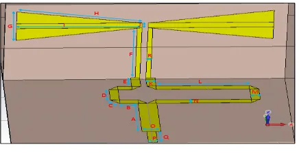
L is length of bowtie dipole antenna. Zt is characteristic impedance of the bowtie dipole antenna. is bowtie dipole antenna angle. W is width of bowtie dipole antenna. is equivalent dielectric constant. is dielectric constant of substrate, d is thickness of the substrate. The arm dipole and bowtie dipole are vertically placed to groundplane. Complete geometrical design of single bowtie dipole antenna is depicted at Figure 1. Furthermore, Table 1 describes a precisely size of single bowtie dipole antenna.
Figure 1. Single Bowtie Dipole Antena Design
Table 1. Single Bowtie Dipole Antenna Parameters
Parameter A B C D E F G H I J K L M N O P Q R
Value (mm) 24.5 6 4.1 9 7 30 16.9 40.6 40 2.9 2.9 30.5 2.9 2.9 5.5 2.9 9.5 1.5
2.2. Four Element Multiple Input Multiple Output (MIMO) Dualband Antenna
Complete geometrical design of four element dualband MIMO antenna is shown at Figure 2. This proposed antenna occupies a 270 x 210 mm2 of FR 4 substrate (
(Table 2). It works at dualband frequencies with center frequency 1850 MHz and 2350 MHz. This four element dualband MIMO antenna generates four S parameters. The S parameters are described as below matrix [10].
(4)
ASub
BS ub
CSub DSub
ESub FSub
Figure 2. Geometrical of Four Element MIMO Dualband Antenna Design
Table 2. Four element MIMO Dualband Antenna Parameters
Parameter Asub Bsub Csub Dsub Esub Fsub
Value (mm) 270 210 90 90 110 50
2.3. Groundplane Shaping
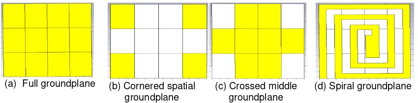
A ground plane is an electrically conductive surface. Groundplane is placed at the bottom side of this proposed antenna. This research uses four patterns of groundplane shaping i.e. full groundplane, cornered spatial groundplane, crossed middle grounplane and spiral groundplane which are detail described at Figure 3.
(a) Full groundplane (b) Cornered spatial groundplane
(c) Crossed middle groundplane
(d) Spiral groundplane
Figure 3. Four Patterns of Groundplane Shaping
3. Results and Analysis
In this section, we will provide a discussion and analysis of groundplane shaping effects in four element dualband MIMO antenna performance. The groundplane shapings affect the antenna parameters i.e. bandwidth, mutual coupling, VSWR, gain and radiation pattern. The proposed four element dualband MIMO antenna was designed using the CST studio suite. 3.1. Voltage Standing Wave Ratio (VSWR) & Bandwidth
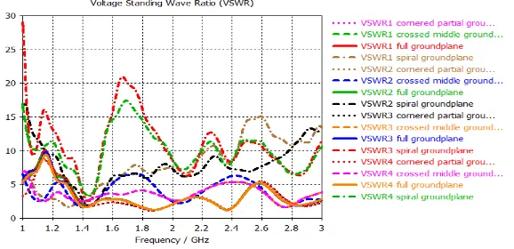
Based on Figure 4 and Table 3 shows that simulation VSWR results in various groundplane shaping is in range of 1.21 until 13.16 both at low frequency (1800 MHz) and high frequency (2300 MHz). The lowest VSWR is obtained from cornered spatial groundplane pattern at low frecuency (1800 MHz). Meanwhile, the highest VSWR is produced from spiral groundplane pattern at low frecuency (1800 MHz). It means that the reflected voltage is only 9.5 % of forwarded voltage at the lowest VSWR. In case of the highest VSWR, almost 85.8 % of forwarded voltage is reflected. Furthermore, cornered spatial groundplane pattern generates a widest bandwidth (VSWR < 2) 282 MHz at low frequency (1800 MHz). It is 15.2 % of center frequency. Meanwhile, full groundplane pattern yields a largest bandwidth (VSWR <2) 135.2 MHz at high frequency (2300 MHz) which is 5,7 % of center frequency. Whereas, both crossed middle groundplane pattern and spiral groundplane pattern can not meet the bandwidth VSWR< 2. The simulation VSWR and bandwidth (VSWR <2) results are detail depicted at Figure 4 and Table 3-4.
Figure 4. VSWR profile
Table 3. VSWR at Low Frequency (1800 MHz) and High Frequency (2300 MHz)
Full groundplane Cornered spatial groundplane Crossed middle groundplane Spiral groundplane
F(MHz) Ant VSWR F(MHz) Ant VSWR F (MHz) Ant VSWR F(MHz) Ant VSWR
1800 1 1.42 1800 1 1.21 1800 1 5.71 1800 1 6.27
1800 2 1.42 1800 2 1.21 1800 2 5.71 1800 2 5.94
1800 3 1.42 1800 3 1.21 1800 3 3.93 1800 3 14
1800 4 1.42 1800 4 1.21 1800 4 3.93 1800 4 13.16
2300 1 1.33 2300 1 1.41 2300 1 5.6 2300 1 9.6
2300 2 1.33 2300 2 1.41 2300 2 5.6 2300 2 8.24
2300 3 1.33 2300 3 1.41 2300 3 5.17 2300 3 10
2300 4 1.33 2300 4 1.41 2300 4 5.17 2300 4 8.52
Table 4. Bandwidth VSWR ≤ 2
Full groundplane Cornered spatial groundplane Crossed middle groundplane Spiral groundplane
F(MHz) Ant BW(MHz) F(MHz) Ant BW(MHz) F(MHz) Ant BW(MHz) F(MHz) Ant BW (MHz)
1800 1 235.5 1800 1 282 1800 1 0 1800 1 0
1800 2 235.5 1800 2 282 1800 2 0 1800 2 0
1800 3 235.5 1800 3 282 1800 3 0 1800 3 0
1800 4 235.5 1800 4 282 1800 4 0 1800 4 0
2300 1 135.2 2300 1 122 2300 1 0 2300 1 0
2300 2 135.2 2300 2 122 2300 2 0 2300 2 0
2300 3 135.2 2300 3 122 2300 3 0 2300 3 0
3.2. S Parameter
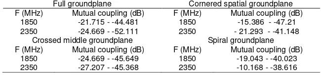
This proposed four element dualband MIMO antenna creates four port S parameters. The S parameters include a return loss (S11,S22,S33,S44) and a mutual coupling (S12,S13,S14,S21,S23,S24,S31,S32,S34,S41,S42,S43). Based on Figure 5, we can see the return loss results that cornered spatial groundplane pattern produces the best return loss in range of -22 dB until -26 dB at low frequency (1800 Mhz). At the high frequency (2300 MHz), full grounplane pattern yields the best return loss in range of -17 dB until -20 dB. Both crossed middle groundplane pattern and spiral groundplane pattern generates a worse return loss in range of -2 dB until -5 dB. Figure 6 shows the simulation results of mutual coupling. Basically, all various groundplane patterns, both low frequency and high frequency, creates equally mutual coupling results in range of -10.168 dB until -52.111 dB (Table 5). With all obtained values of mutual coupling are relative high that means four element antennas in this proposed dualband MIMO antenna design are independently existence. Decreasing of groundplane can reduce the fringing effect on the edge.
Figure 5. Return Loss Curves (S11, S22, S33, S44)
Figure 6. Mutual Coupling Curves (S12,S13,S14,S21,S23,S24,S31,S32,S34,S41,S42,S43)
Table 5. Mutual Coupling at Low Frequency and High Frequency in all Various Groundplane Patterns
Full groundplane Cornered spatial groundplane
F (MHz) Mutual coupling (dB) F (MHz) Mutual coupling (dB)
1850 -21.715 - -44.481 1850 -15.386 - -47.21
2350 -24.669 - -52.111 2350 - 21.293 - -41.148
Crossed middle groundplane Spiral groundplane
F (MHz) Mutual coupling (dB) F (MHz) Mutual coupling (dB)
1850 -24.669 - -45.649 1850 -19.043 - -40.023
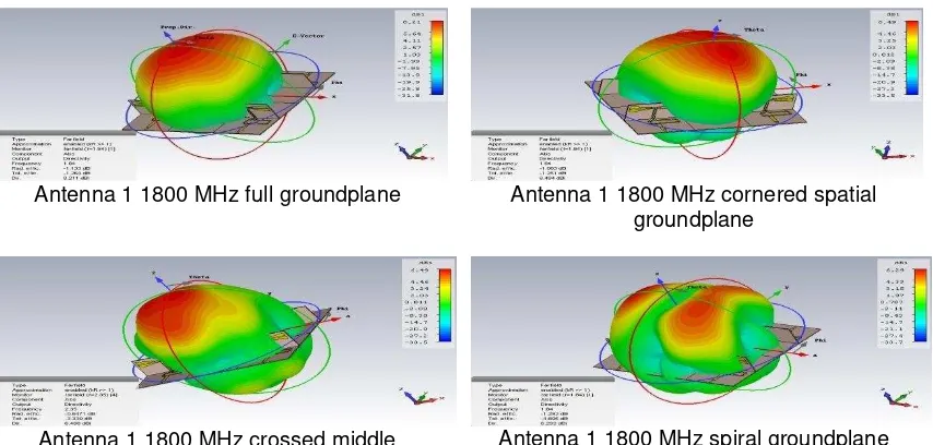
3.3. Radiation Pattern, Gain & H-E Field
Figure 7, Figure 8 and Table 6 explains a simulation result of farfield properties which is including 2D ( two dimensional) magnetic field (H) – electrical field (E), 3D ( three dimensional) radiation pattern, and antenna gain, respectively. All farfield properties of four element dualband MIMO antenna are simulated with all various groundplane patterns at both low frequency and high frequency. Based on Figure 8 and Table 6, shows that both full groundplane pattern and cornered partial groundplane pattern yield a better gain than spiral groundplane pattern and crossed middle groundplane pattern.
Full groundplane pattern and cornered partial groundplane pattern gives a gaining in range of 6.59 dBi until 8.45 dBi. Meanwhile, spiral groundplane pattern and crossed middle groundplane pattern creates a lower gaining than two previous patterns.It is lower valued in range of 4.66 dBi until 7.18 dBi.
Figure 7. 2D of Magnetic Field (H) and Electrical Field (E)
Antenna 1 1800 MHz full groundplane Antenna 1 1800 MHz cornered spatial groundplane
Antenna 1 1800 MHz crossed middle groundplane
Antenna 1 1800 MHz spiral groundplane
Table 6. Dualband MIMO Antenna Gain with Various of Groundplane Pattern patterns give effect on main parameters of proposed MIMO dualband antenna. Cornered spatial groundplane pattern yields widest bandwidth, 282 MHz or 15.24 % of center frequency, at low frequency (1800 MHz) while full groundplane pattern creates a 135.2 MHz bandwidth at high frequency (2300 MHz).In addition, cornered spatial groundplane pattern also generates a lowest VSWR, it is 1.21, both low frequency and high frequency. Second, cornered spatial and full groundplane pattern also produces a better return loss than both spiral and crossed middle groundplane pattern.Third,all various groundplane patterns give a equally value of mutual coupling. This proposed four element MIMO dualband antenna with four groundplane patterns also generates good farfield properties i.e. gain, radiation pattern, H-E field.
References
[1] Pramono S, Hariyadi T. Performance Analysis of Transceiver 4 × 4 Space Time Block Coded MIMO-OFDM System. Proceedings of the 2nd International Conference on Information Technology, Computer, and Electrical Engineering: Green Technology Strengthening in Information Technology, Electrical and Computer Engineering Implementation (ICITACEE). Semarang. 2015: 426-429. [2] Zhang C, Fathy AE. Development of an Ultra-Wideband Elliptical Disc Planar Monopole Antenna with
Improved Omnidirectional Performance using a Modified Ground. IEEE Antennas and Propagation Society International Symposium. Alburqueque. 2006: 1689-1692.
[3] Ali A, Al Sajee D, Karim AH. Improving Bandwidth Rectangular Patch Antenna Using Different Thickness of Dielectric Substrate. ARPN Journal of Engineering and Applied Sciences. 2011; 6(4). [4] Malviya L, Panigrahi RK, Kartikeyan MV. A 2 x 2 Dual-Band MIMO Antenna with Polarization
Diversity for W ireless Applications. Progress in Electromagnetics Research C. 2016; 61: 91-103. [5] Hong-Min L, Wong-Sang C. Effect of Partial Ground Plane Removal on the Radiation Characteristics
of a Microstrip Antenna. Wireless Engineering and Technology. 2013; 4: 5-12.
[6] Zhi NC, Terence SPS, Xianming Q. Small Printed Ultrawideband Antenna with Reduced Ground Plane Effect. IEEE Transactions on Antennas and Propagation. 2007; 55(2).
[7] John M, Evans JA, Ammann MJ, Modro JC, Chen ZN. Reduction of ground-plane-dependent effects on microstrip-fed printed rectangular monopoles. IET Microw. Antennas Propag. 2008; 2(1): 42-47. [8] Shi-Wei Q, Jia-Lin L, Quan X. Bowtie Dipole Antenna with Wide Beamwidth for Base Station
Application. IEEE Antennas and Wireless Propagation Letters. 2007; 6.
[9] Xin S, Bi-ying L, Lan-zhi Z. Channel Construction and Moving Target Imaging for UWB MIMO through the Wall Radar. Journal of Electronics & Information Technology. 2014; 36(8): 1946-1953. [10] Pramono S, Sugihartono. Three, four transmit antennas space time block coded MIMO in Rayleigh