PRELIMINARY INVESTIGATION OF AUTOMOBILE
HYDRAULIC TRANSMISSION SYSTEM
AHMAD ZAKI BIN ABD RAZAK
UNIVERSITI TEKNIKAL MALAYSIA MELAKA
Preliminary Investigation of Automobile
Hydraulic Transmission System
Thesis submitted in accordance with the requirements of the Universiti Teknikal Malaysia Melaka for the Degree of Bachelor of Engineering
(Honors) Manufacturing (Process)
By
Ahmad Zaki Bin Abd Razak
UTeM Library (Pind.1/2005)
mengaku membenarkan tesis (PSM/Sarjana/Doktor Falsafah) ini disimpan di Perpustakaan Universiti Teknikal Malaysia Melaka (UTeM) dengan syarat-syarat kegunaan seperti berikut:
1. Tesis adalah hak milik Universiti Teknikal Malaysia Melaka.
2. Perpustakaan Universiti Teknikal Malaysia Melaka dibenarkan membuat salinan untuk tujuan pengajian sahaja.
3. Perpustakaan dibenarkan membuat salinan tesis ini sebagai bahan pertukaran antara institusi pengajian tinggi. atau kepentingan Malaysia yang termaktub di dalam AKTA RAHSIA RASMI 1972)
(Mengandungi maklumat TERHAD yang telah ditentukan oleh organisasi/badan di mana penyelidikan dijalankan)
(TANDATANGAN PENULIS)
APPROVAL
This thesis submitted to the senate of UteM and has been accepted as partial fulfillment of the requirements for the degree of Bachelor of Manufacturing
Egineering (Manufacturing Process). The member of the supervisory committee is as follow:
………. Project Supervisor
DECLARATION
I hereby, declare this thesis entitled “Preliminary Investigation of Automobile Hydraulic Transmission System” is the results of my own research except as cited
in the reference.
Signature : ………
Author’s Name : ………
ABSTRAK
ABSTRACT
DEDICATION
ACKNOWLEDGEMENTS
Assalamualaikum w.b.t. and warm greeting,
First and foremost, I would thank ALLAH SWT for His blessings and for the strength given to me to finish this project.
Next, I would like to place my gratitude to the ones that contributed to the success of this project. I wish to acknowledge and express my gratitude and appreciation to my supervisor, Mr. Sivarao for his supervision, encouragement, suggestion and assistance through the research. A million appreciations to the examiner of this project, En Ir Hasolan Haery Ian Pieter for evaluating this project. I would also like to thank my parents, Mr. Abd Razak bin Yaacob and Madam Rubiah binti. Said where their continuous encouragement, faith and confidence besides moral support which has never let me down.
I would also like to express my biggest thanks to FKP especially Dean of Faculty of Manufacturing Engineering, Professor Dr. Mohd Razali b. Muhamad; Head of Manufacturing Deparment, En. Mohd Hadzley bin Abu Bakar and all the lecturers in the Faculty of Manufacturing.
TABLE OF CONTENTS
1.5 Overview of the Hydraulic Component………..……….……10
1.5a Hydraulic Pump………..…………..……..10
i. Hydraulic Pump Theory………...……….…..13
1.5b Hydraulic Motor………...……….….21
i.. Factors Involving Hydraulic Motor………...………….…21
ii. Selecting the Hydraulic Motor………...……....23
iii Sizing the Hydraulic Motor………..……….…23
1.5c Control Valves…………..………..…………25
i. Ports and Position………...………...25
1.5d Hydraulic Fluid……….27
i Influential Factors Involving the hydraulic fluid…………28
2. LITERATURE REVIEW………...31
3.7 Hydraulic circuit designed………….……….…….45
3.8 Hydraulic Transmission simulation………..…...46
3.9 Simulation analysis……….…….47
i) Analysis torque at 3500 Nm and power at 175Hp…….52
ii) Analysis on pipe pressure and fluid speed………53
4.2a Discussion on Hydraulic Transmission System B…….54
4.3 Hydraulic system C………..55
i) Analysis on torque at 5000Nm and power at 241Hp…56 ii)Analysis at pipe pressure and fluid speed………..57
4.3a Discussion on hydraulic transmission system C……….57
4.4a Idling time………60
4.4b Forward motion………...61
4.4c Reverse motion……….62
4.4d Hydraulic Equipment………...63
4.5 Circuit analysis………64
6.0 CONCLUSION………66
6.1 Conclusion……….66
6.2 Recommendation………..67
REFERENCES………68
APPENDICES
LIST OF FIGURES
1.1 Bernoulli’s Principle...6
1.2 Figure example on how to calculate the force acting on pistons…...7
1.3 Basic Hydraulic Power System...8
1.4 The head loss theory based on ping pong balls………...………...13
1.5 Graph showing the relationship between pressure and flow rate in a centrifugal pump. (Courtesy of The Warfighter Encyclopedia)…………....14
1.6 Basic pump characteristic curve of pressure head versus velocity head. (Courtesy of The Warfighter Encyclopedia)……….………15
1.7 Graph shows the characteristic of a pump when speed is increased. (Courtesy of The Warfighter Encyclopedia)………...15
1.8 Graph shows the pressure versus flow rate in parallel operation. (Courtesy of The Warfighter Encyclopedia)……….16
1.9 Characteristic curve Vs velocity. (Courtesy of The Warfighter Encyclopedia)………...17
1.10 Ksys characteristic graph. (Courtesy of The Warfighter Encyclopedia)…...17
1.11 Graph shows the pump operating curves with increasing hotwell level. (Courtesy of The Warfighter Encyclopedia)………19
1.12 The operation inside a impeller of the hydraulic pump………....20
1.13 Schematic shows simple circuit to control cylinder extension and retraction using a 4-port, 3-position spool valve………...25
1.14 This cutaway view of a multiple-spool stack valve shows main directional spools, internal flow passages, and auxiliary valves………26
3.1 Process planning of the project………45
4.1 The Hydraulic System………...………..49
4.2 Pipe pressure and fluid speed control………50
4.3 Hydraulic transmission system at 3500 Nm and 174Hp……….51
4.4 Pipe pressure and fluid speed control………..52
4.5 Hydraulic transmission system at 5000 Nm and 241Hp………53
LIST OF TABLES
LIST OF ABBREVIATIONS, SYMBOLS, SPECIALIZED
NOMENCLATURE
LBf - Pound force PSI - Per square inch ft2 - feet square in2 - square inches HL - Head loss PH - Pressure Head VH - Velocity head EH - Elevation head TH - Total Head
NPSH - net positive suction head Ksys - system operating curve Vs - Velocity head
RPM - revolution per minute MFP - main feed pump MCP - main condensate pump
CHAPTER 1
INTRODUCTION
Hydraulics is a topic of science and engineering dealing with the mechanical properties of liquids. Hydraulics is part of the more general discipline of fluid power. Fluid mechanics provides the theoretical foundation for hydraulics, which focuses on the engineering uses of fluid properties. Hydraulic topics range through most science and engineering disciplines, and cover concepts such as pipe flow, dam design, fluid control circuitry, pumps, turbines, hydropower, computational fluid dynamics, flow measurement, river channel behavior and erosion.
Hydraulic system is defined as force that is applied at one point is transmitted to another point using an incompressible fluid (Marshall Brain, 2000). Force that is applied at one point is transmitted to another point using an incompressible fluid. Hydraulic system use liquids such as petroleum oils, synthetic oils and water. The first hydraulic fluid to be used was water because it is readily available. However, water has many deficiencies. It freezes readily, is a relatively poor lubricant, and tends to rust metal components. Hydraulic oils are far superior and hence are widely used in lieu of water.
In a transmission system which is used in a car, there is a usage of hydraulic system applied especially in an automatic transmission system. Using a fluid coupling or torque converter and a set of planetary gearsets to provide a range of torque multiplication, it operates the predominant form of the transmission system (Wikipedia, 2006). The multitude of parts, along with the complex design of the valve body, originally made hydraulic automatic transmissions much more complicated and expensive to build and repair than manual transmissions. Mass manufacturing and decades of improvements have reduced the cost. The automatic transmission system also has high fuel consumption and high engine maintenance. Furthermore, once the gearbox is damaged, the cost of repairing is very high due to the expensive parts and service.
The purpose of this project is project is to create a transmission system which only consists of hydraulic system. By removing the mechanical system in the transmission system, we will only use the hydraulic system to provide movement and speed to the car.
The application that will be used to design the hydraulic transmission system will be fully hydraulic system. It is known that hydrostatic transmission has replaced the mechanical transmission system but the application only being used in heavy vehicles such as track type tractor and the transmission needs a larger engine to be run. With the development of the hydraulic transmission system, maintenance cost can be reduced and a smaller yet compact engine can be developed. Hence it can reduce the cost of making an engine.
1.1 Problem Statement
Based on the problems occurs in a present hydraulic transmission system and mechanical transmission of an automobile, there are few problems that contribute to the implementation of this project. The problem statements are presented below:
a) To create higher speed torque, greater engine capacity is required. For this, new designs are being developed to increase the engine capacity in order to meet the demand.
b) Bigger engine require more space and critical economic consideration to save fuel consumption.
c) It incurs higher cost in engine and attachment production.
d) The mechanical transmission consist many mechanical associates which produces louder noise and power loss.
1.2 Objectives
1. By simulating a transmission system circuit which is fully operated by hydraulic system.
2. Observe and analyze the hydraulic capability in transmitting the power base on the existing system.
3. To analyze the suitable parameters for the hydraulic transmission system. 4. Suggestion for development.
1.3Scope of search
1.4 Hydraulic history and principles
Fluid power technology came into its own in the 17th century with the discovery of Pascal’s Law and in the 18th century with the discovery of Bernoulli’s Principle. These two findings form the basic principles behind modern hydraulic power.
Pascal’s Law - Pressure applied to a confined fluid is transmitted undiminished in all directions. Pascal made this determination when he rammed a cork into a jug completely full of wine and the bottom broke out. Pascal deduced the pressures were equal at the top and bottom of the jug. However, since the jug had a small area at the top and a large area at the bottom, the bottom experienced a greater total force due to its larger area.
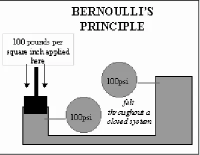
Bernoulli’s Principle (see Figure 1.1) - The total energy in a liquid remains relatively undiminished over distance (M. Mitchell, 2003).
Figure 1.1: Bernoulli’s Principle (Courtesy of the Warfighters Encyclopedia)
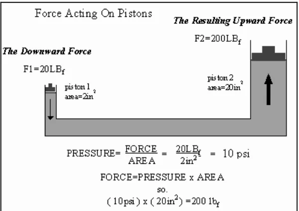
Force = Pressure x Area.
Rearranging the equation algebraically we get:
PRESSURE = FORCE / AREA
In English units, force is measured in pounds force (LBf); pressure is measured in pounds per square inch (PSI), and area is measured in square feet (ft2) or square inches (in2).
Figure 1.2: Figure example on how to calculate the force acting on pistons. (Courtesy of The Warfighter Encyclopedia)
1.4a Basic hydraulic theory
psi. This pressure, acting against the 10 square inch area develops 50 pounds of force.
In a basic hydraulic circuit, the force exerted by a cylinder is dependent upon the cylinder bore size and the pump pressure. (There is no force generated unless there is resistance to the movement of the piston). With 1000 psi pump pressure exerted against a 12 square inch piston area (approximately 4" dia.), a force of 12,000 pounds is developed by the cylinder. The speed at which the piston will move is dependent upon the flow rate (gpm) from the pump and the cylinder area. Hence, if pump delivery is 1 gallon per minute (231 cu.in./min.) the cylinder piston will move at a rate of 20 in.min. (231 cu.in./12 cu.in./min.).
The simplest hydraulic circuit consists of a reservoir, pump, relief valve, 3-way directional control valve, single acting cylinder, connectors and lines. This system is used where the cylinder piston is returned by mechanical force. With the control valve in neutral, pump flow passes through the valve and back to the reservoir. With the valve shifted, oil is directed to the piston side of the cylinder, causing the piston to move, extending the rod. If the valve is returned to neutral, the oil is trapped in the cylinder, holding it in a fixed position, while the pump flow is returned to the reservoir. Shifting the valve in the opposite direction permits the oil to pass through the valve back to the reservoir. The relief valve limits the system pressure to a pre-set amount.
passes through the valve back to the reservoir. Cylinder extend force is a result of the pressure (psi) times the piston area. Retract force is a result of the pressure (psi) times the area difference between the piston minus the rod diameter.
Rotary hydraulic motor circuits are basically the same as cylinder circuits. Systems may be uni-directional or bi-directional. The amount of rotary force (torque) available from the motor is a function of pressure (psi) and motor size. Speed is a function of flow and motor size.
All the systems described above are open center systems due to the oil flowing through the control valve back to tank. Most systems are this type. Closed center systems use control valves with the inlet port blocked and variable displacement pumps. With the control valve in neutral, the pump is “de-stroked” to zero flow.
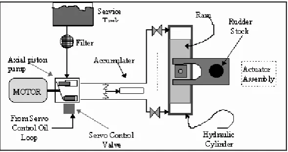
1.4b The Basic Hydraulic Power System
All hydraulic power systems are composed of at least the following basic components (Figure 1.3).
Tank/reservoir/sump - Used to store hydraulic fluid that is not currently in use due to the system’s state or configuration.
Pump - Used to force the hydraulic fluid through the system. Acts as the pressure
source.
Prime mover - The power source for the pump. In hydraulic systems the prime
mover is usually an electric motor.
Valves - Installed to control liquid direction, pressure, and flow rates.
Actuator - Devices that convert the energy of the liquid into mechanical force or
torque. Typically, an actuator is either:
A single piston and cylinder arrangement that results in linear motion. A ship’s steering system uses this design. A series of pistons and cylinders arranged in such a way that they produce rotary motion. Called a hydraulic motor, many of our gun mounts and missile launchers use these pumps to
train the gun or launcher.
Piping - Used to contain and direct hydraulic fluid from one point to another.
1.4c Hydraulic accessories
In addition to the basic hydraulic power system components discussed, hydraulic systems may require additional control components:
Filters/strainers - Used to remove foreign particulate matter from hydraulic fluid
that could damage (by scratching close tolerance components) or clog the system. Pressure regulator - A device that vents off or unloads hydraulic fluid from the high