DESIGN AND DEVELOP A HARMONIC FILTER FOR MAGNETIC BALLAST FLUORESCEN T LAMP
MOHD FAHMI BIN HAMID
BACHELOR OF ELECTRICAL ENGINEERING (POWER ELECTRONIC AND DRIVE)
“I hereby declare that I have read this report and in my opinion this report in term of content and quality requirement fulfils the purpose for the conferring of the Degree of Bachelor in Electrical Engineering.”
Signature : _________________________
Name of Supervisor : MR.MD. HAIRUL NIZAM BIN TALIB
iii
Design and Develop a Harmonic Filter for Magnetic Ballast Fluorescent Lamp
MOHD FAHMI BIN HAMID
This Report Is Submitted In Partial Fulfillment of Requirements for the Degree of Bachelor in Electrical Engineering (Power Electronics & Drive )
Fakulti Ke juruteraan Elektrik Universiti Teknikal Malaysia Melaka
“I hereby declared that this report is a result of my own work except for the excerpts that have been cited clearly in the references.”
Signature : ………
Name : MOHD FAHMI BIN HAMID
v
DEDICATION
Specially dedicated to my beloved family especially my mother
(Fatimah binti Ahmad) and my late father (Allahyarham Hamid bin Puteh); whose very concern, understanding, supporting and patient. Thanks for everything. To All
ACKNOWLEDGEMENTS
Thanks to Allah S.W.T for give me an enthusiasm for completing this PSM 1 smoothly.
Special thanks to the important person, my supervisor, Mr. Md. Hairul Nizam Bin Talib. The person that gave me a lot of advices and guidelines to make sure this project can be performed smoothly and also sharing his idea for completing this project. His constructive criticisms and suggestions make this report a good and quality of report.
I would like to appreciate to my parents and family which always give a motivation and encourage me to become a dean list student. Without their support, it won’t be easy for me to complete the project report.
Also not forget to all the lecturers of Universiti Teknikal Malaysia Melaka (UTeM) especially at Faculty of Electrical Engineering and all of my friends for the motivation and information to me. Thank you for all the help and support that was given. I’m really appreciated it.
v
ABSTRACT
ABSTRAK
vii
TABLE OF CONTEN TS
CHAPTER TITLE PAGE
TITLE PAGE i
ADMISSION ii
DEDICATION iii
ACKNOWLEDGMENT iv
ABSTRACT v
ABSTRAK vi
TABLE OF CONTENTS vii
LIST OF FIGURES xi
LIST OF TABLE xiv
LIST OF APPENDICES xv
LIST OF SYMBOL xvi
I INTRODUCTION AND LITERATUR E REVIEW
1.1 Problem Statements 3
1.2 Project Objective 3
1.4 Thesis Outline 4
1.5 Literature Review 5
1.6 Fluorescent Lamp 6
1.6.1 Fluorescent Fixtures 7 1.6.2 Fluorescent Tube Parts 8 1.6.3 Fluorescent Lamp Operation 8
1.7 Magnetic Ballast 10
1.7.1 Limiting of short circuit current Under fault conditions 10 1.7.2 Limiting of capacitor
Charging current 10 1.7.3 Inductive kick effect 11 1.7.4 Resonant charging effects 11
1.8 Starter of Lamp 12
1.9 Harmonic Distortion 13 1.9.1 Harmonic filter 14
II METHODOLOGY
2.1 Flow chart 17
2.2 OrCAD 19
2.3 Fluke Power Quality Analyzer 21
ix
2.5 Harmonic Filter 26
III RESULT
3.1 Calculation and Simulation 28
3.1.1 Calculation 28
3.1.2 Simulation 30
3.2 Single Tuned Filter 36 3.2.1 Calculation of Single Tuned
Filter 36
3.2.2 Simulation of Single Tuned
Filter 37
3.2.3 Hardware Result 40 3.2.3.1 Measurement Without
Filter 40
3.2.3.2 Measurement With Single Tuned Filter 40 3.2.3.3 Measurement With Single Tuned Filter
And Power Factor Correction 41
IV RESULTS AND DISCUSSION
4.1 Discussion 42
Various Method 42
4.1.1.1 Total Harmonic Distortion Current
Harmonic 42
4.1.1.2 Total Harmonic Distortion Voltage
Harmonic 44
4.1.2 Power Factor 45
V CONCLUSION
5.1 Conclusion 46
5.2 Recommendation 47
LIST OF REFERENCES 49
APPENDICES 50
xi
LIST OF FIGURES
FIGURE TITLE PAGE
1.1 Current and Voltage Waveform For The
Simple Reactor Ballast Circuit 2
1.2 Fluorescent tube part 8
1.3 Fluorescent lamp circuit using magnetic ballast 9
1.4 Exploded view of ballast construction 12
1.5 Starter lamp 13
1.6 Load side waveform 14
1.7 Various type of harmonic filter 15
1.8 Single tuned filter 16
1.9 Double tuned filter 16
2.1 Flow chart of design the harmonic filter
for magnetic ballast construction 17
2.2 Fourier analysis 19
2.3 Total harmonic distortion 20
2.4 Fluke Quality Analyzer 21
2.5 Fundamental and harmonic components 22
2.6 Square wave 24
2.7 Harmonic spectrum 25
3.2 Impedance diagram 29 3.3 Simulation model of the magnetic ballast 30 3.4 Simulation result of output voltage
Waveform for the magnetic ballast
And supply voltage 32
3.5 Simulation result of current output
Waveform for the magnetic ballast 33 3.6 Simulation result of current harmonic
Distortion waveform at the magnetic ballast 34 3.7 Output table result for total harmonic
Distortion at magnetic ballast 34 3.8 Simulation result of voltage harmonic
Distortion waveform at the magnetic ballast 35 3.9 Output table result for total harmonic
Distortion at magnetic ballast 35 3.10 Simulation model of the magnetic ballast
with single tuned filter 37 3.11 Simulation result of current harmonic
with STF 38
3.12 Output table result for total harmonic
distortion current harmonic after adding STF 38 3.13 Simulation result of voltage harmonic
with STF 39
3.14 Output table result for total harmonic
xiii 3.15 (i) Current harmonic without filter,
(ii) Voltage harmonic without filter and
(iii) Power factor without filter 40 3.16 (i) Current harmonic with single tuned filter,
(ii) Voltage harmonic with single tuned filter and (iii) Power factor with single tuned filter 40 3.17 (i) Current harmonic with single tuned filter
and power factor correction, (ii) Voltage harmonic with single tuned filter and power factor correction and (iii) Power factor with single tuned filter with power factor correction 41 3.18 Single tuned filter is being tested 41 5.1 Single tuned filter for 3rd, 5th and 7th 48
5.2 Basic scheme of the system with the
parallel active filter 49
LIST OF TABLE
FIGURE TITLE PAGE
3.1 Measurement Result 28
4.1 Comparison of Current Harmonic Distortion
Between Calculation, Simulation and Measurement 42 4.2 Comparison of Voltage Harmonic Distortion
Between Calculation, Simulation and Measurement 44
xv
LIST OF APPENDICES
APPENDIX TITLE PAGE
A Project Planning 51
B Datasheet of the Lamp 53
C Result Measurement 54
LIST OF SYMBOL
2
CHAPTER I
INTRODUCTION AND LITERATUR E REVIEW
1.1 Introduction
The definition of visible lights is wavelengths of electromagnetic radiation that can be seen with the human eye. Isaac Newton proposes that light existed as “CORPUSCLES”. The discovery of electric power and the possibility of transmitting it in a simple manner facilitated the development of modern lamps. There are various types of lamps being manufactured which can divide into six categories: incandescent, fluorescent, high-pressure sodium (HPS), low-high-pressure sodium (LPS), mercury vapor and metal halide. The fluorescent lamp is the most familiar of the large class of lamps referred to as discharge lamps. In these lamps light is creating by an electrical discharge within gas or vapor.
When a fluorescent lamp in its running condition, there is an arc discharge along the length of the tube and the mercury vapor ionizes. The combination of the ionization itself and the excitation of the mercury atoms produce electromagnetic radiation. The major characteristics to be considered when choosing a lamp are its luminous efficacy, life, lumen depreciation and color rendering. Luminous efficacy is the measure of the lamp’s ability to convert input electric power, in watts, into output luminous flux, in lumens, and is measured in lumens per watt (lm/w). The luminous flux of a light source is the electromagnetic radiation within the visible part of the electromagnetic spectrum multiplied by the sensitivity of man’s eyes to that part of the light from the source.
regulation in the sense that changes in supply voltage should not be reflected in corresponding large changes in light output.
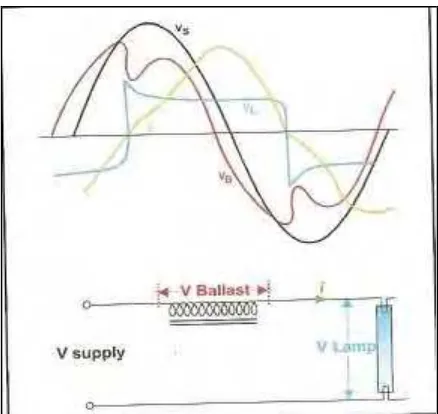
Figure 1.1: Current and voltage waveform for the simple reactor ballast circuit.
From figure 1.1 that simple reactor ballast provides a lamp voltage that is out of phase with the current. This is helpful as it ensure sufficient voltage for restrike at each half cycle. A resistive ballast would not only be wasteful, but would result in a significant discontinuity as the supply voltage change direction resulting in worse harmonic generation.
Harmonic distortion is voltage and current frequency riding top of the normal sinusoidal voltage and current waveform. It can be found in voltage and current waveform. Current distortion generated by non-linear loads. It creates voltage distortion according to ohm’s law. Current distortion will affect power system and distribution equipment while voltage distortion will affect all load connect to particular bus or phase. Current distortion will directly or indirectly destruction of load loss of product.
Direct perspective for current distortion:
Transformer will overheat and fail even through it not use fully load
4
Indirectly perspective for current distortion: Create resonant
May excite resonant frequency in the system
Resonant may cause extremely high harmonic voltage and also possibly damaging the equipment
1.2 Proble m statements
Most of the magnetic ballast fluorescent lamp in the market had not provided power factor correction and harmonic filter. From the previous studies, a magnetic ballast of fluorescent lamp can produce 18-35% of harmonic distortion. A house can produce more than 35% of harmonic distortion depending on the number of fluorescent lamps installed. The problem cause by the harmonic is poor power factor and it can also damage the entire component of the fluorescent lamp in long term. Besides that, the lower value of power factor due to harmonic means the larger current will be drawn from the utility which will increase the power consumption. This means the electricity bill will be higher. Moreover, the existing harmonic filters in the market are only available for industrial use and they are expensive.
1.3 Project objectives
These are the objectives of this project:
1. To design and develop harmonic filter to get an improvement in term of power quality (harmonic) for a fluorescent lamp
2. To simulate and analyze the performance of magnetic ballast model (Newton ballast 32W for fluorescent lamp) based on design, power efficiency and harmonic filter.
1.4 Project scopes
The scope of this project is to analyze the harmonic produce in the model (Newton ballast 32W for fluorescent lamp). After analyze the model, a design of harmonic filter will be produce to reduce the available harmonic components. The targets of harmonic component are 3rd, 5th and 7th. The harmonic filter design will use passive component as
the based component in order to reduce the targeted harmonic components. A comparison between with and without harmonic filter will be analyze.
1.5 Thesis outline
The purpose of this project is to design a harmonic filter for 32W magnetic ballast fluorescent lamp. It will discuss in detail in five sections. It is introduction, literature review, methodology, results and discussions, and conclusion.
In chapter one (introduction and literature review), it discussed about the major characteristics to be considered when choosing a lamp. It also discuss about the magnetic ballast and harmonic filter as well. The problem statement, project objectives, scope and thesis outline are also included in this chapter. This chapter also discuss about the operation of fluorescent lamp, component in fluorescent lamp and harmonic distortion. Furthermore, it will discuss about harmonic filter that has being produce from previous studies.
In chapter two (methodology), it discussed about the techniques and consideration that applied during PSM1. In simulation part, OrCAD software is used to simulate the design circuit before it can proceed to the hardware part. The Fluke meter is used to do the analysis of the circuit operation of magnetic ballast. The calculation using Fourier analysis is done to determine the required filter.
6 Analysis on harmonic distortion also included. The measurement result from the laboratory is also show in this chapter.
In chapter four (discussions of result), all the measurement result will be compared in this chapter. An analysis will be performing to prove the calculation and measurement result according to expectation.
In chapter five (conclusion), brief summaries of this project are provided. Besides that, it also includes a recommendation of this project.
1.6 Lite rature Review
The article in [1] defined that fluorescent lamps are important and widely used in our places. The current waveforms of fluorescent lamps are non-sinusoidal because of luminous discharge mechanism. This article also stated that every fluorescent lamp was different value in producing harmonic current even the same type of lamp. The article added that if only the current waveform of every single device has been pre measured, the different harmonic source will becomes unpredictable. However, it is impossible to use this kind of method.
The article in [2] informs that, the 4 feet magnetic ballast fluorescent lamp is the most common lighting fixture Malaysia resident. The main reason is because it produces the highest lumens compare to other incandescent bulb and compact fluorescent lamp (CFL). From article [1] added that A CFL only produces up to 1600 lumen depending on the power of the CFL .A fluorescent tube can produces 3200 lumens. The fluorescent lamp is not an energy efficient lamp because the magnetic ballast commonly used in it.
Article in [3] extended that fluorescent lamp also have several disadvantages. First, it must be properly disposed so that the mercury not going into the environment. The lamp life can be reduces by turning the lamps on and off. The process is called sputtering. The process occurs when reduction is cause from the mercury ions that collide with the electron that being release by the electrode.
The article also stated physically, compare to the warm incandescent lamp the fluorescent lamps color sometimes is cooler and less pleasing. Although, this issues is already solved by designing a new model that generate higher harmonics the ballast in fluorescent. The Lamps with higher harmonic distortions will reduce the light power intensity. So the lamp will flickering, and will give problems to other devices that connected to the electrical network. Furthermore, additional lamps that installed in a building, bigger harmonic will generate because of the total building load.
1.7 Fluorescent Lamp
The fluorescent lamp was the most advance technology to be a commercial success in small scale lighting since the tungsten incandescent bulb. Its greatly increased efficiency resulted in cool (temperature wise) brightly lit workplaces (offices and factories) as well as home kitchens and baths. Fluorescent lamps are a type of gas discharge tube similar to neon signs and mercury or sodium vapor street or yard lights. A pair of electrodes, one at each end - are sealed along with a drop of mercury and some inert gases (usually argon) at very low pressure inside a glass tube. The inside of the tube is coated with a phosphor which produces visible light when excited with ultra-violet (UV) radiation. The electrodes are in the form of filaments which for preheat and rapid or warm start fixtures are heated during the starting process to decrease the voltage requirements and remain hot during normal operation as a result of the gas discharge.