Analysis of Tool Performance during Ball-end Milling of Aluminium
Alloy 6061-T6
M.S. Kasim
1,a, M.H. Atan
2,b, C.H. Che Haron
3,c, J.A. Ghani
3,d,
M.A Sulaiman
1,e, E Mohamad
1,f, M. Minhat
1,g, M. Hadzley
1,hand J.B. Saedon
4,i1Faculty of Manufacturing Engineering, Universiti Teknikal Malaysia Melaka, 76100 Hang Tuah
Jaya, Melaka, Malaysia
2Politeknik Merlimau, 77300 Merlimau, Melaka, Malaysia
3Faculty of Engineering and Built Environment, Universiti Kebangsaan Malaysia, 43600 Bangi,
Selangor, Malaysia
4Faculty of Mechanical Engineering, Universiti Teknologi MARA, Malaysia
a[email protected], b[email protected], c[email protected],
d[email protected], e[email protected], f[email protected],
g[email protected], h[email protected], i[email protected]
Key words: High speed machining, Aluminium alloy 6061-T6, Dry machining, Tool wear, Wear mechanism, Ball-end milling
Abstract. This article presents the tool wear mechanism when machining Aluminium alloy 6061-T6 with PVD coated carbide under dry cutting condition. Cutting parameters selected were cutting speed, Vc = 115-145 m/min; feed rate fz = 0.15-0.2 mm/tooth and depth of cut, ap = 0.5-0.75 mm. The result showed the tool life of PVD TiAlN ranged from 11 to 97 min. Full factorial approach was employed to exhibit relationship between parameter input and output. From the analysis, cutting speed was found to be the most significant factor for tool performance followed by feed rate and depth of cut. It was also found that most of failure modes occurred were notch wear and flaking near those found near depth of cut line.
Introduction
Aluminium alloy 6061 is a precipitation hardening Aluminium alloy that consists of silicon and magnesium as major alloying elements. It has been applied extensively in plastic industry due to good mechanical properties. The material possesses superior properties that resist high load and corrosion.
The cost of replacing cutting tool is 3% of production cost [1]. Manufacturer has put efforts on research as to improve life span of cutting tool. Degradation of tool performance not only increase production cost but also affect quality of machined part [2]. It is therefore many researchers to study the appropriate cutting condition so that cutting tool can be prolonged. Studies from previous literatures found that the tool performance of carbide cutter in milling of Aluminium alloy less satisfactory, tool wear rate was too high and has very short tool life [3]. Chern et al., 2006 has studied relationship between cutter type and burr formation during face mill [4]. Several quality issues related with Aluminium has been investigated by Amran et al., 2013. There were correlation between cutting speed and feed rate on surface finish [5]. Chen et al., 2005 proved that modification on ball-end cutting tool capable to improve feed rate and increase productivity [6].
Industries are forced to seriously evaluate their design and manufacturing of their products due to the competition in the marketplace, especially when the shape of product is intricate and complex. Selection of ball end milling tool to make the process is one of the most appropriate processes due to its smooth cutting tip geometry which can reduce the stress concentration. However, the complex shape of round nose geometry exhibit tool wear mode that different than the flat end milling tool [7,8].
The objective of this paper is primarily to investigate the effect of cutting parameter on cutting tool performance. Width of flank wear is used to assess the limits of tool life under various cutting conditions. Second objective is to identify the optimized combination of cutting parameter that will result in the longest tool life.
Methodology
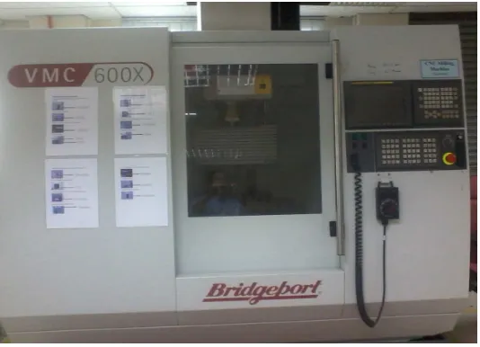
The work piece material used for this experiment was Aluminium Alloy 6061. The chemical compositions of this material include 17 wt. % Fe, 0.63 wt. % Si, 0.52 wt. % Mn, 0.02 wt. % Ti, 0.32 wt. % Cu and Al (balance). The dimension of the block was squared into final size of 200 × 200 × 40 mm. The machined block surface underwent a face milling of 0.5 mm to remove any surface irregularities and residual stress resulting from the production. The selected cutting tools were Sumitomo QPMT 10T335PPEN, a fine grain of tungsten carbide (10 wt. % Co) coated with physical vapour deposition (PVD) of TiAlN. The 10 mm dia. insert was attached to the tool holder with a 16 mm nominal diameter, a rake angle of -3°, a radial rake angle of 0° and relief angle of 11°. The cutting experiments were carried out on a CNC VMC600X milling machine with a maximum spindle speed of 5000 revolutions/min (Fig. 1). Three cutting parameter was selected, namely; cutting speed, Vc (115 – 145 m/min); feed rate, fz (0.15 - 0.2 mm/tooth); depth of cut, ap (0.5 – 0.75 mm).
Full factorial was used to design experiment to determine the influent of cutting parameter on tool wear. Considering three variable input with two levels, the total experiments are 8 runs (23). All
experiments were done under the dry and finishing condition. Flank wear was analysed using a two-axis toolmaker’s microscope for flank wear measurement. The test will be stopped when the flank wear, VB reaches 0.3 mm. Worn out tools were further examined microscopic image of tool wear
using a scanning electron microscope (SEM) JEOL JSM-638OLA.
Fig. 1 CNC Milling VMC600X.
Result and discussion
Table 1 Cutting condition and experiment results.
In order to analyse the influence of cutting parameter on response (tool life), analysis of variance (ANOVA) was performed. All the P-value for all factors found to be less than 5% confident interval. The F-Value for cutting speed of 157609, followed by feed rate of 144146 and depth of cut of 134200. The F-value indicates the tool life dominantly controlled by cutting speed.
Fig. 2 shows the relationship between cutting parameters (cutting speed, feed rate and depth of cut) and tool life. It consistence with theory with an increase in the cutting speed, the tool life is shorten to a minimum. It was similarly occurred to feed rate and depth of cut. The steep angle of the graph plane shows the most significant of each factor contribute to tool life. It was agreed with F-value from ANOVA that cutting speed was found to be most significant followed by feed rate and depth of cut. The maximum tool life (97 min) can be achieved by the combination of Vc = 115 m / min, fz = 0:15 mm / tooth and ap = 0.5 mm.
(a) (b)
Fig. 2 Influence of cutting parameter on flank wear, Vb when milling Aluminium 6061 – T6 with PVD tools; (a) cutting speed against feed rate (b) feed rate against depth of cut.
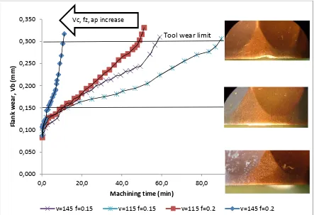
Fig. 3shows the progress of flank wear thorough machining time. The tool wear pattern observed is typical which accelerate at initial stage, retain constant at steady stage and accelerate back at the end of tool life. The trend shows the total machining time decreased as Vc, fz and ap are increased.
Fig. 3 Tool wear plot in terms of machining time at ap = 0.75 mm.
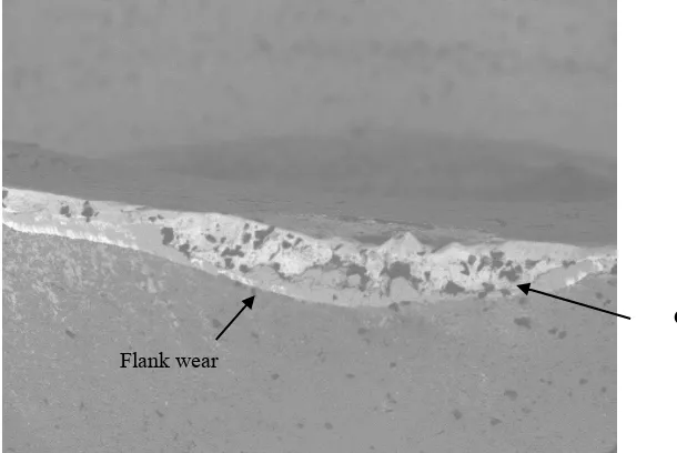
Based on the experiment, it was identified that notch wear and flank wear are the major wear mode during end milling. Notch wear formation as an arc shape normally found at a depth of cut line (Fig. 4). It was incorporated with higher volume of underformed chips to be removed at that region. On the machined surface, the deformation of grain boundary from previous cut causes a hardening effect that worsening the notch wear. Moreover, the interrupted cutting condition of milling process degrade bonding between TiAlN coating and WC substrate, thus cracking and flaking can be found on the rake face due to this cyclic load.
Fig. 4 The main tool failure mode during end milling of Aluminium 6061.
Due to the geometry of the ball nose cutting tool is complex, the effective cutting speed, Vceff is
changed at every depth of the cutting tool (Fig. 5). The effective cutting speed increases as the location close to the depth of cut line. It relates to the cutter radius that varied from the tool tip to depth of cut line. Fig. 6 shows the flank wear occurred on the cutting edge. The formation of flank wear is linearly, not uniform identified along cutting edge. The maximum flank wear was found at a
0,000
v=145 f=0.15 v=115 f=0.15 v=115 f=0.2 v=145 f=0.2
Vc, fz, ap increase
Tool wear limit
Flaking
depth of cut zone as a conjunction with the maximum effective cutting speed. Therefore the abrasive wear occurred aggressively in this region. This was likely the maximum temperature generated at the vicinity of depth of cut line due to the maximum volume of material deformation and abrasion. The high temperature is then softening cutting tool. Cracking on cutting edge accelerates tool failure catastrophically.
Fig. 5 Effective cutting speed, Vceff at different tool depth.
Fig. 6 SEM image of flank wear on cutting edge with the magnification of 140 X at Vc = 145 m/min, fz = 0.15 mm/tooth, ap = 0.75 mm.
Maximum effective cutting speed
Minimum effective cutting speed
Flank wear
Tool tip
Depth of cut line
Conclusion
In the studies milling of Aluminium alloy using TiAlN coating carbide, the following conclusions can be rendered:
1. Tool performance of coated carbide cutting tools in dry milling Aluminium alloy 6061 is between 11 minutes to 97 minutes.
2. The cutting speed is a key factor in influencing the life of carbide cutting where it carries a greater effect in reducing the cutting tool life, followed by feed rate and depth of cut.
3. Maximum life of 97 minutes can be achieved by coated carbide cutting tools with the optimal cutting conditions: Vc = 115 m / min, fz = 0:15 mm / tooth and ap = 0.5 mm.
4. The primary tool failures during experiment were notch wear and flank wear. Flaking and cracking of the coating is worn another types of failure mode that are also found during cutting process. Under microscopic view, abrasion is primary wear mechanism that has contributed to significant flank wear on the tool flank face.
Acknowledgement. The authors wish to thank Universiti Teknikal Malaysia Melaka, Universiti Kebangsaan Malaysia, Politeknik Merlimau and the Government of Malaysia for technical and financial support for the experiment and conference (Project No. UKM-GUP-BTT-07-25-171 and PJP/2013/FKP(18A)/S01276).
References
[1] Information on http://www.moldmakingtechnology.com/articles/the-real-cost-of-your-cutting-tools
[2] A. Ginting, M. Nouari, Surface integrity of dry machined titanium alloys, Int. J. Mach. Tools Manuf. 49 (2009) 325-332.
[3] E.G. Ng, D. Szablewski, M. Dumitrescu, M.A. Elbestawi, J.H. Sokolowski, High speed face milling of aluminium silicon alloy casting, CIRP Annals – Manuf. Technol. 53 (2004) 69-72.
[4] G.-L. Chern, Experimental observation and analysis of burr formation mechanisms in face milling of aluminum alloys, Int. J. Mach. Tools Manuf. 46 (2006) 1517-1525.
[5] M.A. Amran, S. Salmah, N.I.S. Hussein, R. Izamshah, M. Hadzley, S. Sivarao, M.S. Kasim, M.A. Sulaiman, Effects of machine parameters on surface roughness using response surface method in drilling process, Procedia Eng. 68 (2013) 24-29.
[6] J.-S. Chen, Y.-K. Huang, M.-S. Chen, Feedrate Optimization and Tool Profile Modification for the High-Efficiency Ball-End Milling Process, Int. J. Mach. Tools Manuf. 45 (2005) 1070-1076. [7] E.O. Ezugwu, Z.M. Wang, A.R. Machado, The machinability of nickel-based alloys: A review, J. Mat. Process. Technol. 86 (1999) 1-16.
Analysis of Tool Performance during Ball-End Milling of Aluminium Alloy 6061-T6
10.4028/www.scientific.net/AMM.761.318
DOI References
[2] A. Ginting, M. Nouari, Surface integrity of dry machined titanium alloys, Int. J. Mach. Tools Manuf. 49 (2009) 325-332.
http://dx.doi.org/10.1016/j.ijmachtools.2008.10.011
[3] E.G. Ng, D. Szablewski, M. Dumitrescu, M.A. Elbestawi, J.H. Sokolowski, High speed face milling of aluminium silicon alloy casting, CIRP Annals - Manuf. Technol. 53 (2004) 69-72.
http://dx.doi.org/10.1016/S0007-8506(07)60647-7
[4] G. -L. Chern, Experimental observation and analysis of burr formation mechanisms in face milling of aluminum alloys, Int. J. Mach. Tools Manuf. 46 (2006) 1517-1525.
http://dx.doi.org/10.1016/j.ijmachtools.2005.09.006
[5] M.A. Amran, S. Salmah, N.I.S. Hussein, R. Izamshah, M. Hadzley, S. Sivarao, M.S. Kasim, M.A. Sulaiman, Effects of machine parameters on surface roughness using response surface method in drilling process, Procedia Eng. 68 (2013) 24-29.
http://dx.doi.org/10.1016/j.proeng.2013.12.142
[6] J. -S. Chen, Y. -K. Huang, M. -S. Chen, Feedrate Optimization and Tool Profile Modification for the High-Efficiency Ball-End Milling Process, Int. J. Mach. Tools Manuf. 45 (2005) 1070-1076.
http://dx.doi.org/10.1016/j.ijmachtools.2004.11.020
[7] E.O. Ezugwu, Z.M. Wang, A.R. Machado, The machinability of nickel-based alloys: A review, J. Mat. Process. Technol. 86 (1999) 1-16.
http://dx.doi.org/10.1016/S0924-0136(98)00314-8
[8] J. -S. Chen, Y. -K. Huang, M. -S. Chen, A study of the surface scallop generating mechanism in the ball-end milling process, Int. J. Mach. Tools Manuf. 45 (2005) 1077-1084.