DEVELOPMENT OF CONTROLLER FOR WIRELESS ROBOTICS HAND IN HAZARDOUS ENVIRONMENT
KHOO HUI YEE
A report submitted in partial fulfillment of the requirement for the degree of
Bachelor of Mechatronics Engineering
Faculty of Electrical Engineering
UNIVERSITI TEKNIKAL MALAYSIA MELAKA
“I hereby declare that I have read through this report entitle “Development of Controller for Wireless Robotics Hand In Hazardous Environment” and found that it has comply the partial fulfillment for awarding the degree of Bachelor of Mechatronics Engineering”
Signature :……….
I declare that this report entitle “Development of Controller for Wireless Robotics Hand in Hazardous Environment” is the result of my own research except as cited in the references. The report has not been accepted for any degree and is not concurrently submitted in candidature of any other degree.
Signature :………. Name : Khoo Hui Yee
ACKNOWLEDGEMENT
As an introduction for this section, I’m feeling honoured because I am able to accomplish this report that was given as my responsibility in order to partially fulfil a part of condition to be awarded Bachelor of Mechatronics Engineering. I’m very honoured and happy on the explanation, teaching and knowledge that didn’t even cross my mind before. To be precise, I would like to thank every party that provided me the possibility to complete this project and report.
I would like to thank and show my gratitude to my final year project supervisor, Dr. Mariam Binti Md Ghazaly and Engr. Mohd Rusdy Bin Yaacob who assisted me in handling the necessary paperwork and providing suggestions in order for me to undergo project smoothly.
ABSTRACT
ABSTRAK
TABLE OF CONTENT
CHAPTER TITLE PAGE
ACKNOWLEDGEMENT i
ABSTRACT ii
TABLE OF CONTENT iv
LIST OF TABLES vii
LIST OF FIGURES x
LIST OF ABBREVIATIONS xiii
LIST OF APPENDICES xiv
1 INTRODUCTION
1.1 Motivation 1
1.2 Problem Statement 2
1.3 Objectives 3
1.4 Project Scope 3
1.5 Chapter Overview 4
2 LITERATURE REVIEW
2.1 Introduction 5
2.2 Types of Actuator 5
2.2.1 Servo Motor 5
2.2.2 Pneumatics Actuator 6
2.2.3 DC Geared Motor 7
2.2.4 Conclusion 8
2.3 Types of Sensor 9
2.3.1 Flex Sensor 9
2.3.2 Pneumatics Force Feedback 9
2.3.3.Tactile Sensor 10
CHAPTER TITLE PAGE
2.4 Types of Controller 11
2.4.1 PID Controller 12
2.4.2 Fuzzy PID Controller 13
2.4.3 PD Controller 14
2.4.4 Conclusion 16
2.5 Control System 17
2.5.1 Closed-loop Control System 17 2.5.2 Open-loop Control System 19
2.5.3 Conclusion 19
2.6 MATLAB tools 20
2.6.1 e_Grasp 20
2.6.2 Simulink 21
2.6.3 SynGrasp 22
2.6.4 Conclusion 24
3 METHODOLOGY
3.1 Introduction 25
3.2 Project Planning 25
3.2.1 Gantt Chart 27
3.2.2 Milestone 28
3.3 Development Process 28
3.3.1 Electrical System 31
3.3.1.1 Xbee Module 31
3.3.1.2 Servo Motor 33
3.3.1.3 DC Geared Motor 35
3.3.1.4 Flex Sensor 37
3.3.1.5 Micro-Box 2000/2000C 38 3.3.1.5.1 Micro-Box Connector Descriptions 39
3.3.2 Mechanical System 42
3.4 Experiments Setup 46
CHAPTER TITLE PAGE 3.4.2 Robotics Hand Equipment Setup And Procedures 49 3.4.2.1 Open Loop System 49 3.4.2.2 Closed Loop System 53 3.4.3 PID Controller Block Diagram 54
4 RESULT AND ANALYSIS
4.1 Introduction 56
4.2 Flex Sensor Equipment Setup And Procedures 56 4.3 Robotics Hand Equipment Setup And Procedures 88
4.3.1 Open Loop System 88
4.3.2 Closed Loop System 89
4.4 PID Controller Block Diagram 92
5 CONCLUSION AND RECOMMENDATION
5.1 Conclusion 99
5.2 Recommendation 100
REFERENCES 101
LIST OF TABLES
TABLE TITLE PAGE
2.1 Function and description for hand modeling [19] 23 2.2 Function and description for grasp definition [19] 23 2.3 Function and description for grasp analysis [19] 23 2.4 Function and description for graphics [19] 24
3.1 Activities planned 28
3.2 Components used in data glove and robotics hand 31 3.3 Specification of Xbee series 1 module 32
3.4 Configuration of Xbee module 33
3.5 Specification of TGY-90S micro servo 34 3.6 Pin descriptions for each of the connector of motor 37 3.7 Standard resistance value of flex sensor for different bending
angle
38
3.8 Descriptions for each of the connector 1 40 3.9 Descriptions for each of the connector 2 41 3.10 Descriptions for each of the connector 3 42 3.11 General specification of the base 45
4.1 Output voltage for 0.5V 58
4.2 Output voltage for 1.0V 58
4.3 Output voltage for 1.5V 59
4.4 Output voltage for 2.0V 59
4.5 Output voltage for 2.5V 60
4.6 Output voltage for 3.0V 60
4.7 Output voltage for 3.5V 61
4.8 Output voltage for 4.0V 61
4.9 Output voltage for 4.5V 62
4.10 Output voltage for 5.0V 62
TABLE TITLE PAGE
4.12 Output voltage for 1.0V 64
4.13 Output voltage for 1.5V 65
4.14 Output voltage for 2.0V 65
4.15 Output voltage for 2.5V 66
4.16 Output voltage for 3.0V 66
4.17 Output voltage for 3.5V 67
4.18 Output voltage for 4.0V 67
4.19 Output voltage for 4.5V 68
4.20 Output voltage for 5.0V 68
4.21 Output voltage for 0.5V 70
4.22 Output voltage for 1.0V 70
4.23 Output voltage for 1.5V 71
4.24 Output voltage for 2.0V 71
4.25 Output voltage for 2.5V 72
4.26 Output voltage for 3.0V 72
4.27 Output voltage for 3.5V 73
4.28 Output voltage for 4.0V 73
4.29 Output voltage for 4.5V 74
4.30 Output voltage for 5.0V 74
4.31 Output voltage for 0.5V 76
4.32 Output voltage for 1.0V 76
4.33 Output voltage for 1.5V 77
4.34 Output voltage for 2.0V 77
4.35 Output voltage for 2.5V 78
4.36 Output voltage for 3.0V 78
4.37 Output voltage for 3.5V 79
4.38 Output voltage for 4.0V 79
4.39 Output voltage for 4.5V 80
4.40 Output voltage for 5.0V 80
4.41 Output voltage for 0.5V 82
4.42 Output voltage for 1.0V 82
TABLE TITLE PAGE
4.44 Output voltage for 2.0V 83
4.45 Output voltage for 2.5V 84
4.46 Output voltage for 3.0V 84
4.47 Output voltage for 3.5V 85
4.48 Output voltage for 4.0V 85
4.49 Output voltage for 4.5V 86
4.50 Output voltage for 5.0V 86
LIST OF FIGURES
FIGURE TITLE PAGE
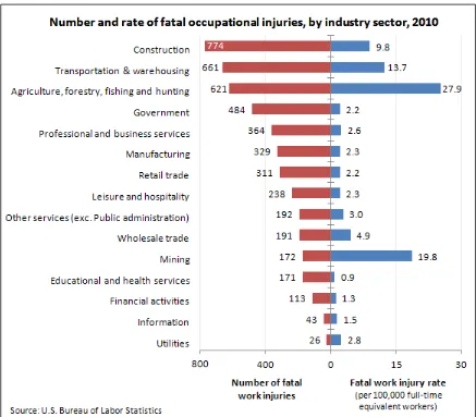
1.1 Number and rate of fatal occupational injuries by industry sector in 2010 2 2.1 Relationship between the motor rotational speed/torque to joint of
speed/torque [1] 6
2.2 Schematic diagram of pneumatics actuator [2] 7 2.3 Schematic diagram of pneumatics actuator with robot finger [2] 7
2.4 DC geared motor 8
2.5 Prototype of pneumatics force feedback data glove [6] 10
2.6 Fabric tactile sensor [7] 11
2.7 Block Diagram of the PID control system with gap [3] 12
2.8 Response of staircase signal [3] 12
2.9 Block diagram of self-tuning fuzzy PID controller [1] 13 2.10 Result of metacarpophalangeal joint (MP) tracking with conventional PID
and fuzzy PID controller [1]
14
2.11 Result of thumb carpometacarpal joint (CM) tracking with conventional PID and fuzzy PID controller [1]
14
2.12 Result for the control in the joint space (a) finger joint trajectories; (b) joint position error; (c) cable tension related to joint torque; (d) tip motion in the Cartesian space [4]
15
2.13 Result for the control in the slider space (a) finger joint trajectories; (b) slider position error; (c) cable tension related to joint torque; (d) tip motion in the Cartesian space [4]
16
2.14 Output curves of the open loop control system and PID closed loop control system [5]
17
FIGURE TITLE PAGE
2.19 Linkage with MATLAB AI tools [8] 21
2.20 Block diagram forms by Simulink [11] 22
3.1 Project flow chart 26
3.2 Gantt chart for FYP 1 and FYP 2 27
3.3 Flex sensor mounted on master data glove 29
3.4 System flow chart 30
3.5 Master data glove 31
3.6 Xbee Explorer USB 32
3.7 Micro servo attached at robotics hand 33
3.8 Dimension of TGY-90S micro servo 34
3.9 Micro servo after adding 2.2kΩ resistor 35
3.10 Comparison between three motor 36
3.11 Connector of pin descriptions 37
3.12 Bending angle of flex sensor 38
3.13 Micro-box 2000/2000C 39
3.14 Connector 1 39
3.15 Connector 2 40
3.16 Connector 3 41
3.17 Base assemble 43
3.18 Base for robotics hand 43
3.19 Holder (left) 44
3.20 Holder (right) 44
3.21 Gripper (left) 44
3.22 Gripper (right) 44
3.23 Experiment setup for robotics hand (top view) 46 3.24 Experiment setup for robotics hand (side view) 46
3.25 Experiment setup 47
3.26 Output voltage state in Arduino serial monitor 48
3.27 Robotics finger with label 49
3.28 4 pins DIN female connector 50
3.29 6 pins DIN female connector 50
FIGURE TITLE PAGE 3.31 Block diagram for Random White Noise 51
3.32 System identification tool 52
LIST OF ABBREVIATIONS
mW - Milliwatt
dBm - Decibel-milli
ft - Feet
m - Metre
Kbps - Kilobit per second
GHz - Gigahertz
sec - Second in Time
V - Volt
kg-cm - Kilogram centimeters
° - Degree
θ - Angle
Ω - Ohm
LIST OF APPENDICES
APPENDIX TITLE PAGE
A Arduino coding to read the output voltage of flex sensor 103 B Dimension of base, holder (left), holder (right), gripper (left) and
CHAPTER 1
INTRODUCTION
This section will explain about the project background/motivation, problem statement, objectives and scope of this project.
1.1 Motivation
Robotics hand is the machine mechanisms that can mimic the motion of human hand. In general, robotics hand plays an important role in the application that requires precision and dexterity. It is very useful to handle the work that unreachable or dangerous to human such as in industry sector and high chemical area.
Figure 1.1: Number and rate of fatal occupational injuries by industry sector in 2010
1.2 Problem statement
performance of the robotics hand need to be analyze and the accurateness of the robotics hand need to be compared with actual human hand so that it obtain the accuracy grasp.
1.3 Objectives
The objectives of the project are:
1) To design and develop a controller for improving the system performance of wireless robotics hand.
2) To simulate the performance of DC geared motor and flex sensor using MATLAB software.
3) To analyze the system performance of the wireless robotics hand with a controller.
1.4 Project scope
1.5 Chapter Overview
For Chapter 1, it explain about the motivation, problem statement, objectives and scope of the project. Motivation of this project is because of there are many injured cases in the hazardous environment such as in industrial area. The problem statement for this project is that the hardware is done by previous student but it is in open loop system. Due to this problem, micro servo that currently used must be change to DC geared motor with encoder.
In Chapter 2, a review research project on the important elements in development the software and hardware of robotics hand. The first research study is focuses on hardware such as types of motor and robotics hand. Second research study is discusses the types on controller and its system either open loop system or closed loop system. Third research is discusses the MATLAB tools used to analyze the performance of robotics hand.
The list of procedure or analysis methods will be describe in Chapter 3. In this chapter, there consists of system flow chart, development process and experiment conducted. There also describe about theoretical analysis of the method that applies to this project. There are three experiments which is experiment setup and procedures of flex sensor, experiment setup and procedures of robotics hand and PID controller block diagram.
All the results obtained for three experiment will be shown Chapter 4. The results from flex sensor, robotics hand and controller shown is measured and simulated follow the procedure in Chapter 3. Results obtained is tabulated into table and graph is plotted. Based on the results obtained, the performance of flex sensor, performance of DC geared motor and performance of controller is analyzed and discussed.
CHAPTER 2
LITERATURE REVIEW
2.1 Introduction
In this section, a review of previous research project on the important elements in development the software and hardware of wireless robotics hand. The first research study is focuses on hardware such as types of motor and robotics hand. Second research study is discusses the types on controller and its system either open loop system or closed loop system. The third research is discusses the MATLAB tools used to analyze the robotics hand in term of grasping object.
2.2 Types of actuator
Selection of the actuator that used to drive the robotics hand need to be considering some parameter such as efficiency, torque and size of the motor. This section will discuss the types of actuator that commonly used on robotics hand which is servo motor, pneumatics actuator and DC geared motor.
2.2.1 Servo motor
and it will show no overshoot occur. Figure 2.1 shows the relationship between finger joint with the servo driver. In the region of ‘moving’, the graph shows that the output of joint is more faster than the input of the motor speed but the output torque is smaller than torque for the input.
Figure 2.1: Relationship between the motor rotational speed/torque to joint of speed/torque [1]