248
HALF CAR ACTIVE SUSPENSION SYSTEM
Amat A. Basari1,a*, Saifullah Salam2,b Khairul A.A. Aziz3,c and Redzuan A. Manap4,d
1,2,3,4 Universiti Teknikal Malaysia Melaka, Durian Tunggal, Malaysia. a
Email: amat@utem.edu.my, bEmail: saifullah@utem.edu.my, cEmail: khairulazha@utem.edu.my, dEmail: redzuan@utem.edu.my
Abstract— This paper presents a new method in modeling an active suspension system for a half-car model in state space form and develop a robust control strategy in controlling the active suspension system. Fuzzy logic is used to control the system. Velocity and displacement of front wheels are taken as input variables of the fuzzy logic controller. Active forces improving vehicle driving, ride comfort and handling properties are considered to be the controller outputs. The controller design is proposed to minimize chassis and wheels deflection when uneven road surfaces, pavement points, etc. are acting on the tires of running cars. Comparison of performance of active suspension fuzzy control system with passive suspension system is shown using Matlab/Simulink simulation. From the result, it shows that active suspension system has better performance than the passive suspension system.
KeywordsüHalf Car Suspension System, Fuzzy Logic
Controller, Active Suspension System, Passive Suspension System
O. INTRODUCTION
Suspension system of a vehicle is critical in many aspects. Its main function is to isolate the body of the vehicle from the road surface. Besides that, it also determines the vehicle handling performance as well as the comfortness. Typical design of suspension system will consist of shock absorber and coil spring that will minimize the shock absorbsion by passenger of the vehicle. In order to obtain a good response, we may vary the constant value of each element stated above. Over pass decades, many researchers have come with an idea of active suspension system. The idea is that, we may add another control element to the system. By adding the third control element to the system, we can create a closed loop system as the input from reflection of the tire will feedback to the system.
There are many works have been done in designing an active suspension system. The dynamic of suspension system is nonlinear. Therefore, the use of robust controller in the system is needed. Uncertainty from road surface is another factor that contributes to the need of a robust control scheme for the system. [1] and [2] have obtained a good performance of the active system by utilizing the PI sliding mode control and nonlinear optimal control scheme. Both papers present the effectiveness of the control scheme in giving better performance of the system. Application of fuzzy logic controller in the active suspension system is presented by many researchers. In [3], the writer has proposed the
fuzzy control for a quarter car suspension system using the mamdani model approach. While in [4], the writer has work on the Takagi-Sugeno model. The ability of fuzzy control in controlling a nonlinear dynamic system is well known. It posses nonlinear mapping capabilities, and do not require an analytical model. One of the example is in [5]. It presents induction motors control using the fuzzy logic controller.
II. HALFCARSUSPENSIONMODEL
Figure 1. A half-car active suspension model.
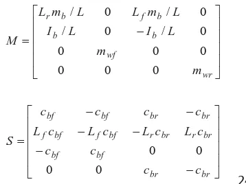
Consider the half car suspension system as shown in Fig. 1. The systems’ equation is represented by
0
Where the state vector, active control vector and excitation vector are respectively given by,
249
Ib is the mass moment of inertia for the vehicle body, mb is the mass for the vehicle body, mwf and mwr are the mass of the front and rear wheels, respectively, xc is the vertical displacement of the vehicle body at the centre of gravity, xbf and xbr are the vertical displacements of the vehicle body at the front and rear suspension locations, respectively, xwf and xwr are the vertical displacement of the vehicle body at the front and rear wheels, respectively, șo is the rotary angle of the vehicle body at the centre of gravity, ffand frare the active controls at the front and rear suspensions, respectively, wfand wr are the irregular excitations from the road surfaces, Lfand Lr are the distances from the front and rear suspension locations, respectively, with reference to the centre of gravity of the vehicle body and Lf + Lr = L. (1) can be rewritten in state space form as follows:
(2)
where
u(t) and z(t) are the control input and the disturbance input respectively.
The state equations of the half-car model in the state space form with the state variables defined as
,
equation shows that the disturbance input is not in phase
with the actuator input, rank
> @
B zrank>
B Bp2@
,therefore the system does not satisfying the matching condition. The analysis with rewriting equation (2) into the following form,
t f t
control input, and the continuous function f t represents the uncertainties with the mismatched condition, rank
>
B f t@
zrank> @
B .III. FUZZY LOGIC CONTROLLER DESIGN
There are specific components characteristic of a fuzzy controller to support the design procedure. They are fuzzification, rule base determination and defuzzification. For this particular system two inputs was used: front body velocity xbfand front body displacement xbf. The
output of the fuzzy control ff and fr are the desired actuator force. A possible choice of the membership functions for the three mentioned variables of the active suspension system represented by a fuzzy set is as shown in Fig. 2, Fig. 3 and Fig. 4.
Figure 2. Membership function of body velocity
Figure 3. Membership function of body velocity
The abbreviations used correspond to:
NB is negative big, NS is negative small, Z is zero, PS is positive small and PB is positive big. The rule base determined by the designer based on the knowledge and experience. The target of the rule base is to minimize the vehicle body acceleration and it is directly will minimize the body displacement as well.
250
Figure 4. Membership function of desired actuator force
Table 1. Rule Base for Membership Function
No Body velocity Body
displacement
Desired output
1 PB PB NB
2 PB PS NS
3 PB Z NS
4 PB NS NS
5 PB NB NS
6 PS PB NS
7 PS PS NS
8 PS Z NS
9 PS NS NS
10 PS NB NS
11 Z PB NB
12 Z PS NS
13 Z Z Z
14 Z NS Z
15 Z NB PS
16 NS PB NS
17 NS PS NS
18 NS Z PS
19 NS NS PS
20 NS NB PB
21 NB PB NB
22 NB PS NS
23 NB Z Z
24 NB NS PS
25 NB NB PB
For example, the linguistic control rules of the fuzzy logic controller obtained from the table above used in such case are as follows:
No 1: IF body velocity is PB AND body displacement is PB THEN desired output is NB
No 20: IF body velocity is NS AND body displacement is NB THEN desired output is PB
The output of the fuzzy controller is a fuzzy set of control. Thus, non fuzzy value must be obtained and in defuzzification step, the method called “centre of gravity (COG)” is used.
³
³
df f
df f f f
D D
P P
(4)
where PD f is corresponding membership function
IV. SIMULATION AND DISCUSSION
The mathematical model of the system as defined in equation (3) and the proposed fuzzy logic controller were simulated on computer. For comparison purposes, the performance of the fuzzy logic controller is compared to the half-car passive suspension system approach. The numerical values for the model parameters are taken from [2], and are as follows:
Table 2. Vehicle Parameter
Car body, mb 575 Kg
Centroidal moment of inertia for the car body, Ib
769 Kg/m2
Front wheel mass, mwf 60 Kg
Rear wheel mass, mwr 60 Kg
Front spring coefficient, kbf 1682 N/m
Rear spring coefficient, kbr 16812 Nm
Front tire spring coefficient, kwf 190000 N/m
Rear tire spring coefficient, kwr 190000 N/m
Front damping coefficient, Cbf 1000 N/m
Rear damping coefficient, Cbr 1000 N/m
Road Profile
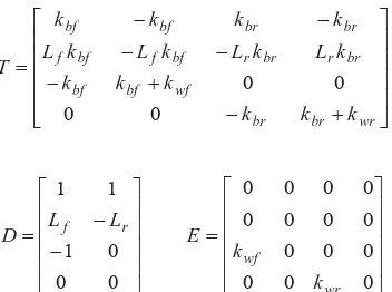
Road profile is represented by a single bump on the road with 5 cm bump height. The mathematical model of the bump for such road is given by as:
¯ ®
0 2 / 8 cos
1 t
a t
w S
elsewhere t 2.5 25 .
2 d d
Where a 5cm and lower time limit is 2.25 second and the upper time limit is 2.5 second. Fig. 6 shows the road profile.
2 2.1 2.2 2.3 2.4 2.5 2.6 2.7 2.8 2.9 3 0
0.005 0.01 0.015 0.02 0.025 0.03 0.035 0.04 0.045 0.05
Time (s)
R
o
ad
pr
of
ile (
m
)
Road profile vs time
Figure 6. Road profile presented a 5 cm bump
251
road handling may be observed through the wheel deflection. There are 4 parameters to be observed in the simulation. The parameters are the body acceleration, wheel deflection, suspension travel and the force to the passenger. In order to make necessary comparison between passive and active suspension, simulations have been carried using MATLAB/Simulink. The results of compared simulated values is discussed.
2 2.5 3 3.5 4 4.5 5 5.5 6 6.5 7
-0.3 -0.2 -0.1 0 0.1 0.2 0.3 0.4
Time (s)
B
o
dy
ac
c
el
er
at
ion
(m
)
Body acceleration (front) vs time
Passive Active
Figure 7(a). Body acceleration comparison between active and passive suspension system (front)
2 2.5 3 3.5 4 4.5 5 5.5 6
-0.8 -0.6 -0.4 -0.2 0 0.2 0.4 0.6 0.8 1
Time (s)
Bo
dy
ac
c
e
le
ra
ti
o
n
(
m
)
Body acceleration (rear) vs time
Passive Active
Figure 7(b). Body acceleration comparison between active and passive suspension system (rear)
2 2.5 3 3.5 4 4.5 5 5.5 6
-0.8 -0.6 -0.4 -0.2 0 0.2 0.4 0.6 0.8 1
Time (s)
W
he
el
de
fl
ec
ti
on (
m
)
Wheel deflection (front) vs time
Passive Active
Figure 8(a). Wheel deflection comparison between active and passive suspension system (front)
2 2.5 3 3.5 4 4.5 5 5.5 6 6.5 7
-0.8 -0.6 -0.4 -0.2 0 0.2 0.4 0.6 0.8 1
Time (s)
W
h
ee
l d
ef
le
c
ti
on
(
m
)
Wheel deflection (rear) vs time
Passive Active
Figure 8(b). Wheel deflection comparison between active and passive suspension system (rear)
2 2.5 3 3.5 4 4.5 5 5.5 6 6.5 7
-2 -1.5 -1 -0.5 0 0.5 1 1.5 2 2.5 3
Time (s)
S
us
pens
ion t
rav
e
l (
m
)
Suspension travel vs time
Passive Active
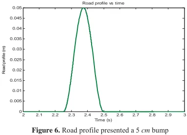
Figure 9. Suspension travel comparison between active and passive suspension system
2 3 4 5 6 7 8
-8 -6 -4 -2 0 2 4 6x 10
5
Time (s)
F
o
rce
(N
)
Force vs time
Passive Active
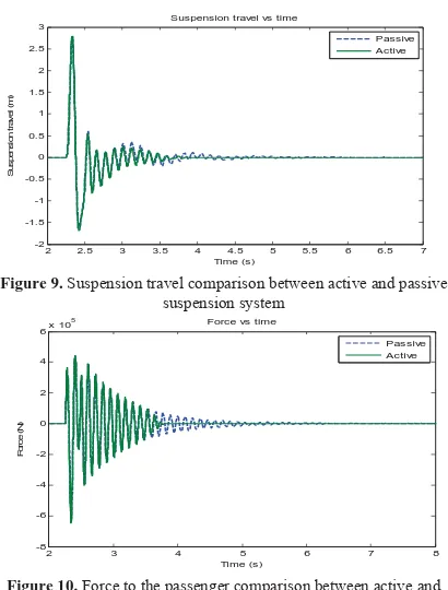
Figure 10. Force to the passenger comparison between active and passive suspension travel
252
system is too soft, it will swing the car hence lost the contact between wheels and the road.
Fig. 9 illustrates the suspension travel for the passive and active suspension system. It is relatives to sprung and unsprung masses. It should always be lesser than the rattle space. Fig. 10 shows the response of force that given to the passenger in passive and active suspension system. From the graph, we can say that the body acceleration is directly proportional to the force. Hence, to reduce the force to the passenger we must decrease the body acceleration. As a result, since we apply the Fuzzy Logic controller into the active suspension system, the force to the passenger is reduce as well as the body acceleration.
V. CONCLUSION
The performances of the active suspension system under the Fuzzy Logic Controller techniques have been evaluated. Comparisons in terms of body acceleration and deflection of such systems have been carried out using the computer simulation works. In overall, the Fuzzy Logic Controller has shown better performances as compared to the conventional half-car passive suspension system.
ACKNOWLEDGMENT
I would like to thank Universiti Teknikal Malaysia Melaka for the research grant that they give me. From the grant, I managed to accomplish this research.
REFERENCES
[1] Yahaya Md Sam, Johari Halim Shah Osman, Mohd Ruddin Abdul Ghani, “Sliding Mode Control Design for Active Suspension on a Half Car Model,” Student Conference on Research and Development (SCOReD) 2003 Proceedings, Putrajaya, pp. 37~42.
[2] A.M. Kashtiban, N.Pourqorban, G.Alizadeh and I. Hasanzadeh, “Nonlinear Optimal Control of a Half Car Active Suspension,”2009 Second International Conference on Computer and Electrical Engineering,” pp. 460~464
[3] M.M.M. Salem and Ayman A. Aly, “Fuzzy Control of a Quarter Car Suspension System,” World Academy of Science, Engineering and Technology 53 2009,” pp. 258 ~ 263
[4] Ali J. Koshkouei and Keith J. Burnham, “Fuzzy Sliding Mode Controllers for Vehicle Active Suspensions,” Control Theory and Application Centre Conventry University
[5] Vinod Kumar and R.R. Joshi, “Hybrid Controller based Intelligent Speed Control of Induction Motor,” Journal of Theoretical and Applied Information Technology,” 2005, pp. 71 ~ 75
[6] Yahaya Md.Sam, Johari Halim Shah bin Osman, ”Modelling And Control Of The Active Suspension System Using Proportional Integral Sliding Mode Approach”, Asian Journal of Control, Vol.7, No.2, pp. 91 ~ 98, June 2005. [7] Appleyard, M. and P.E. Well stead, "Active Suspension:
Some Background," Proc. Contr. Theory App.,Vol. 142, pp. 123 ~ 128 (1995).
[8] Thompson, A.G., "Design of Active Suspension," Proc. Inst. Mech. Engrs, Vol. 185, pp. 553 ~ 563 (1971).
[9] Alleyne, A. and J.K. Hedrick, "Nonlinear Adaptive Control of
Active Suspensions" IEEE Trans. Contr. Syst. Techno!.,
Vol. 3, pp. 94-101 (1997).
[10] Esmailzadeh, E. and H.D. Taghirad, "Active Vehicle Suspensions with Optimal State Feedback Control" J.Mech.
Sci., pp. 1 ~ 18 (1996).