i HUMAN MACHINE INTERFACE DEVELOPMENT
OF A DISTRIBUTION AUTOMATION SYSTEM
Muhammad Azlan Arif bin Sa’adon
ii UNIVERSITI TEKNIKAL MALAYSIA MELAKA
FINAL YEAR PROJECT II
BEKU 4792
TITLE : HUMAN MACHINE INTERFACE (HMI) DEVELOPMENT
OF A DISTRIBUTION AUTOMATION SYSTEM
NAME MUHAMMAD AZLAN ARIF BIN SA’ADON
IC NO. 910903-06-5175
MATRIX NO. B011010067
COURSE BACHELOR OF ELECTRICAL ENGINEERING (CONTROL,
INSTRUMENTATION & AUTOMATION) - BEKC
iii “ I hereby declare that i have read through this report entitle “Human Machine Interface Development of a Distribution Automation System” and found that it has comply the partial fulfillment for awarding the degree of Bachelor of Electrical Engineering (Control, Instrumentation and Automation)”
Signature :
Supervisor’s Name:
iv HUMAN MACHINE INTERFACE (HMI) DEVELOPMENT
OF A DISTRIBUTION AUTOMATION SYSTEM
MUHAMMAD AZLAN ARIF BIN SA’ADON
A report submitted in partial fulfillment of the requirements for the degree of Bachelor of Electrical Engineering (Control, Instrumentation and Automation)
Faculty of Electrical Engineering
UNIVERSITI TEKNIKAL MALAYSIA MELAKA
v I declare that this reports entitle “Human Machine Interface Development of a Distribution Automation System” is the result of my own research except as cited in the references.
The report has not been accepted for any degree and is not concurrently submitted in
candidature of any other degree.
Signature:
Name :
vii ACKNOWLEDGEMENT
First of all, i would like to express my sincere appreciation to my project supervisor, Professor Madya Mohd Ariff bin Mat Hanafiah for encouragement, guidance, motivate and toleration while completing this report. I am also would like to thankful to my co-supervisor Siti Hajar binti Raman for the advice and idea. This project would not
viii ABSTRACT
A distribution automation system (DAS) is a monitoring and controlling power supply grid network system. The most important of this system is the operation reliability to supply the power to the customer efficiently. The outages happen because of an overload in the region supply area. It will affect the critical 24-hours none stop customer such as hospital, financial institutions and many more. The power supply restoration will take longer time while one or second of outages cannot be accepted. This research is to develop a Human Machine Interface (HMI) of a Distribution Automation System (DAS)
as to increase the reliability of the system. In this research, the HMI is capable to monitor and control the system efficiently when there is fault occurring. A data logger is needed to
ix ABSTRACT
Sistem automasi pembahagian ialah sebuah sistem pemerhatian dan pengawalan rangkaian bekalan kuasa elektrik. Kepercayaan terhadap operasi pembekalan kuasa kepada pelanggan secara cekap ialah faktor yang terpenting dalam sistem. Gangguan bekalan elektrik terjadi disebabkan oleh sistem menangung lebihan bebanan. Kesan utama gangguan bekalan elektrik ialah pengguna kritikal yang mengunakan secara seharian seperti hospital, institusi kewangan, dan lapangan terbang. Pemulihan bekalan elektrik juga memakan masa yang lama. Kajian ini ialah untuk membangunkan Human Machine
Interface (HMI) untuk sistem automasi pembahagian untuk meningkatkan lagi kebolehpercayaan terhadap sistem. Di dalam kajian ini HMI berkebolehan untuk
x LIST OF FIGURES
FIGURE TITLE PAGE
1.1 The overview of small scale of DAS 2
2.1 Overview of double chamber substation 5
2.2 Typical flow of electricity 6
2.3 The picture of fibre optic cable 10
2.4 The picture of programmable intergraded circuit (PIC) 11
2.5 The picture of Cytron BB-ACS current sensor 12
2.6 The picture of SK40C 14
xi
3.10 Designing Circuit Using Proteus 33
4.1 The overciew of hardware 37
4.2 The load board ( DC Motor) 40
4.3 The Monitoring Board ( current sensor) 40
4.4 The Overview of HMI 41
4.5 Trending graph 42
4.6 Data Logger for Current 42
4.7 History for overcurrent 43
4.8 Control Panel ( Automatic Mode) 43
4.9 Control Pnale (Switch Deactivated) 44
4.10 Control Panel (Manual Mode) 44
4.11 Conrol Panel (Switch Activated) 44
4.12 Alert Panel 45
4.13 Receive e-mail from control room 45
4.14 The details about the fault and link to direction of substation
46
4.15 The direction to the substation 46
4.16 Virtual serial port driver 49
4.17 Variable data from proteus 49
xii 4.19 Connection of Microcontroller to computer through
UART
50
4.20 Trendng graph drawing input from microcontroller data 51
4.21 The graph of measuring current by using multimeter 53
4.22 The graph of measuring current show at LCD 54
xiii LIST OF TABLES
Table Title Page
2.1 Transformer rating 8
2.2 The comparison between wired and wireless network 10
2.3 The Compariosn between cytron and panucatt current sensor 12
3.1 The Comparison the actual scale and project scale 20
3.2 Current sensor 21
3.4 Microcontroller 22
3.5 Other Components 23
3.6 MikroC source code and explanation 25
3.7 SCADA system Features 32
3.8 Simulation of DC motor 34
3.9 The sequence of LED indicator 34
3.10 Simulation of current sensor (before) 35
3.11 Simulation of current sensor (after) 35
4.1 Coding source code for DC motor 38
4.2 Coding source code for LCD and Current Sensor 38
4.3 Maintenance type 47
4.4 How to set a calendar reminder 48
4.5 Measuring current by using multimeter 53
4.6 Measuring current by using current sensor that display at LCD 54
4.7 Measuring current by using current sensor that display at HMI 55
xiv
2.2 Power Distribution Automation 5
2.3 Distribution Automation System (DAS) 7
2.4 Fault Current 7
2.5.1 Human Machine Interface 9
2.5.2 Communication Network 9
2.5.3 Field Device Network 7
2.5.4 Field Device 11
2.6 Related Previous Works 15
3 DESIGN METHODOLOGY
xv
CHAPTER TITLE PAGE
3.1 Methodology Flow Chart 17
3.2 Research Methodology 19
3.2.1 Project Design 19
3.3 Component Hardware Details 21
3.3.1 DC Motor 21
3.4.1.1 Flow Chart of Programming 24
3.4.1.2 Coding of Programming 26
3.4.2 Proteus Virtual System Modelling 31
3.4.3 Visual Basic (VB) 32
3.5 Simulation of the system 33
3.5.1 Overview 33
4.4 Experiment Result and Discussion 52
xvi
CHAPTER TITLE PAGE
REFFERENCE 58
APPENDIX A 59
APPENDIX B 63
xvii CHAPTER 1
INTRODUCTION
1.1Background
Electricity supply has become one of the most important utilities. However, the
increasing of customer and the demand whether in domestic or commercial cause lots of challenge to the electrical supplier to deliver a better service. Distribution networks are major parts of the total electrical supply system, as it provides the final link between the customer and the bulk transmission system [1].In order to improve the reliability of the system, distribution automation is applied to the system.
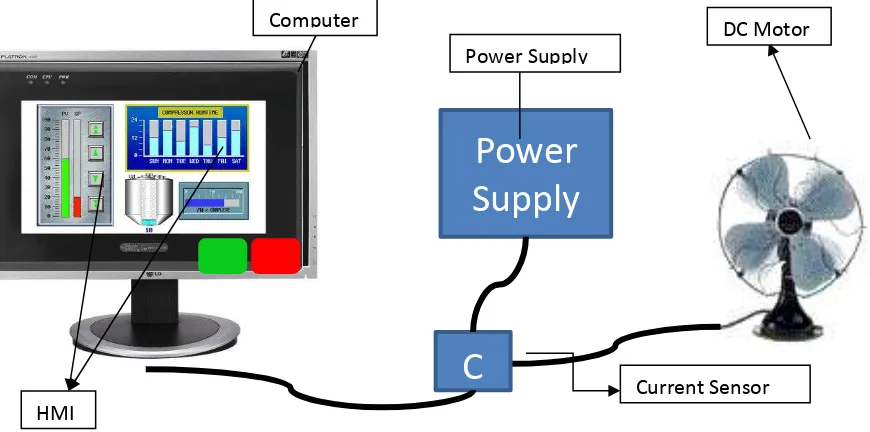
Distribution Automation System (DAS) is a utility’s operation of the distribution power system. A multifunction system to monitor and control the scattered feeder remote terminal unit (FRTU) is the definition of DAS [2]. DAS is based on a centralized system, where the central server receives all information from the field and has full authority of monitoring and control Remote Terminal Unit (RTU) [2].
To improve the reliability of the system, there are many ways and one of it is Supervisory Control and Data Acquisition (SCADA) by using Human Machine Interface (HMI). HMI is a computerized system that between human and machine occur. It is used for maximum supervisory on system, control and receives the feedback of the machine in order to achieve effectiveness of operation [3].
In this project, a small scale of load will be used as emulation of the large scale of DAS. It is because the real scale of DAS is way of scope to bachelor level. Besides that, there is a lot of aspects and protocols need to be considered before applying in real DAS.
Tenaga Nasional Berhad (TNB), one of Malaysian company will not let their system to be tested or simulate to avoid and prevent the interruption to their system that give risk them
cost.
xviii of DC motor will be used to varying the current. The higher the speed of DC motor the higher current uses. When the current is high, it will represent the over current in real DAS that will risky the equipment to damage. When the current is low, it will represent the overload in DAS, which the system cannot afford to supply enough power to consume and will cause the outages.
The five different speeds will be framed by using a current sensor. This algorithm will be sent to computer and will be analysed by Visual Basic software in order to represent the data in a graphical way which is Human Machine Interface (HMI). Form
HMI, it will monitor the current thoroughly from the system. When there are over current or overload occur, the HIMI will cut off the supply to protect the system before damaged whether in automatically or by manual.
xix 1.2 Problem Statement
The electrical supply is affecting a lot in human daily life as to run in domestic or commercial purpose. The reliability of power supply is important for country for developing country and economic growth [2][4].
The outage of electricity would be unacceptable even for one second after fault[2].When the outage occurs it will take so much time to restore back the power supply as the engineer or technician need to troubleshoot the fault location by manually. Outages
can give impact the system failures seriously especially in critical those industries that require 24 hour service such as:
Medical informatics system
Airlines system
Financial institutions
To overcome these outages, Distribution Automation System (DAS) through the Human Machine Interface (HMI) is applied. Distribution Automation System the most important function is to improve the power supply reliability. The DAS will monitor and collecting the data needed for HMI application that will be developed using Visual Basic (VB) software.
1.3Objective
The objectives of this project are:
i) To implemented load current sensor in order to get algorithm for current sensor by using microcontroller and for data logging.
xx 1.4Scope of Research
DAS is a big scale system and there are a lot of aspects and protocols need to be considered. There is no way to Tenaga Nasional Berhad (TNB), the Malaysian utility company to let their DAS to be test by some experiment. It is to avoid the interruption. This project will be implemented in a small size of scale of load system as emulation in order to show that my theory on DAS is capable to increase the reliability of the system.
This project will focus on development of Human Machine Interface (HMI) for Distribution Automation System (DAS) by using Visual Basic Software. The hardware
uses a current sensor to collect the data. The hardware will be used a direct current Motor as a load and will be implemented in five different speed in order to vary the current. The algorithm produced from varying current will be used to set the limitation before the system is outages or over current.
1.5Report Outlines
xxi CHAPTER 2
LITERATURE REVIEW
2.1Theory
In order to develop monitoring and controlling system, the criteria of software and hardware also play role to increase the reliability of the system. Supervisory Controlling and Data Acquisition (SCADA) is a system that monitor and control industrial process by computer controlled [5]. There are four types of SCADA which is Human Machine Interface (HMI), communication network, field device interface and field device [6].
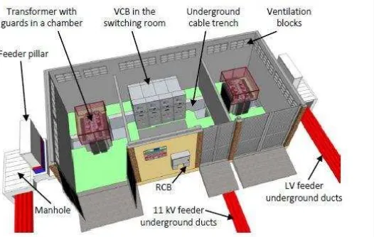
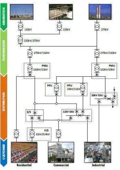
2.2Power Distribution Substation
Power substation is a station that received supply either from Main Intake Substation (PMU), Primary Distribution Substation (PPU) or Primary Switch Station (SSU). Distribution substation is the final station providing electricity to consumer in Power Grid System. In power substation building, it contains of three major electrical equipment which is switchgear, transformer and low voltage distribution board (LVDB). However, the use of transformers is depending on the maximum demands of that area. The larger the demands of power supply, the higher the quantities of transformer.
xxiii 2.3 Distribution Automation System (DAS)
DAS is a multi-function utility’s system to monitor and control the Remote Terminal Unit (RTU). By using a computer, DAS is an automatic controller does not need human force to monitor the system. It be able to increase the efficiency in the context of automation in power supply system. This DAS are equipped with protection system so when there is fault happening, the system will trip to avoid any risks.
2.4Fault Current
Fault current is a situation in which the flow of current that is travelling through an electrical circuit is not within a normal range. There are a lot of causes of fault current and it’s divided into two which is internal and external cause. For the external cause or to be exact is transient fault, is a physical contact that interrupt to the system such as momentary tree contact, animal contact and lightning strike. For internal cause, it happens because of overload that carrying by the substation. As an example if the substations carry maximum demands is 232 kW.
xxiv By using this formula, the substation needs to produce 403.45 Amp in order to supply
maximum demands which is 232kW. In order to select the transformer for the substation, the
transformers must work under 70 percent to 80 percent capacity. If the transformer works more
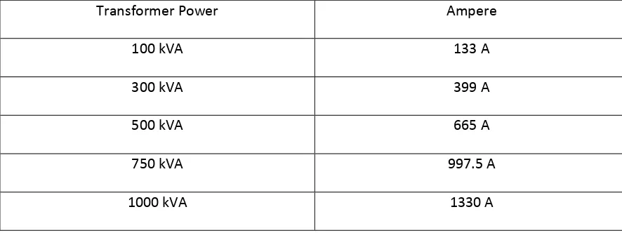
than requirement it will trip the system for protection. According to the Table 2.1 transformer with
power of 500 kVA is selected as it can produce 665 ampere which is more than current maximum
demands which is 403.45 ampere and it makes the transformer works in the range 60 percent
which is meeting the requirement of transformer selection. However, after years, the maximum
demands are larger due to increasing of power supply usage. After years, new maximum demand
now is 400 kW. By using the same formula, the new current maximum demand is 695 ampere
which had made the transformer working over capacity with 104 percent. This situation is called


