UNIVERSITI TEKNIKAL MALAYSIA MELAKA
DEVELOPMENT OF CONTROL SYSTEM BY USING
HMI FOR MAP 201
This report submitted in accordance with requirement of the Universiti Teknikal Malaysia Melaka (UTeM) for the Bachelor of Electronic Engineering Technology
(Industrial Electronics) with Honours
by
MOHAMMAD ARIF BIN ABD AZIZ
B071210320
910605115699
i
DECLARATION
I hereby, declared this report entitled “Development of Control System by Using SCADA for MAP-201” is the results of my own research except as in references.
Signature :……….. Author’s Name : MOHAMMAD ARIF BIN AZIZ
ii
APPROVAL
This report is submitted to the Faculty of Engineering Technology of UTeM as a partial fulfillment of the requirements for the degree of Bachelor of Engineering Technology of Electronic Industrial Hons. . The member of the supervisory is as follow:
iii
ABSTRAK
iv
ABSTRACT
v
DEDICATION
To my beloved parents
ABD AZIZ BIN OMAR
LIJAH BINTI NIK
vi
ACKNOWLEDGEMENT
I wish to express sincere appreciation to Universiti Teknikal Malaysia Melaka (UTeM) for giving me a chance to further my study on Bachelor of Degree in Technology of Industrial Electronic in Faculty of Technology Engineering.
Despite of that, I would take this opportunity to express my profoundest gratitude and deepest regards to all those who gave me the possibility to successfully complete the PSM. I am deeply indebted to my Project Supervisor Encik Shamsul Fakhar bin Gani and wish to express a million thanks for him exemplary guidance, monitoring and constant encouragement throughout the development of this project.
vii
List Abbreviations, Symbol and Nomenclatures ix
CHAPTER 1: INTRODUCTION
1
viii
CHAPTER 3: METHODOLOGY
16
3.0 Introduction 16
3.1 Project Planning 16
3.2 Study the Sequence of MAP 201 and Develop the GRAFCET 18 3.3 Construct the Ladder Diagram 18 3.4 Testing the Ladder Diagram 20 3.5 Implement the Ladder Diagram 20 3.6 Design and Implement HMI on MAP 201 20
CHAPTER 4: RESULT & DISCUSSION
24
ix
LIST OF TABLE
2.1 The Difference between PLC and PIC 6
2.2 Type of Mnemonic Code 7
2.3 Example of Mnemonic Code 7
x
LIST OF FIGURE
2.1 Type of Ladder Diagram 8
2.2 Example of OMRON Ladder Diagram 9 2.3 Basic Architecture of HMI 10
2.4 Example of GRAFCET 11
2.5 SYSMAC MAP 201 12
2.6(a) Through-beam Sensor 13
2.6(b) Retro-reflective Sensor 13
2.6(c) Proximity Sensor 14
2.7 Design of Reed Switch 15
3.1 Flowchart of project 17
3.2 CX-Programmer Setting 18
3.3 Workplace Setting 19
3.4 Symbol Setting 19
3.5 Example of HMI and PLC component 21
3.6 Connector Selection 21
xi
4.7 Example of Power Program 30 4.8 Example of Timer Program 31
4.9 Timer Set Up 31
xii
LIST OF ABREVIATIONS, SYMBOLS AND
NOMENCLATURE
I/O - Input and Output
HMI - Human Machine Interface MTU - Machine Terminal Unit
PIC - Peripheral Interface Controller PLC - Programmable Logic Controller RAM - Random Access Memory
RTU - Remote Terminal Unit
1
CHAPTER 1
INTRODUCTION
1.0Introduction
This chapter is about the whole of the project, why this project be make, the purpose of the project to the human used at the future, an objective of the project and how was this project will be made by showing the project flowchart.
1.1 Background Project
Human Machine Interface (HMI) is generally referred to an industrial control system that a computer system monitoring and controlling a process by using touch panel. The process can be industrial, infrastructure or facility. The industrial process is included those of manufacturing, production, power generation, fabrication, and may run in continuous, batch, repetitive or discrete modes. Besides that, the infrastructure processes may be public or private. This is including water treatment and distribution, waste collection and treatment, oil and gas pipelines, electrical power transmission and distribution, and large communication systems. The facility process is occur both in public facilities and private ones, including buildings, airports, ships, and space stations.
2
Interface (GUI). The graphical User Interface is the page that will be used as the interface to control the system. This (GUI) the user will be able to monitor and control the whole system of MAP 201.
A MAP 201 is a mechanical handling system in which is a station to soft and check the condition of the product are reject or not. It has a few parts to complete the instruction for MAP 201.
1. Gravity feeder houses
This part like a starting point of this station to supply the product. 2. Pneumatic cylinder 1
This cylinder will push the product to the next process 3. Plunger or stamping
This project is basically based on the software called NB-Designer which is implemented on MAP 201. The main control computer will be able to display the flow of process to produce the product. A part of that, it also can control the whole system of the station and can control from touch panel without need to go at station to stop and start the system. It will easily alert human if there is any problem happen can do the mantainence if error happen and all the information can be controlled from the touch panel.
1.2 Problem Statement
3
industrial field, the machine just used the automatic and manual push button for control the system. There are maybe some errors occurs cause by human itself such as bad quality of product, wrong counting of product and low machine safety. Thus, HMI is the best alternative to solve the monitoring system and control all kind of scale of machine. Besides that, the number of products being produces, air pressure, electric supply, machine condition, product measurement and on/off system MAP 201 station directly can be monitored overall by the main control computer.
1.3 Project Objective
The objective of project is to ensure that the project following on the right plan and what the project really wants to achieves. Besides than it also to ensure the positive progress of the development system and also to ensure that the main objective will be realized. Below is the objective of the project:
1. To design and develop control strategy to control MAP 201. 2. To design the Human Machine Interface (HMI)
3. Implement the HMI on the MAP 201.
1.4 Work of Scope
The scope of this project is to determine the method in used and knowledge that used to achieves the objective of the project. Based on the objective, it need to brief clearly for make sure the process to implement is running smoothly.
4
2. The NB-designer software is used to develop the HMI that can integrate with MAP 201. Study about HMI from the manual provided by SMC training Company and then, doing the experiment to identify all the technologies that uses in MAP 201 such as sensor, pneumatic and PLC. NB-Designer is used to design the graphical user interface
5
CHAPTER 2
LITERATURE REVIEW
2.0Introduction
In this chapter, the discussion about the background study of the project along with the literature review is performed and document about the concept of theoretical is applied in completing this project.
2.1 Programmable Logic Controller (PLC)
A programmable logic controller is a digital computer used for automation of industrial processes, such as control a machine on a factory assembly line. PLCs used many type in many difference industries and machines such as packaging the product. The PLC is designed to develop a program that has multiple inputs and outputs arrangement. [1]
The main difference from others computer is that PLC is armored for severe conditions and has the facility for extensive I/O arrangement. These connect the PLC to sensors and actuators. PLC read limit switches, analogue process variables and the positions of complex positioning systems. Some even used machine vision. On the actuator side, PLC operates electric motor, pneumatic or hydraulic cylinder, magnetic relays or solenoids, or analogue output. The I/O arrangements may be built into a simple PLC, or the PLC may have external I/O modules attached to a computer network that plugs into the PLC.
6
[2]modular PLC have a chassis (also called a rack) into which are placed modules with different function. The processor and selection of I/O modules is customized for the particular application. Several racks can be administered by a single processor, and may have thousands of input and output. A special high speed serial I/O link is used so that racks can be distributed away from the processor, reducing the wiring costs for large plants.
PLC programs are typically written in a special application on a personal computer, and then downloaded by a direct-connection cable or over a network to the PLC.[1] The program is stored in the PLC either in battery backed up RAM or some other non-volatile flash memory. A single PLC can be programmed to replace thousands of relays.
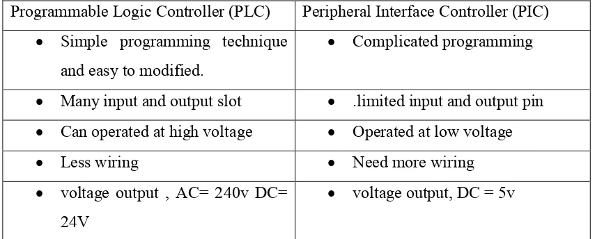
Table 2.1: The difference between PLC and PIC
Programmable Logic Controller (PLC) Peripheral Interface Controller (PIC)
Simple programming technique and easy to modified.
Complicated programming
Many input and output slot .limited input and output pin
Can operated at high voltage Operated at low voltage
Less wiring Need more wiring
voltage output , AC= 240v DC= 24V
voltage output, DC = 5v
2.1.1 PLC programming: Instruction set
7
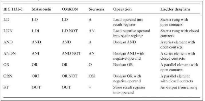
mnemonic codes that different PLC manufactures differ.[3] The Table 2.2 had shown the core mnemonic code for the rest of the following instruction.
Table 2.2: Type of mnemonic codes
Each program instruction consists of two parts; a mnemonic operation component also known as op-code and an address or data component that identifies a particular element within the PLC. The mnemonic code provides exactly the same information as the ladder diagram, but in a form that can be typed directly into the PC. The program is input into address in Program Memory. Each address in Program Memory does not necessarily hold the same amount of data. It holds one instruction and all of the definers and operands required for that instruction (one to four words long). Program Memory addresses start at 00000 and run until the capacity of Program Memory has been exhausted. The Table 2.3 has shown the example of mnemonic code for some instruction from the ladder diagram.
Table 2.3: Example of mnemonic code Address Instruction Data
00000 LD 00000
00001 OUT 01000
8 2.1.2 Ladder diagram
The logic instruction is used as the basic programming for PLC. The form of programming commonly use with PLC is ladder diagram. Each task of the programming is specified as through a rung of ladder. Thus the rung could specify that state of switches A and B be examined and both if both A and B are closed a solenoid, the output will energize.
Figure 2.1: Type of Ladder Diagram
The ladder diagram instruction consist two type of condition which is normally open (NO) and normally close (NC). The condition without diagonal line through them are called normally open condition and corresponds to a LOAD, AND, or OR instructions. Besides that, the condition with diagonal line through them is called normally closed conditions and corresponds to a LOAD NOT, AND NOT, OR NOT instructions. The number above each condition indicates the operand bit for the instruction. It is the status of the bit associated with each condition that determines the execution condition for the following instructions.
9
Figure 2.2: Example of OMRON ladder diagram
2.2 Human Machine Interface (HMI)
Human Machine Interface (HMI) generally refer to control and monitor an operating of machine with code signal over communication channel so as to provide control of remote equipment.[4] This control system is a combination of data acquisition system and something that added to use of coded signal communication channels to acquire information about the status of the remote equipment for display and record. HMI is same like Supervisory Control and Data Acquisition (SCADA) which is the input and output will display and the screen and the human will control the process, and which present process data to the screen. It also one of the system are highly distributed system used to control geographically dispersed assets, often scattered over thousands of square kilometers, where centralized data acquisition and control are critical to system.[5] The system can control or program by using PLC programming. This system is usually using in industrial field to monitor, control and analysis the data or process the data. This system also used to control dispersed assets where centralized data acquisition is as important controller.[5] These systems are used in distribution system such as water distribution waste water.
10
sensor.[6] Figure 2.3 below show the basic architecture of HMI. Based on that, it also used in industrial automation control system at the many modern industries such as:
I. Energy industry II. Food and beverage III. Oil and gas
IV. Power plant V. Recycling Process VI. Transportation
Figure 2.3: Basic Architecture of HMI
2.3 GRAFCET
11
The control system of GRAFCET can be broken down into a succession of concise and easy to read, enabling the description of the functions by the automatic equipment. It is capable of describing the sequence of states of a discrete-event system which may contain a very large number of states. It will take into account the concurrency for both simplicity and easy to understand. In general, only a few input will affected to the state and only a few output may change based on the state of system.[7] The GRAFCET will show clearly about the input and output of the system behavior of a logic controller.
Figure2.4: Example of GRAFCET
Based on the Figure 2.4 above, GRAFCET is the development of a committee for the standardized the specification of logic control system. It have a basic concept of the model is quite clear and simple. That is state, step, transition and the condition associated to transition.
I. The State can be defined as the memory of specification and their activity is characteristic of the steps. It will represented by KEEP Relay or Internal Relay in the PLC instruction.