Vol.2 No.6 pp.306–314 DOI: 10.1541/ieejjia.2.306
Paper
Formal Verification of Logic Control Systems
with Nondeterministic Behaviors
Saifulza Alwi
∗,∗∗Non-member,
Yasutaka Fujimoto
∗ Member(Manuscript received Nov. 14, 2012, revised June 2, 2013)
This paper describes a formal modeling and verification of an arm pick-and-place system, in which nondeterministic behaviors of the arm state condition and timer function blocks are applied. We design an appropriate PLC program using a ladder diagram (LD) for the arm pick-and-place operation and apply in it a situation where the arm may drop the product or material being gripped because of an external force. In addition, the timer function blocks are used with formalization of their finite-state logical properties. We use an actual model of the arm to verify that safe operations are established for normal product pick-and-place, as well as when the product has fallen. In addition, we perform arm model verifications for five important temporal properties using the NuSMV model checker. We present two types of experiments to validate the safety of the designed LD program. We also verify that the nondeterminism that appears as a result of the system behaviors can be formalized and used to represent logical assumptions for the properties that need to be verified.
Keywords:programmable logic controllers, formal methods, formal verification, model checking, timer function blocks
1.
Introduction
Logic control system design using programmable logic controllers (PLCs) is currently becoming more complicated because of the various embedded features and functionality requirements that are now used. The main concern when de-signing such a control system, especially in manufacturing automation processes, is how to deal with safety and relia-bility. In industry, for example, formal methods are used as verification procedures to check whether a system satisfies the desired safety specifications(1)
so that if any unintended behavior is identified, it can be eliminated before a mass pro-duction process is started.
Among several formal verification approaches, temporal logic model checking is a popular technique for verifying that a system satisfies its specifications. The system is usu-ally formalized as a Kripke structure and the specification are described as a temporal logic formula. Model checking is in-tended to check that the Kripke structure is a model of the temporal logic specification. Otherwise, the model checker produces a counterexample that shows the location at which the model violates the specified temporal properties.
PLC formal verification is an essential procedure to ver-ify the correctness of a control program prior to implemen-tation so that any design errors can be amended. In many cases, a PLC program that represents a control system is of-ten designed deterministically, such that the outputs are al-ready predicted according to the given inputs, even if the
∗Department of Electrical and Computer Engineering
Yokohama National University
79-5, Tokiwadai, Hodogaya-ku, Yokohama 240-8501, Japan
∗∗Faculty of Electrical Engineering, Universiti Teknikal Malaysia
Melaka (UTeM)
Hang Tuah Jaya, 76100 Durian Tunggal, Melaka, Malaysia
same inputs are given repeatedly at different times. However, when the environment of the system is not fully predictable because of the presence of an underlying behavior or external input forces, the system can be considered nondeterministic. Nondeterminism often exists due to underspecification of the process design and development, or implementation choice.
In this paper, we introduce a formal modeling and verifi-cation of PLC nondeterministic behavior in which a ladder diagram (LD) is implemented. We provide an illustrative ex-ample using an arm pick-and-place model, and design the LD program for the arm, with the application of timer ON and timer OFF (namely TON and TOF, respectively) function blocks. The nondeterministic behaviors are configured from an arm grip condition and also from the logical formalism of both timer properties. By applying five temporal properties to the arm model, we verify the deterministic and nondeter-ministic behaviors, and present two experimental results for validation of safe arm operation. The contributions of this work are:
( 1 ) safety verification and validation through experi-ments using an arm pick-and-place operational model with nondeterministic behaviors
( 2 ) model verification using temporal properties with inclusion of nondeterministic behaviors from state op-erations and timer functions
( 3 ) application of TOF timer function block for safety experiments with reachability and the implementation of liveness property checking
2.
Related Studies
In a paper describing a comprehensive study of the appli-cation of formal methods, Seidner et al.(2) proposed a
Moreover, an approach of reusable automation components (RACs)(3)that introduces a formal specification defining the
correct use and behavior of industrial system’s components has led to shorter development and modification times. In re-cent publication, the same authors propose and apply a work procedure of developing safety PLC programs with formal specifications that relevant for implementation in industry(4)
. Additionally, the use of timing functions play an impor-tant role in PLC for real time applications. The formalization of timers application for PLC control programs at abstract level is explained thoroughly by Hai Wan et al.(5). In this
paper, they have formally proved the correctness of PLC pro-grams by using Coq theorem prover, in which the timer con-trol is applied. The same theorem prover tool was then uti-lized to formalize the semantics of Instruction List (IL), one of the common programming language in PLC, that also in-cludeson-delay timers(6). Several safety properties have been
proved by using this semantics.
Prior to that, a formal semantics for LD programs that use timer function blocks was introduced in(7). They deal
withTime ON delayfunction blocks (TON) at a logical level. Some of our works presented in this paper are inspired from their approach. Instead of LD, Loeis et al. utilized IL to de-scribe the control system behavior and conduct the verifica-tion using Binary Decision Diagram (BDD) and SAT tech-niques(8). Rausch and Krogh(9)in their paper also presented
the same approach by using Symbolic Model Verifier (SMV), an old version of NuSMV.
The studies in PLC modeling for logic verification was also conducted because of the awareness of the importance of safety and reliability of control system in industry(10).
Fur-thermore, an advanced method by performing model check-ing directly from IL was conducted, and the advantage is that the counterexample is produced in the IL itself(11). The
other language in PLC programming also is implemented for model checking approach for the purpose of evaluating the safety of PLC control systems(12).
Generally, control systems with deterministic specifica-tions such as the ones designed using PLCs are easy to be verified. However, with complex and modern system imple-mentations, nondeterministic behaviors due to concurrency, non-controllable elements etc. cannot be neglected(13). To
overcome the difficulties in dealing with nondeterminism, a method of test case generation from model checker coun-terexamples was proposed. This approach is based on modu-lar model checking of mutant composition by fault modeling and specifications(14)
. Gordon et al. implemented a test case derivation technique from nondeterministic models by apply-ing counterexample evaluation(15).
3.
Operational Semantics for PLC Program
We give an overview of operational semantics for PLC pro-gram, which is described in LD. This also can be considered as a formal definition of abstract behavior of a LD program. There are some restrictions apply for simplification of for-mal semantics definition, based on IEC 61131-3 standard(16)
. However, still the considered LD program has taken into ac-count all contacts described in the IEC 61131-3, including TON and TOF function blocks and set/reset output coils. We assume in detail that:
( 1 ) all variables are boolean
( 2 ) each LD rung is composed of a testing part (test contacts and combination wires) followed by an as-signment part(output coils)
( 3 ) the rungs are evaluated sequentially, from top to bottom
Finally, we assume that the LD program runs in acyclic PLC. This behavior is described in the IEC 61131-8 standard.
4.
Timer Function Blocks
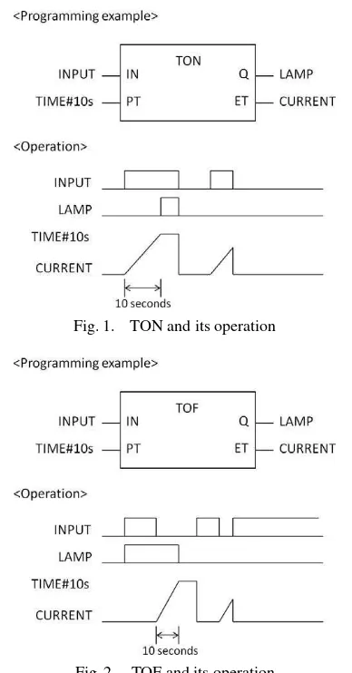
In this section, we explain the operational semantics of two most common-used timer function in PLC, named as time ON delay (TON) and time OFF delay (TOF) function blocks. 4.1 Time ON Delay (TON) Time ON delay function block (afterwards referred as TON) is basically used to de-scribe ON timing delays in LD programs. Their behavior is explained in detail in the IEC 61131-3 standard. An example of a TON and its operation is illustrated in Fig. 1. The TON is always used in the testing part of the rung. We give the stan-dard definition of the TON behavior as follow: An internal float variableETmeasures theelapsed time(increases along with the internal clock of the PLC) as long as inputINholds TRUE, and then outputQis FALSE.ET is set to 0 whenIN is FALSE. It is also compared to inputPT: ifET =PT, then Qis set to TRUE, andET is no longer increased. Our formal model is an abstract simplification of the above behavior. We only keep a logical view of the trigger condition (ET =PT) without taking into account the explicit timing values.
We assume there are three internal states that can be ob-served from the abstract model of a TON:inactive(I), run-ning(R) ortriggered(T). The transition system from one to another state of the TON module is described in detail in 5.: a running (R) state of TON can either stay in state R or T, in a nondeterministic way. Qis set to TRUE when the TON is triggered. During some evolution of the TON block, the inputINholds FALSE, then the state of the TON is set to I.
4.2 Time OFF Delay (TOF) Similar to the TON function block (afterwards referred as TOF), an example of a TOF function and its operation is illustrated in Fig. 2. The standard behavior of the TOF is as follows: An internal float variableETmeasures theelapsed time(increases along with the internal clock of the PLC) once the input variable IN becomes FALSE, and then output Q remains TRUE if ET PT. ET is set to 0 whenQis FALSE. It is also com-pared to inputPT: ifET =PT, thenQis set to FALSE, and ET is no longer increased.
Similar to TON, the assumption is that there are three in-ternal states of a TOF function block:inactive(I),running(R) ordeactivated(D). A running TOF can either be in state R or D, in a nondeterministic way.
These finite-state logical views of both TON and TOF lead to a simple model that can be smoothly integrated in the transition relation for any arbitrary logical system. The ap-proach presented here has its limitations compare to quanti-tative modelings of the real time aspects, but it is safe: any safety property satisfied by the model is also true in the quan-titative model based on timed-automata.
4.3 Integration of Timer Function Block and LD
Fig. 1. TON and its operation
Fig. 2. TOF and its operation
in any rung, an additional internal variable encodes the inter-nal state (Q, R or I) of that TON block is required. Evaluat-ing the rung with a TON block requires the evaluation of the next state of the TON block, which may depend on the test-ing part. Here theINinput value is not uniquely determined since it may become TRUE or FALSE nondeterministically. Then the current value of output Q is known and usual evalu-ation of a rung can be pursued. The behavior can be modeled in the associated variable by inserting a new control point in the rung where a TON block occurs. If there are more than one TON block exist, they sequentially evaluated from left-to-right, top-to-bottom order.
5.
Modeling and Experiments
This section reports an illustrative example, providing an arm pick-and-place system for formal modeling of deter-ministic and nondeterdeter-ministic behaviors. Generally, the arm pick-and-place system is commonly used for product or ma-terial handling system. In our case, we use the arm model for experiments as in Fig. 3. We provide a plant model of the arm that describes the model configuration, then we design the LD program on the basis of its regular operation, and also integrating the program with TON and TOF function blocks. To verify whether the designed LD program meets the specified properties, we consider a number of temporal logic specifications, such as invariance and liveness prop-erty described in CTL formulae. We verify the arm system
Fig. 3. Actual arm model
whether it satisfies the specified properties by using NuSMV tool, a SMV based extended model checker.
The arm pick-and-place system uses a MICREX-SX SPH series of PLC with D300win programming software (Fuji Electric Corporation), whereas the PLC programming tool is based on the IEC 61131-3 standard.
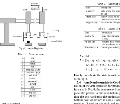
5.1 Experimental Setup The operational diagram is illustrated in Fig. 4 to facilitate the analysis and design of the LD program. The definition of states, where all variable x stands forstate inputsand all variableustands foractuator outputsare summarized in Table 1. All the state variables are represented withxiandui. Here, we setu5andu6as internal variables because they are not the actual output variables of the system. We also integrate the LD program with a TON and two TOF function blocks. The internal states for both type of the timer function blocks are summarized in Table 2 and Table 3, respectively. We particularly focus on the imple-mentation of nondeterministic behavior to grip condition and the timer functions, which are described in detail in 5.4 and Section 7.
5.2 Arm Pick-and-Place Operation A complete op-eration of the arm pick-and-place can be described in the fol-lowing order:
( 1 ) arm moves backward to the rear-top position from the front-top (home) position
( 2 ) from the rear-top position, arm moves downward to the rear-bottom position
( 3 ) at the rear-bottom position, arm hand picks and grips the product (state of the grip changes from close
=FALSE, open=TRUE to close=FALSE, open=
FALSE)
( 4 ) arm moves upward to the rear-top position while gripping
( 5 ) arm moves forward to the front-top position while gripping
( 6 ) arm moves downward to the front-bottom position while gripping
( 7 ) at the front-bottom position, arm places and releases the product (state of the grip changes from close =
FALSE, open =FALSE to close =FALSE, open =
TRUE)
Fig. 4. Arm diagram Table 1. States of arm
x0 rear
x1 front
x2 bottom
x3 top
x4 open state (grip)
x5 close state (grip)
u0 backward
5.3 Transition System of Arm Model To represent the full arm model as a finite state system, we describe it as a tupleT S =S,Act, δ,I,AP,Lwhere
S: set of states Act: set of actions
δ: transition relation ofS ×Act×S
I: set of initial states
AP: set of atomic proposition L: labeling function ofS →2AP
Then from the model, we obtain the set of states as in the following equations, represented bys0,s1,· · ·,s5.
Therefore, the full model can be represented by the following equations.
Table 2. States of TON
State Description
inactive (I) state where the input variable IN is FALSE
running (R) standby mode where the preset time is calculated until ET=PT
triggered (T) the output variableQis TRUE
Table 3. States of TOF
State Description
inactive (I) state where the input variableINremains TRUE
running (R) standby mode where the preset time is calculated until ET=PT
deactivated (D) the output variableQis FALSE
I={s0} · · · (5) L={(s0,{x1,x3}),(s1,{x0,x3}),(s2,{x0,x2}),
(s3,{x1,x2}),(s4,{x0,x2,x4,x5}),
(s5,{x1,x2,x4,x5})} · · · (6)
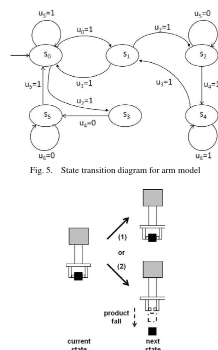
Finally, we obtain the state transition diagram of the model as in Fig. 5.
5.4 Arm Nondeterministic Condition In normal sit-uation of the arm operation for product pick-and-place as il-lustrated in Fig. 4, the arm moves from its home position and picks the product at the rear-bottom position. At this posi-tion, the arm hand grips the product and brings it to the front-bottom position before releases it and moves back to home position. Based on this pick-and-place movements, we as-sume that the nondeterministic situation might be occurred by considering the following conditions:
( 1 ) a normal condition where arm hand continues to grip (close=FALSE, open=FALSE) the product un-til front-bottom position, or otherwise;
( 2 ) an unexpected condition where the product fell down in the middle of the operation because of ex-ternal force (state of the grip changes from close =
FALSE, open = FALSE to close = TRUE, open =
FALSE)
Both conditions are illustrated in Fig. 6.
6.
NuSMV and CTL Temporal Logics
NuSMV is a model checker that has been reengineered from Symbolic Model Verifier (SMV), its earlier version, developed by Carnegie Mellon University (CMU). It is de-signed to be a well structured, open, flexible and documented platform for model checking. User can easily getting famil-iar with NuSMV because its code is relatively easy to modify, achieving outstanding efficiency in order to control the state explosion during verification process. The NuSMV input lan-guage is designed to allow for the description of finite state systems.
Requirements for verification of a finite state system are basically its state transition system and specifications that ex-pressed in propositional temporal logics. Two useful tem-poral logics areComputation Tree Logic (CTL) andLinear Temporal Logic (LTL)(17). Both of them can be described
Fig. 5. State transition diagram for arm model
Fig. 6. Arm nondeterministic condition
specification of intended properties.
The syntax of CTL formulas is given by the following rules:
( 1 ) any atomic proposition is a CTL formula;
( 2 ) ifαandβare CTL formulas, thenα•βand¬αare CTL formulas, where•is any boolean connective (∧,
∨,· · ·);
( 3 ) if α and β are CTL formulas, then AFα, EGα,
E[α∪β]are CTL formulas.
The CTL formulas are constructed frompath quantifiersand temporal operators. Intuitively, path quantifiers are repre-sented by alphabet (A)which means “for every path” and
(E) for “there exists a path”. In a CTL formula, the path quantifiers can be mixed to form an intuitive temporal logic. Meanwhile, the temporal operators are represented by(X)for “next time”,(F)for “sometime in the future”,(G)for “ glob-ally in the future” and(U)for “until”. Some of typical CTL formulas are:
•EF(p∧ ¬q): it is possible to get to a state wherepholds butqdoes not hold.
•AG(EFp): from any state it is possible to get topstate.
•AG(p−>AFq): ifpoccurs, then it will be eventuallyq.
•p∪q:pholds untilqholds.
7.
NuSMV Model
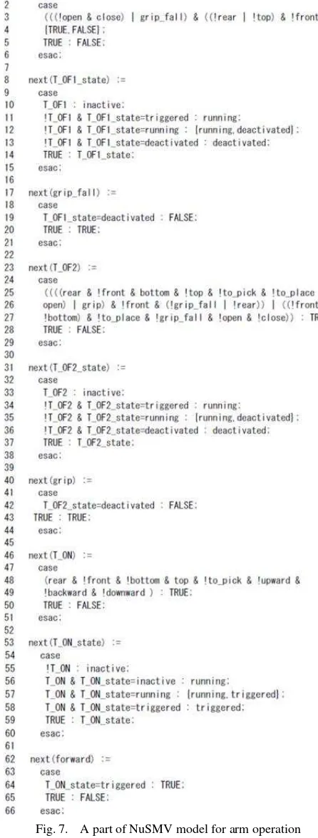
A part of NuSMV model for the arm operation is shown in Fig. 7, which describes the transition relations for all vari-ables with nondeterministic cases, including the TON and
TOF timer functions. The transition relations are written in terms of thecurrentandnextvalues of the state variables, us-ingnextandcasesyntax. Any current state/next state pair is in the transition relation if and only if it satisfies the formula. Below are some descriptions of the model.
•There are one TON and two TOF (TOF1 and TOF2) timer functions used in the model
•Each variableT ON,T OF1andT OF2represents the state for TON, TOF1 and TOF2, respectively
•The transition relation for T OF1 is nondeterministic
({TRUE,FALSE}in line 4 of Fig. 7 means the output can be TRUE or FALSE, nondeterministically)
•The internal state of TON is represented by nondeter-ministic variableT ON stateas in transition relation in lines 53–60
•Theinternalstate of TOF1 is represented by nondeter-ministic variableT OF1 stateas in transition relation in lines 8–15
•Theinternalstate of TOF2 is represented by nondeter-ministic variableT OF2 stateas in transition relation in lines 31–38
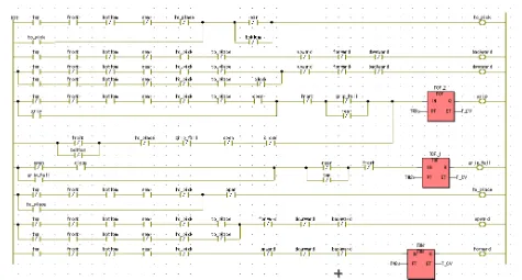
This NuSMV model is directly transformed from the de-signed LD program for experimental verification. The LD program is illustrated in Fig. 8. Note that in the LD program,
•Variable T ON is represented by TON function block at rung 8.
•Variable T OF1 is represented by TOF 1 function block
at rung 5.
•Variable T OF2 is represented by TOF 2 function block at rung 4.
To model the TOF1, we evaluate the contact variables on the left part of TOF 1 function block. The transition relation is described in lines 1–6 of Fig. 7. Similar procedure is per-formed for TON and TOF2 where the transition relations are described in lines 46–51 and lines 23–29, respectively. The only difference is that the TOF1 is evaluated nondeterminis-tically.
Meanwhile, the internal state of TOF1, represented by vari-able T OF1 state as explained previously is also evaluated nondeterministically, leads to any one of three conditions, which isinactive (I),running (R)or deactivated (D). The transition relation for this variable is shown in lines 8–15. Similar case for internal state of TON (variable T ON state) and TOF2 (variable T OF2 state) where the transition rela-tions are described in lines 53–60 and lines 31–38, respec-tively.
Furthermore, the transition relation for grip fallvariable is shown in lines 17–21, which the value is determined by the internal condition of T OF1 state. The actuation variable
gripis evaluated by the internal condition of T OF2 state, described in lines 40–44 andforwardvariable is determined by T ON state, as in lines 62–66.
8.
Verification Results
We perform five temporal properties checking to verify whether the LD program for the arm model that is trans-formed into the NuSMV codes satisfies the temporal speci-fications below.
example,always at most one state only for critical operation is stating that bad thing (having two or more critical states simultaneously) should never occurs(18). Another case of
typ-ical safety property is deadlock freedom. The safety proper-ties are particularly invariants. Invariants are the properties that are given by a conditionΦfor the states and require that
Φholds for all reachable states.
To verify this property, we provide two examples of invari-ant condition for the arm model:
( 1 ) product is gripped(close=FALSE) andproduct is fell(close=TRUE) must not be ON simultaneously ( 2 ) forward or backward actuation is not allowed when
arm is at the bottom position
The verification results using the NuSMV model checker with CTL temporal logics for both specified conditions above are TRUE as in lines 1–3 of Fig. 9, which prove that the arm safe operation holds for both temporal specifications.
The second NuSMV specification above is actually too simple for verifying safety. In real implementation, the safety conditions for a system could be more complicated, with larger number of variables in a single specification. We prove this case by adding other variables to the NuSMV temporal specification in line 3, becoming a more complex specifica-tion as shown in lines 4 and 5 of the same figure, then ver-ify whether the model satisfies this extended safety property. This specification is also intuitively TRUE, saying that the model is correct to satisfy the safety property.
8.2 Reachability An example of reachability prop-erty checking is by investigating that a system iseventually resettable no matter whatever happens in the middle of the operation. We verify this property by evaluating the situation of whatever happens to arm operation, it is possible to get back to home position. The home (initial) position for the arm pick-and-place is thefront-topposition. Verification re-sult of this property checking is described in line 6 of Fig. 9, proving that for any circumstances of the arm state operation, it is possible to get back to home position. Another option for the reachability property checking is to reformulate the speci-fication to be more strict, evaluatingwhatever happens to arm operation, it isalwaysreturn to home position, described by specification in line 7 of Fig. 9 that also resulted to TRUE.
8.3 Safe Operation Experiment with Reachability
In order to verify the reachability through actual system, we conduct two types of experiment, which are:
( 1 ) asafe operationexperiment; the arm stops at home position after product has fallen
( 2 ) anunsafe operationexperiment; the arm moves to the front-bottom position even after product has fallen and return to home position
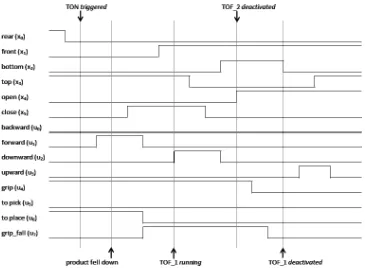
to prove that the arm model is performing operation that sat-isfy the reachability properties described in lines 6 and 7 of Fig. 9. Result of experiments are described using the tim-ing diagram that represents ON-OFF state changes of each variable involved. The timing diagram in Fig. 10 represents the safe condition experiment, while Fig. 11 shows the timing diagram for the unsafe condition experiment. Both timing di-agram of experiments are captured by applying the same LD shown in Fig. 8.
We define the safe operation experiment by assuming that when the product has fallen, the arm should stop or return
Fig. 7. A part of NuSMV model for arm operation
Fig. 8. LD for arm pick-and-place with integration of timer function blocks
Fig. 9. Verification results
forgrip.
For unsafe operation, we give a condition that the prod-uct has fallen not at the top-rear, but whenforwardactuation is occuring. Just after the product has fallen, the arm starts to fully close and reaches front-top position. However, this time thedownwardactuation is occured and TOF 1 starts to count for deactivation. A moment after,gripis fully open at front-bottom position and TOF 2 is deactivated. TOF 1 deac-tivation occurs just before theupwardactuation and the arm returns to home position. In other words, a slight delay of product fallen condition causes the difference in the arm grip open-close timing, resulted to safe and unsafe movements of arm pick-and-place system.
In both of the timing diagrams, the horizontal axis repre-sents time while vertical axis reprerepre-sents the ON-OFF state change for each variable used in the LD program.
8.4 Liveness As the safety properties specify that something bad never happens, the complementary properties can be specified assomething goodwill happen in the future. This is calledlivenessproperties. The violation of the live-ness properties is run in infinite time, while for safety, the properties is violated in finite time, i.e., by finite system run.
A typical example of a liveness property is the requirement that certain events occur infinitely often. This description means thegood eventof a liveness property is a condition on the infinite behaviors. Based on the experimental model, we give two examples of liveness property to be verified stated by the conditions that:
( 1 ) when the arm starts to grip, it is possible to reach bottom position, and conversely;
( 2 ) when product is fell, the arm will not suppose to reach front-bottom position.
We formulate the CTL temporal formulas for both conditions in lines 8 and 9–10 of Fig. 9 respectively and the verifica-tion results indicate TRUE, proving that the liveness property holds for both cases. Similar to the case of reachability prop-erty described previously, the CTL temporal formula AG(p
−>EFq) is sufficient to express the possibility of a required state holds in the future, rather than AG(p− >AFq). The latter formula is a stronger requirement, which interpreted as when p occurs, then it will be eventually q.
Fig. 10. Safe condition experiment (the arm stops at home position after product has fallen)
Fig. 11. Unsafe condition experiment (the arm moves similar to normal operation even the product has fallen)
will eventually be triggered upon satisfying the input variable condition.
8.6 Fairness for Liveness As previously explained in subsection 8.5, the operational model of both TON and TOF described only allows eventual triggering or deactivat-ing. The restriction of this nondeterministic behavior would be appropriate by assuming that the TON will eventually trig-ger by associating with the definition of fairness constraint (restriction the set of possible runs). For example, we can state that if the TON is in the (R) state and infinitely often
evaluated, then if the input variable holds, the TON will even-tually trigger (T). The logical evaluation in lines 13 and 14 of Fig. 9 describes this condition. In the LD program for the arm model, once the TON is triggered, the arm moves to the front position.
options. We assume that the specified fairness constraint for the TON is an unconditional fairness, because both (R) as well as (T) states are ready to be execute infinitely often.
Similar situation is observed from the TOF liveness prop-erty because it depends on the implementation choice of whether the arm might be fully closed (close=TRUE) af-ter the product has fallen, or the arm continues gripping the product (close=FALSE) before placement. The difference compares to TON is that its input variable need to be FALSE before the selection of{running,deactivate}is made.
Five temporal properties verification for the arm model explained above are examples to prove the intuitiveness of NuSMV model with specifications, as well as to validate that the designed LD program is performing desired operation that meets the specified requirements. The nondeterministic behaviors from the arm grip condition and the timer logical properties are formally verified using the CTL temporal spec-ifications. For the case of timer, we take an example of TON behavior, and suppose the TOF is also operated in a similar condition. In addition, from the experiments we prove that the reachability property is fulfilled for both safe and unsafe operations.
9.
Conclusion
In this paper, we presented a formal method approach, which is to formally verify a model with nondeterministic conditions occured from the system behaviors. We use an example of a material handling system, which is an arm pick-and-place model to verify five substantial temporal properties by using NuSMV model checking tool, and also conducted safety experiments to check that the designed LD program for the arm model satisfies the predetermined safety condi-tion. The experimental results also prove the reachability property, which the arm return to its initial state, regardless of safe or unsafe operation. The logical properties of TON and TOF timer function blocks can be used to automatically prove some liveness properties with fairness constraint evaluation. The formalism of these timer functions from logical view-point avoids the complexity of model checking method by timed-automata. We conclude that the NuSMV model with CTL temporal specifications used in this work can be applied to validate the correctness of LD programs, as well as to ver-ify the nondeterministics behaviors of logic control system.
Acknowledgment
The author would like to thank Universiti Teknikal Malaysia Melaka (UTeM) and Ministry of Higher Education, Malaysia for their financial support and advice in pursuing a Ph.D. study at Yokohama National University.
References
( 1 ) G. Frey and L. Litz: “Formal methods in PLC programming”, in Proc. 2000 IEEE Conf. Syst. Man, Cybern., Vol.4, pp.2431–2436 (2000)
( 2 ) C. Seidner and O.H. Roux: “Formal Methods for Systems Engineering Be-havior Models”, IEEE Trans. Industrial Informatics, Vol.4, No.4, pp.280–291 (2008)
( 3 ) O. Ljungkrantz, K. Akesson, M. Fabian, and C. Yuan: “Formal Specifica-tion and VerificaSpecifica-tion of Industrial Control Logic Components”,IEEE Trans. Automation Sci. and Engineering, Vol.7, No.3, pp.538–548 (2010) ( 4 ) O. Ljungkrantz, K. Akesson, C. Yuan, and M. Fabian: “Towards Industrial
Formal Specification of Programmable Safety Systems”,IEEE Trans. Con-trol Systems Technology, Vol.20, No.6, pp.1567–1574 (2012)
( 5 ) H. Wan, G. Chen, X. Song, and M. Gu: “Formalization and Verification of PLC Timers in Coq”, in 33rd Annual IEEE Int. Computer Software and Ap-plications Conf., USA (2009)
( 6 ) S.O. Biha: “A formal semantics of PLC programs in Coq”, IEEE Computer Software and Applications, COMPSAC (2011)
( 7 ) O. Rossi and Ph. Schnoebelen: “Formal modelling of timed function blocks for the automated verification of ladder diagram programs”, in Proc. Int. Conf. Automation of Mixed Processes and Hybrid Dynamic Systems, Ger-many, pp.177–182 (2000)
( 8 ) K. Loeis, M.B. Younis, and G. Frey: “Application of Symbolic and Bounded Model Checking to the Verification of Logic Control Systems”, in 10th IEEE Conf. Emerging Technologies and Factory Automation (2005)
( 9 ) M. Rausch and B.H. Krogh: “Formal verification of PLC Programs”, in American Control Conference, USA (1998)
( 10 ) II Moon: “Modeling programmable logic controllers for logic verification”, IEEE Control Systems Magazine, Vol.14, No.2, pp.53–59 (1994) ( 11 ) B. Schlich, J. Brauer, J. Wernerus, and S. Kowalewski: “Direct Model
Check-ing of PLC Programs in IL”, in 2nd IFAC Workshop on Dependable Control of Discrete Systems (2009)
( 12 ) R. Huuck, B. Lukoschus, and N. Bauer: “A Model-Checking Approach to Safe SFCs”, in IMACS Multiconference on Computational Eng. in Syst. Ap-plications, France (2003)
( 13 ) A. Jain, K. Nelson, and R.E. Bryant: “Verifying Nondeterministic Imple-mentations of Deterministic Systems”, in Formal Methods in CAD, Springer-Verlag, pp.109–125 (1996)
( 14 ) S. Boroday and A. Petrenko: “Can a Model Checker Generate Tests for Non-Deterministic Systems?”, Electrical Notes in Theoretical Computer Science 190, Elsevier, pp.3–19 (2007)
( 15 ) G. Fraser and F. Wotawa: “Test-Case Generation and Coverage Analysis for Nondeterministic Systems Using Model-Checkers”, in Int. Conf. on Software Engineering Advances (2007)
( 16 ) IEC, Programmable Controllers-Part 3: Programming Languages, 2nd ed. ser. International standard IEC 61131-3, International Electrotechnical Com-mission (2003)
( 17 ) H. Iwashita, T. Nakata, and F. Hirose: “CTL model checking based on for-ward state traversal”, in Proc. of IEEE/ACM Int. Conf. of Computer Aided Design, Washington (1996)
( 18 ) C. Baier and J.P. Katoen: “Principles of Model Checking”, The MIT Press, Cambridge (2008)
Saifulza Alwi (Non-member) received a Master degree in Computer Science and Systems from Kyushu Institute of Tech-nology in 2003, and is presently a Ph.D. candidate at Yokohama National University. He is also currently attached to Universiti Teknikal Malaysia Malaysia (UTeM) as a lecturer. His research interests include automated V&V of logic control system and PLC software technology for factory automation.