1 This chapter introduces the general idea of this project and provides the problem
statement, objectives, and project scope. This chapter also provides a report
organization to briefly introduce about the purpose of all the generated chapters.
1.1 Background
Nowadays, the new wave of computer technology makes a crucial impact on modern
world. Desktop computer is widely employed in state-of-the-art industry and more
data are capable to be processed with a tremendous speed due to rapid development
of IT. This capability not only leads to higher density of heat and increases heat
dissipation of personal computer, but also causes the temperature of central
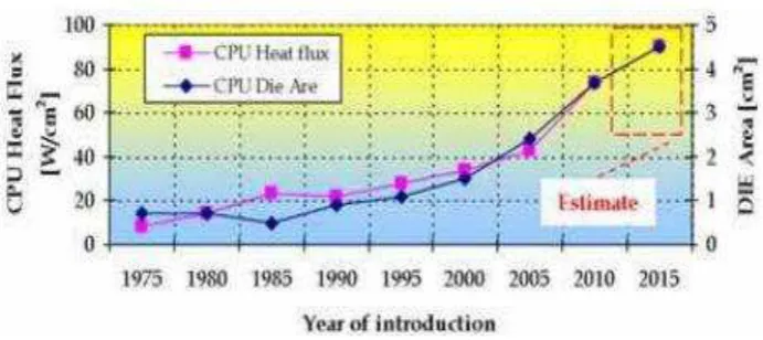
processing unit (CPU) rises (Mohan & Govindarajan, 2010). Based on Figure 1.1,
the density of thermal flow is highly needed to concern, no matter what is the
manufactured CPU (Mihai, 2007). The high temperature of CPU seriously increases
its failure mode and also shortens its own life (Mohan & Govindarajan, 2010).
INTRODUCTION
2 Figure 1.1: Thermal Flow Variation and CPU die size depending the production year (Mihai, 2007)
In order to ensure the device operates within safe temperature condition, heat sink a structural device used removes heat from a functional electronic package to the
surrounding is required (Ekpu et al., 2011). Various heat sink design options have been developed to offer efficient and economical solutions over the years (Eppes et
al., 2012). According to Huang & Chang (2012), there are a vast researchers has
been seen that a heat sink with excellent geometrical design will provide higher
efficiency and better cooling performance. A good design of heat sink should comply
with the related standards, and has good reliability and durability, manufacturability,
reasonable cost and etc., so that to meet the desired temperatures under the worst
working condition (Liu et al., 2012).
For the production of heat sinks, thermal management materials such as aluminium
are commonly used because they exhibit high thermal conductivity and reasonably
low coefficient of thermal expansion properties. Lower density thermal management
materials are preferred due to miniaturization of electronic devices at present (Ekpu
et al., 2011). Aluminium air-cooled heat sink has becomes one of the most
commonly used devices to cool CPUs because it leads to the advantageous of simple
maintenance process, more reliability, lower manufacturing cost, and no
environmental concerns. According to Das (2006), recycling aluminium alloys are
provided major economic benefits. Therefore, the aluminium alloy is definitely an
appropriate material for heat sink in considering the perspective of sustainable
3 This paper focuses on three types of fin designs such as plate finned heat sink, in-line
strip finned heat sink, and splayed pin finned heat sink, which are the common types
used in the computer for CPU cooling. 3D SolidWorks models for the three fin
designs are presented and temperature distribution and total heat flux are predicted
for the heat sinks in a range of temperature using finite element analysis which is
implemented using ANSYS software. This project is proposed an improved design of
finned heat sink and it is compared to the other finned heat sink. Therefore, a fin
design which has the most excellent in thermal performance is obtained at the end of
this project. The aluminium alloy 6063 is used as material of fins, but the addition of
other metals in the amounts commonly used in aluminium alloys does not
appreciably change the density (EAA, 1994).
1.2 Problem Statement
Computers continue to get faster via smaller and more intricate circuitry, which
generates mass amounts of heat. Heat given off by processors must be dissipated to
prevent the electrical equipments operate slowly or malfunction. According to
Gurrum et al. (2004), heat dissipation rates for computer CPUs may increase as high
as 180 W for the next few years and as high as 288 W by the year 2016.
The finned heat sinks work under uncertainty conditions with fluctuated temperature
and heat capacity. Electrical equipments will failure in operation as the heat transfer
rate of finned heat sinks is much lower compared to the total heat released from CPU.
This had become the main problem which arises in designing fins with a desired
material. Therefore, thermal analysis on the fin designs are required to test the
thermal performance of fins under certain range of ambient temperature, as well as
the factor of safety and fin efficiency are analyzed under steady state and transient
condition respectively.
In addition to the present world, sustainable development of the environment has
become the pivotal political and social issue to solve the problems of destruction the
4 be a critical part, but the integration of appropriate material with the fin designs and
analyzed under uncertainty heat capacity has becomes more challenging. Therefore,
a high thermal conductivity material is required so the fins can resist under any
temperature.
1.3 Objectives
The objectives of this project are
a) To investigate the design parameters of fins.
b) To analyze the uncertainty heat capacity for fins using engineering analysis
software.
c) To design of fins under uncertainty heat capacity.
1.4 Scope of Project
This project focuses the design of finned heat sink used in the cooling of central
processing unit (CPU) for computer. There are many different designs of finned heat
sink commercially available in the market, but only three existing designs which are
the heat sinks with plate fins, in-line strip fins, and splayed pin fins are investigated
under natural convection. Aluminium alloy 6063-O is used as the only and desirable
material for the three fin designs for further simulation and analysis.
The performance of a heat sink is affected by various parameters such as fin shapes,
fin arrangement or alignment; base length (L), fin height (H), fin thickness (t), sink
width (W), fin spacing (s), base thickness (h), fin length (w) and number of fins (n)
which all are measured in unit of millimeter (mm). These parameters can considered
as the performance improvement paths for the selected heat sinks. Many design
constraints such as heat transfer surface area (A), heat transfer coefficient (h), ambient
5
explored and attention is focused on the selection of fin designs under uncertainty heat
capacity.
Three dimensional (3D) fin design models are generated using SolidWorks 2010
software and the simulations are conducted with the aids of ANSYS software.
Thermal analysis is conducted respectively under steady state condition and transient
condition that involves conduction and convection phenomena.
Thermal analysis of the three fin models was first conducted under steady state
condition at different ambient temperature to analyze the temperature distribution,
total heat flux, and factor of safety of finned heat sink. The results from the
simulations are analyzed and discussed; therefore, the best among the three fin
models can be selected by weighted scoring method. Besides, an improved design of
finned heat sink is proposed based on the comparison of the candidate fin models.
The selected fin design and proposed fin design are then analyzed under transient
condition. This analysis is required to predict the temperature distribution and total
heat flux of the heat sink body which are vary with time. The results of simulation
for both fin models are analyzed and compared so that a fin design with the best
thermal performance is selected at the end of this project.
1.5 Project Organization
This report is divided into five different chapters which are completed within the
duration of one year. These chapters are briefly introduced and described at below:
(a) Chapter 1 - Introduction
Chapter 1 proposes an overview for the entire project and shows the systematic
plan to conduct this project. This chapter involves the project background,
problem statements, objectives, scope of project, project organization. The Gantt
chart illustrates the activity planning of FYP I and FYP II is attached at Appendix
6 (b) Chapter 2 - Literature Review
Chapter 2 provides the explanations of fins used in the cooling of CPU in
computer, fin designs, design principles, heat capacity and the material used,
aluminium alloy 6063 is used for the fin designs. This chapter provides also the
reviews of the software, including SolidWorks 2010 and ANSYS software. The
information regarding to each element which includes introduction, properties,
and some applications are obtained from the past studies, journals, books and
articles to help in understanding more about the elements that involved in this
project and as the guidance for the project flow. Relevant methods used by other
researchers are reviewed and compared in order to act as guideline to solve the
problems and to achieve the objectives.
(c) Chapter 3 - Research Methodology
Chapter 3 is described the methodology used to solve the problems and to
achieve the objectives. A flow chart is generated with its descriptions to show the
process flow and methodology that used as a guideline for this project. In this
chapter, the relevant variables and elements are defined in detail together with the
engineering sketching of three different fin designs.
(d) Chapter 4 - Result and Discussion
Chapter 4 describes the implementation of the methodology which had proposed
in Chapter 3 to obtain three detail designs of fin and their accurate data through
the uses of design and analysis software. The results are then to be explained and
compared between each other using the relevant variables. The weighted scoring
method is implemented for the selection of design. Lastly, the best fin design is
selected based on the analysis and it is investigated and compared with proposed
design through simulation. Finally, only one with best performance is chosen.
(e) Chapter 5 - Conclusion
Chapter 5 is the last chapter which conclude the overall findings of the entire
project and the most excellent design of fins is obtained. This chapter provides