UNIVERSITI TEKNIKAL MALAYSIA MELAKA
PNEUMATIC DRIVEN 180 DEGREE ROTATION PICK AND
PLACE MECHANISM WITH CONVEYOR SYSTEM
This report submitted in accordance with requirement of the UniversitiTeknikal Malaysia Melaka (UTeM) for the Bachelor Degree of Engineering Technology
(Industrial Automation & Robotics) (Hons.)
by
FATIN SYAKIRA BINTI MOHD HASSAN B071210025
900921-04-5216
UNIVERSITI TEKNIKAL MALAYSIA MELAKA
BORANG PENGESAHAN STATUS LAPORAN PROJEK SARJANA MUDA
TAJUK: Pneumatic Driven 180 Degree Rotation Pick and Place Mechanism with Conveyor System
SESI PENGAJIAN: 2015/16 Semester 1
SayaFATIN SYAKIRA BINTI MOHD HASSAN
MengakumembenarkanLaporan PSM inidisimpan di PerpustakaanUniversitiTeknikal Malaysia Melaka (UTeM) dengansyarat-syaratkegunaansepertiberikut:
1. Laporan PSM adalah hak milik Universiti Teknikal Malaysia Melaka dan penulis. 2. Perpustakaan Universiti Teknikal Malaysia Melaka dibenarkan membuat salinan
untuk tujuan pengajian sahaja dengan izin penulis.
3. Perpustakaan dibenarkan membuat salinan laporan PSM ini sebagai bahan pertukaran antara institusi pengajian tinggi.
4. **Silatandakan ( ) sebagaimana yang termaktubdalam AKTA RAHSIA RASMI 1972)
No. 30, Jalan Seri Duyong 2/9,
Taman Seri DuyongSeksyen 2,
FAKULTI TEKNOLOGI KEJURUTERAAN
76100 Durian Tunggal, Melaka.
Tuan/Puan,
PENGKELASAN LAPORAN PSM SEBAGAI SULIT/TERHAD LAPORAN PROJEK SARJANA MUDA TEKNOLOGI KEJURUTERAAN PEMBUATAN (COURSE NAME): AAA BIN BBB
SukacitadimaklumkanbahawaLaporan PSM yang tersebut di
atasbertajuk“Quality and Performance Investigation of TiAlN Coated Drill Tools” mohondikelaskansebagai *SULIT / TERHAD untuktempohLIMA(5) tahundaritarikhsuratini.
2. Hal iniadalahkeranaIANYA MERUPAKAN PROJEK YANG DITAJA OLEH SYARIKAT LUAR DAN HASIL KAJIANNYA ADALAH SULIT.
Sekiandimaklumkan.Terimakasih.
Yang benar,
________________
Tandatangandan Cop Penyelia
* Potong yang tidakberkenaan
iii
DECLARATION
I hereby, declared this report entitled “Pneumatic Driven 180 Degree Rotation Pick
and Place Mechanism with Conveyor System” is the results of my own research
except as cited in references.
Signature :………
Name : FATIN SYAKIRA BINTI MOHD HASSAN
iv
APPROVAL
This report is submitted to the Faculty of Engineering Technology of UTeM as a partial fulfillment of the requirements for the degree of Bachelor of Engineering Technology (Type your department’s name here) (Hons.). The member of the supervisory is as follow:
v
ABSTRACT
vi manapenghasilanprojek yang melibatkanProgrammable Logic Control (PLC)yang merupakankomputer digital yang digunakanuntukautomasi yang direkauntukaturanpelbagai di manadalamprojekiniiaadalahuntuksusunan digital dan analog masukkandankeluaran, Graphic User Interface (GUI)yang membolehkanpenggunauntukberinteraksidenganperantielektronikmelaluiikongrafikd anpetunjuk visual, perkakasandanintegrasiperisian. Mekanismainidigunakanuntukmengangkatdanmeletakkanobjekmengikutpadaspesifik asi yang ditetapkan.Putaranmekanismainiadalah 180 darjah (arah jam) dan -180
darjah (arahlawan
vii
DEDICATIONS
viii
ACKNOWLEDGMENTS
I would like to thankmy advisor Mr.Maslan bin Zainon for the continuous support of my Bachelor Degree study and related research, for his patience, motivation, and immense knowledge. His guidance helped me in all the time of research and writing of this report. I could not have imagined having a better advisor and mentor for my Bachelor Degree study.
My sincere thanks also goes to my fellow lab mate in for the stimulating discussion, for the sleepless nights we were working together before deadlines, and for all the fun we had in the last four years.
ix
TABLE OF CONTENTS ... ix
LIST OF FIGURES ... xiii
LIST OF TABLE ... xv
CHAPTER 1 ... 1
1.0 Introduction ... 1
1.1 Background ... 1
1.2 Motivation of Research ... 2
1.3 Problem Statement ... 2
1.4 Problem Objectives ... 3
1.5 Project Scope ... 3
1.6 Report Outline ... 3
CHAPTER 2 ... 4
2.0 Introduction ... 4
x
Motion by Rosidah Sam, Kamarul Arrifin and Norlida Buniyamin ... 5
2.1.2 Pick and Place Robot by Mohammad Hafizuddin bin ahmad Sabri ... 6
2.1.3 Optimal Kinematic Design of a New 3-DOF Planar Manipulator for Pick and Place Application by Bin Liao Yunkiang Lou ... 7
2.1.4 Multisensor Controlled Robotic Tracking and Automatic Pick and Place by Ilhan Konukseven, Bilgin Kaftanoglu and Tuna Balkan ... 7
2.1.5 Modelling and Control of A Joint Driven by Pneumatic Actuator by Nonutaka Tsujiuchi, Takayuki Koizumi, Hiroto kan, Hiroyuki Takeda, Tatsuwo Kudawara and Masanori Hirano ... 8
2.1.6 Design of a Servo Driven, Adjustable Pick and Place Mechanism by Owen Butler, Buddhi Paranamana, William Powers and Arvind Srinivasan ... 9
2.1.7 Development of Robot Hand with Pneumatic Actuator and Construct of Master-Slave System by Shinya Nishino, Takayuki Koizumi, hiroyuki Komatsubara, Tatuwo Kudawara and Mikio Shimizu ... 10
2.1.8 Automatic Planning of Pick and Place Operation in Presence of Uncertainties by I. Mason, R. Alami and P. Violero ... 10
2.1.9 Pick and Place Hand Mechanism without Any Actuator and Sensors by Satoru Sakai, Yasuhide Nakamura and Kenzo Nonami ... 11
CHAPTER 3 ... 12
3.0 Introduction ... 12
3.1 Project Methodology ... 13
3.2 Methodology Flowchart ... 15
3.3 Software Flowchart ... 16
3.3.1 Software Overview... 17
xi
3.3.1.2 Graphical User Interface (GUI) ... 19
3.4 Hardware Flowchart ... 21
3.4.1 Hardware Overview ... 22
3.4.1.1 Servo Motor ... 22
3.4.2 DC Geared Motor ... 23
3.4.2.1 Conveyor ... 24
3.4.2.2 Pneumatic Cylinder... 24
3.4.2.3 Solenoid Valve ... 27
3.4.2.4 Infrared Sensor ... 27
3.4.2.5 End Effector ... 28
3.4.2.6 Limit Switch ... 28
CHAPTER 4 ... 30
4.0 Introduction ... 30
4.1 Progress of Final Year Project (FYP) 2 ... 30
4.2 Results ... 31
4.2.1 Ladder Diagram of the PLC ... 31
4.2.2 SolidWork 3D CAD of Mechanism ... 33
4.2.3 Mechanism Develop... 35
4.2.4 Graphical user Interface (GUI) ... 37
4.3 Analysis ... 39
4.3.1 Forward Kinematics Analysis ... 40
4.3.2 Reverse Kinematics Analysis ... 41
xii
5.1 Achievement of Research Objectives ... 43
5.2 Significance of Research ... 44
5.3 Problems Faced During Research ... 44
5.4 Suggestion for Future Work ... 44
REFERENCES ... 45
xiii
LIST OF FIGURES
Figure 2.1: Component of Robot 1 and 2 ... 5
Figure 2.2: Assembly of Robot 1 and 2 ... 6
Figure 2.3: Image area and work area of the robot ... 8
Figure 2.4: Schematic of 1-Link Arm ... 9
Figure 2.5: Experimental Setup ... 11
Figure 3.1: Object Oriented Development Life Cycle ... 13
Figure 3.2: Methodology Flow Chart ... 15
Figure 3.3: Software Flow Chart ... 16
Figure 3.4: What is inside PLC ... 17
Figure 3.5: System Operation Flow Chart ... 18
Figure 3.6: A Block Diagram of Human Machine Interface (HMI) ... 19
Figure 3.7:HMI TouchWin TG465-MT Touch Screen Panel ... 19
Figure 3.8: TouchWin TG465-MT linked to PLC ... 20
Figure 3.9: Hardware Flow Chart ... 21
Figure 3.10: Pulse Width Modulation (PWM) ... 22
Figure 3.11: TowerPro MG995 Metal Gear Servo ... 22
Figure 3.12: DC Geared Motor ... 23
Figure 3.13: Horizontal Type of Conveyor ... 24
Figure 3.14: Double Acting Cylinder... 25
Figure 3.15: Pneumatic Flow Chart ... 26
Figure 3.16: Solenoid Valve (5/2 Way) ... 27
Figure 3.17: Adjustable IR Reflection Sensor ... 27
Figure 3.18: End Effector ... 28
Figure 3.19: Limit Switch ... 28
Figure 4.1: Ladder Diagram (to be continued)... 31
Figure 4.2: Pneumatic Driven 180 Degree Rotation Pick and Place Mechanism with Conveyor System Top View ... 33
Figure 4.3: Pneumatic Driven 180 Degree Rotation Pick and Place Mechanism with Conveyor System Front View ... 34
Figure 4.4: Pneumatic Driven 180 Degree Rotation Pick and Place Mechanism with Conveyor SystemSide View ... 34
Figure 4.5: Overview for the Pneumatic Driven 180 Degree Rotation Pick and Place Mechanism with Conveyor System ... 35
Figure 4.6: Pneumatic Driven 180 Degree Rotation Pick and Place Mechanism with Conveyor System Top View (real product) ... 35
Figure 4.7: Pneumatic Driven 180 Degree Rotation Pick and Place Mechanism with Conveyor System Front View (real product) ... 36
xiv
xv
LIST OF TABLE
1
CHAPTER 1
INTRODUCTION
1.0 Introduction
Robotics technology has been researched and applicable in the industrial where it has reached to a matured point. Robots are used to replace people especially in the production line and suitable for repetitive work. The main aim of this project is to develop an arm mechanism which could be used as a powerful pick and place which is called as gantry robot. The design of this mechanism is with base rotation and wrist motion with a functional gripper to hold object. This project includes a PLC which used to drive the motor according to the inputs and gear motor to control the rotation of the mechanism.
1.1 Background
2
Based on the research carried out by the International Federation of Robotics (IFR), there are top 8 reasons why robot is used in the industries:
(a) Increase production output rates (b) Reduce operating costs
(c) Improve process quality
(d) Improve workplace health & safety (e) Increase product manufacturing flexibility (f) Reduce material waste and increase yield (g) Save space in high value manufacturing areas (h) Reduce capital costs (inventory, work in progress)
1.2 Motivation of Research
The motivation is to focus on the design and development of pneumatic driven 180 degree rotation pick and place mechanism with conveyor system. The development project will involve Programmable Logic Controller (PLC) which act as the brain of the mechanism and perform work automatically with minimum supervision or intervention, Graphical User interface (GUI) development that shows the motion of the system, hardware and software integration as well as system troubleshooting.
1.3 Problem Statement
3
The objectives of the project include to demonstrate the concept of how pick and place mechanism function and operate and to design and develop the hardware for pick and place mechanism with conveyor system and the combination of pneumatic and motion system using the software of Programmable Logic Controller (PLC) and Graphical User Interface (GUI).
1.5 Project Scope
There are two scopes are needed to be done to fulfill the requirement of this project which are to design a program that controls the movement of pick and place and to design and fabricate the mechanical structure for the Pneumatic Driven 180 Degree Rotation Pick and Place Mechanism with Conveyor System.
1.6 Report Outline
This report is divided into five chapters. Chapter 1 is the introduction of the project which explains the background of the project, problem statement, project objectives and the scope of the project. Chapter 2 is the literature reviews of the project which highlights the references and understanding gained from various sources such include popular periodicals, books on specific subject, reviews of research and journals. These materials are used to support the development of this project.
4
CHAPTER 2
LITERATURE REVIEW
2.0 Introduction
This chapter will discuss mainly on the reference and understanding which is gained from various source such as books, journals, internet and previous projects. These are the materials used as the main source for this entire project by identifying the relevance of the research.
The core focus in this literature is about how a pick and place mechanism operated with different kind of method applied on the mechanism and the characteristic of the pick and place mechanism.
2.1 Journals
5
Soft Motion by Rosidah Sam, KamarulArrifin and NorlidaBuniyamin
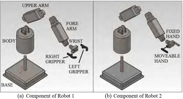
This paper is prepared based on the design of pick and place robotics system using Solidwork 3D CAD software where it is used to design a Cartesian robot and articulated industrial robotic arm with different end-effectors [1]. It is designed to shorten the robot development time and to improve the quality and speed of the designed robot. After assembled and simulation was made on the arm robot, it is presented to demonstrate the pick and place system which is proven that by using Solidworks software, it enable the user to design a robotic and assemble it to demonstrate the motion of the system made and also convenient for troubleshooting.
(a) Component of Robot 1 (b) Component of Robot 2
6
(a) Assembly of Robot 1 (b) Assembly of Robot 2
Figure 2.1 shows the parts on the robot 1 and 2. The different between robots 1 and 2 is the end-effectors such as robot 1 has the left gripper and robot 2 is using moveable hand. The parts of the two robots are then assembled by using mate function in the Solidwork software as shown in the Figure 2.2.
2.1.2 Pick and Place Robot by Mohammad Hafizuddin bin ahmadSabri
This project [2] is designed to facile the sorting process of heavy materials which requires high amount of repetitive motion. This robot is a basic development for that type of robot where it used Programmable Logic Control (PLC) to control the operation of the robot. It can be rotate 90 degree (clockwise) and -90 degree (counter clockwise). The arm is designed to move horizontally to pick the object without gripping it and place the object on the other side. With this robot, efficiency of the work is increased thus prevent injuries to the manpower plus inexpensive construction cost.
7
for Pick and Place Application by Bin Liao Yunkiang Lou
This paper provides an optimal kinematic design of a new 3-DOF planar parallel manipulator for pick-and-place application [3]. The researchers derived the loop-closure equations of the robot as the first step. Then, they discussed the kinematics and singularity analysis in order to use the index of the average inverse condition number. In this paper, it stated that velocities are the important element in kinematic for the pick-and-place applications. A new manipulator named V3 is co-axis actuated arrangement with three sub chains in parallel planes. As the result, an optimal design of manipulator has been design has made which can be operated under high speed.
2.1.4 Multisensor Controlled Robotic Tracking and Automatic Pick and Place by IlhanKonukseven, BilginKaftanoglu and Tuna Balkan
8
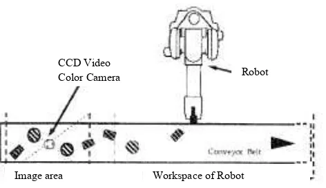
Figure 2.3: Image area and work area of the robot
Figure 2.3 shows the analysis of motion where each frame of the sequence is segmented. The objects are placed randomly on the conveyor belt and the frame-object list is used to store the parameters of the frame-object. Sensor-based system is produced to provide information for the robotic tracking control. The motion of the end-effector is controlled by an end–effector based infrared proximity sensors and conveyor position encoder in order for the grasping system to operate.
2.1.5 Modelling and Control of A Joint Driven by Pneumatic Actuator by NonutakaTsujiuchi, Takayuki Koizumi, Hirotokan, Hiroyuki Takeda, TatsuwoKudawara and Masanori Hirano
This research is based on the focused of robot that has been used widely in the industries and perform flexible as people [5]. However, the robot needs to features safety precaution in order not to injure people. With that, the researchers had come out with the development of robot hand that can use as artificial muscle-type pneumatic actuators which functioned like human hand. In addition, big compressor is needed when a pneumatic actuator is used. To overcome this problem, they developed a low-pressure, low volume pneumatic actuator to drive and enable the robot hand perform flexibly and safely which is assume to have contact with people. PID control system is constructed in order to simulate a 1-link arm that has one degree of freedom.
Robot CCD Video
Color Camera