accredited by DGHE (DIKTI), Decree No: 51/Dikti/Kep/2010 65
Power Oscillation Damping Control using Robust
Coordinated Smart Devices
Tumiran1, Cuk Supriyadi Ali Nandar*2, Sarjiya3
1,3
Department of Electrical Engineering and Information Technology, Gadjah Mada University (UGM) Jl. Grafika no.2 Kampus UGM, Yogyakarta 55281
2
Badan Pengkajian dan Penerapan Teknologi (BPPT) Jl. MH Thamrin No.8 Jakarta Pusat
e-mail: [email protected], [email protected]*2
Abstrak
Sistem interkoneksi tenaga listrik dengan daya damping yang rendah dapat menjadi penyebab terjadinya masalah osilasi frekuensi rendah pada sistem tenaga listrik. Pada kondisi kerja yang ekstrim, stabilitas sistem daya (PSS) bisa mengalami kegagalan dalam meredam osilasi tersebut. Makalah ini menyajikan desain kendali robust pada PSS dan kapasitor seri terkendali thyristor (TCSC) secara simultan untuk meredam osilasi pada sistem interkoneksi tenaga listrik. Untuk menggaransi kendali yang kokoh, teknik pertubasi aditif invers digunakan untuk merepresentasikan ketidakpastian sistem pada sistem tenaga listrik seperti perubahan parameter sistem, pembangkitan sistem dan kondisi pembebanan yang sulit diprediksi secara pasti. Pada studi ini, algoritma genetika digunakan untuk menala parameter kendali pada PSS dan TCSC secara simultan. Studi simulasi telah dilakukan pada sistem bus tak berhingga mesin tunggal (SMIB) untuk membuktikan bahwa kendali yang telah didesain mempunyai unjuk kerja dan kekokohan yang lebih bagus dibandingkan dengan kendali konvensional.
Kata kunci: algoritma genetika, kendali kokoh, pertubasi aditif invers, PSS, TCSC
Abstract
The lack of damping of the electromechanical oscillation modes usually causes severe problems of low frequency oscillations in interconnected power systems. In the extreme operating conditions, PSS may fail to damp power oscillation. This paper presents a robust coordinated design of power system stabilizer (PSS) and thyristor controlled series capacitor (TCSC) to damp power oscillation in an interconnected power system. The inverse additive perturbation is applied to represent unstructured uncertainties in the power system such as variations of system parameters, system generating and loading conditions. In addition, genetic algorithm is employed to search a robust tuning to the controller parameters of both PSS and TCSC simultaneously. Simulation studies have been done in a single machine infinite bus system to confirm that the performance and robustness of the proposed controller are superior to that of the conventional controller.
Keywords: genetic algorithm, inverse additive perturbation, PSS, robust control, TCSC
1. Introduction
Power system black out due to low frequency oscillation becomes serious problem in the power system. To prevent this problem, the application of smart technology such as PSS and flexible alternating current transmission systems (FACTS) device to provide an additional damping of power system is highly needed. At present, power system stabilizer(PSS) has been selected as a cost effective device to damp power oscillation via the excitation system [1]. Several approaches based on modern control theories have been successfully applied to design PSSs, such as eigenvalue assignment [2, 3], and linear quadratic regulator [4]. These works have confirmed the significant performance of PSS. However, PSS may suffer a drawback of being liable to cause great variations in the voltage profile and they may even result in leading power factor operation and losing system stability under severe disturbances [5].
been observed [6]. In this study, TCSC is installed in the power system to tackle the limitation of PSS. Several previous works has paid attentions to tuning conventional lead/lag PSS and TCSC parameters simultaneously by heuristic methods such as simulated simulated annealing [7] and genetic algorithm [8]. In these studies, however, the uncertainty model is not embedded in the mathematical model of the power system. Therefore, the robust stability margin of the system in these works may not be guaranteed in the face of several uncertainties.
To get the robust controller, H∞ control has been applied to design of a robust PSS configuration [9]. In this work, the designed H∞ PSS via mixed sensitivity approach have confirmed the significant performance and high robustness. In this approach, however, due to the trade-off relation between sensitivity function and complementary sensitivity function, the weighting functions in H∞ control design cannot be selected easily. Moreover, the structure of conventional H∞controller is high order and complex which is different from the conventional PI or lead/lag controller. Despite the significant potential of control techniques mentioned above, power system utilities still prefer the conventional low order PI or lead/lag controller. This is due to the ease of implementation, the long-term reliability, etc.
This paper proposes the robust coordinated PSS and TCSC to damp low frequency oscillation in an interconnected power system. To take system uncertainties into account in the control design, an inverse additive perturbation [10] is applied to represent all unstructured uncertainties in the system modeling. Moreover, the performance conditions in the damping ratio and the real part of the dominant mode is applied to formulate the optimization problem. In this work, the structure of the both proposed controller of PSS and TCSC are the first-order lead/lag compensator. It is easy to implement in the real system. To achieve the controller parameters, the genetic algorithm (GA) is used to solve the optimization problem. Simulation studies explicitly show that the proposed robust PSS and TCSC are very robust to various system uncertainties in comparison to that of conventional controller [3,7].
This paper is organized as follows. First, power system modeling is explained in section 2. Section 3 presents the proposed design method for optimization of coordinated robust PSS and TCSC parameters using GA. Subsequently, section 4 shows the results and analysis. Finally, the conclusion is given.
2. A Robust Tuning to the Controller Parameters 2.1 Power System Modeling
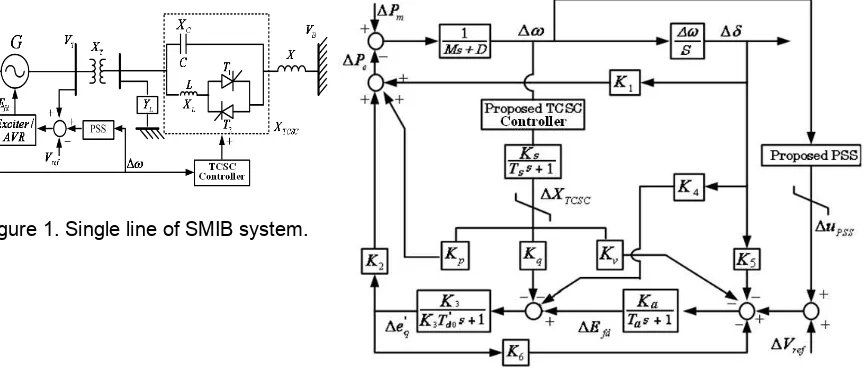
A single machine infinite bus (SMIB) system shown in Figure 1 is used to explain the design of proposed robust coordinated PSS and TCSC. The linearized forth-order model of SMIB system [1] for robust PSS and TCSC design is depicted in Figure 2. System parameters and notations are given in [7]. The initial condition used as the design condition of the proposed PSS is Pe = 1.0 p.u., Qe= 0.015 p.u.
Figure 1. Single line of SMIB system.
The linearized system in Figure 2 can be writen as
In short, the state equation of system can be expressed as
u
Δ are the control output signal of the PSS and TCSC, which uses only the angular velocity deviation (
Δ
ω
) as a feedback input signal.2.2 Configuration of PSS and TCSC Controller
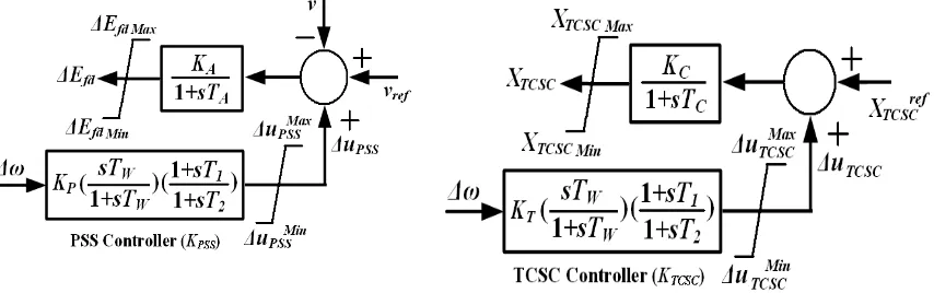
As shown in Figure 3, the PSS controller (KPSS) is represented by a simple 1st order lead/lag controller and wash out which uses system frequency deviation (∆ω) as a feedback input signal. The power system stabilizer (PSS) is used to provide the additional damping via the excitation system. Moreover, the TCSC block diagram is depicted in Figure 4. The TCSC diagram consists of two transfer functions, i.e. the TCSC model and the lead/lag based power oscillation controller. Based on [7], the TCSC can be modeled by the first-order transfer function with time constant TC = 0.05 sec. In this work, TCSC controller is presented by practically a 1st order lead/lag controller and wash out with single feedback input signal, system frequency deviation (∆ω). Note that the system in equation (2) is a multi-input single-output (MISO) system. Here, the proposed design approach is applied to design a robust coordinated PSS controller (KPSS) and TCSC controller (KTCSC) simultaneously.
Figure 3. Block diagram of PSS controller
3. Reseach Method
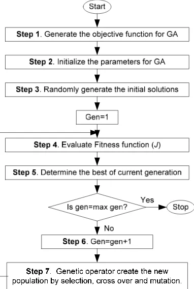
In this section, GA is applied to search the controller parameters with off line tuning. The flow chart of proposed control design is shown in Figure 5. Each step proposed method is explained as follows.
Figure 5. Flow chart of the proposed design
Figure 6. Feedback system with inverse additive perturbation
Figure 7. D-shape region in the s-plane
Step 1 Generate the objective function for GA optimization.
In this study, the performance and robust stability conditions in the inverse additive perturbation design approach is adopted to design a both robust PSS and TCSC. The conventional PSS and TCSC controller with a 1st -order lead/lag controller are represented by
ω Δ ⎟⎟ ⎠ ⎞ ⎜⎜
⎝ ⎛
+ + ⎟⎟ ⎠ ⎞ ⎜⎜
⎝ ⎛
+ =
Δ
1 1 1 2
1
sT sT sT
sT K u
W W P
PSS (5)
ω Δ ⎟⎟ ⎠ ⎞ ⎜⎜
⎝ ⎛
+ + ⎟⎟ ⎠ ⎞ ⎜⎜
⎝ ⎛
+ =
Δ
1 1 1 2
1
sT sT sT
sT K u
W W T
TCSC (6)
where, ΔuPSS , ΔuTCSC and Δω are the control output signal and the rotor speed deviation at both of PSS and TCSC, respectively; KPand KT are a controller gain of PSS and TCSC, respectively; TW is a wash-out time constant (s): and T1 andT2are time constants (s).
In this paper, the control parametersK, T1andT2are optimized by GA based on the following concept. As shown in Figure 6, the system with inverse additive perturbation [10] is applied to take the robust stability against uncertainties into account. For a stable additive uncertaintyΔA, the closed loop system is robust if the controller K stabilizes the nominal plant G. Based on the small gain theorem, the system is stable if
(
1)
1/ − <
Then
(
1)
1/ − <
ΔA ∞ G GK ∞ (8)
This yield
(
)
∞∞ < −
ΔA 1/G/1 GK (9)
The right hand side of equation (9) implies the maximum robust stability margin against inverse additive perturbation. Then, the robust stability margin of the closed loop system can be guaranteed in terms of the additive stability margin (ASM) as,
∞ −
<
)) ( ) ( 1 /( ) (
1 s K s G s
G
ASM (10)
By minimizing G (1−G K)∞, the robust stability margin of the closed-loop system is a
near optimum. In this study, the problem constraints are the controller parameters bounds. In addition to enhance the robust stability, another objective is to increase the damping ratio and place the closed-loop eigenvalues of hybrid wind-diesel power system in a D-shape region [11]. The conditions will place the system closed-loop eigenvalues in the D-shape region characterized by ζ ≥ζspecand σ≤σspecas shown in Figure 7.
Therefore, the design problem can be formulated as the following optimization problem.
Minimize G
(
1−GK)
∞ (11)Subject to ζ ζ≥ spec, σ σ≥ spec
Kc,i,min ≤Kc,i≤Kc,i,max, Ti,min ≤Ti ≤Ti,max, i=1,2
Where
ζ
andζ
specare actual and desired damping ratio, respectively,σ
and σspec are actual and desired real part of the electromechanical mode, Kc,min and Kc,max are minimum and maximum gains of both PSS and TCSC, Ti,min and Ti,max are minimum and maximum timeconstants of PSS and TCSC. The optimization problem is solved by GA.
Step 2 Initialize the search parameters for GA. Define genetic parameters such as population size, crossover, mutation rate, and maximum generation.
Step 3 Randomly generate the initial solution.
Step 4 Evaluate objective function of each individual in equation (11).
Step 5 Select the best individual in the current generation. Check the maximum generation. Step 6 Increase the generation.
Step 7 While the current generation is less than the maximum generation, create new population using genetic operators and go to step 4. If the current generation is the maximum generation, then stop
4. Simulation Results and Analysis
In this section, simulation studies in a single machine connected to infinite bus are carried out. System parameters are given in [7]. In the optimization, the ranges of search parameters are set as follows: ζspec is desired damping ratio is set as 0.5, σspec is desired real
part is set as -0.2,
K
min and Kmax are minimum and maximum gains of both PSS and TCSCmaximum generation is 100. The optimization problem is solved by genetic algorithm [12]. As a result, the designed controllers which are referred as “RPSS and RTCSC” are given simultaneously as shown as follows
⎟
In simulation studies, the performance and robustness of the proposed controllers are compared with PSS [3] and PSS and TCSC [7], that is
PSS[3] :
Next, the performance and robustness of the RPSS and RTCSC is compared with PSS
and TCSC [7]. To evaluate the robustness of controllers, the value of ASM of PSS and TCSC [7] and RPSS and RTCSC are shown in Table 1.As shown in Table 1, the value of ASM in the case of RPSS and RTCSC is greater than that in the case of PSS and RTCSC [7]. It is indicate that the better robust stability margin of the closed loop system can be achieved by the proposed method
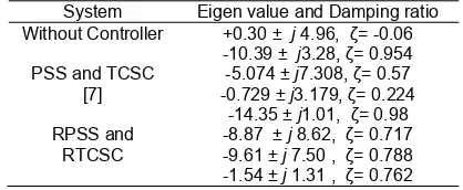
In addition, the eigenvalues corresponding to the electromechanical mode without controllers, PSS and RTCSC [7] and RPSS and RTCSC are listed in Table 2. Clearly, the damping ratio and real part of the oscillation mode are greatly enhanced with the proposed controller. On other hand, system without controller has negative damping or unstable.The limit on each PSS output (
Δ
u
PSS) and TCSC output (Δ
u
TCSC) is ±0.05 p.u. The system responses with controller are examined under three case studies as in Table 3.Table 1. Comparison of ASM
Controller ASM
PSS and TCSC [7] 0.6445
RPSS and RTCSC 8.0319
Table 2. Comparison of oscillation mode
System Eigen value and Damping ratio Without Controller +0.30 ± j 4.96, ζ= -0.06
Table 3. Operating condition
System
Case 1: Normal condition
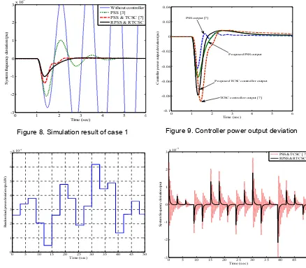
stabilize the power oscillation, the oscillation become higher and unstable. On other hand, PSS [3], PSS and TCSC [7] and proposed RPSSandRTCSC are able to damp power oscillations. However, the overshoot and setting time of power oscillation in case of RPSS and RTCSC is much lower than those of both PSS [3] and PSS and TCSC [7]. Next, to evaluate power capacities of both PSS and TCSC controller required for power oscillation stabilization. Figure 9 shows the controller output power deviation in case 1. Both controller power output of PSS and TCSC [7] and RPSS and RTCSC can properly remain within the allowable limits. However, the stabilizing effect of frequency oscillation by RPSS and RTCSC is superior to that of PSSandTCSC [7].
0 1 2 3 4 5 6 RPSS & RTCSC
Figure 8. Simulation result of case 1
0 1 2 3 4 5 6
TCSC controller output [7] Proposed TCSC controller output
Proposed PSS output PSS output [7]
Figure 9. Controller power output deviation
0 5 10 15 20 25 30 35 40 45 50
Figure 10. Random load power deviation
0 5 10 15 20 25 30 35 40 45 50
Figure 11. Simulation result of case 2
Case 2 : Light loading condition
In case 2, the random power input (ΔPm) as shown in Figure10 is injected to the system. The response of the system frequency deviation in case 2 is shown in Figure11, the damping effect of PSS and TCSC [7] is deteriorated. On the other hand, the frequency oscillations are effectively stabilized by RPSS and RTCSC. RPSS and RTCSC is rarely sensitive to the weak line condition.
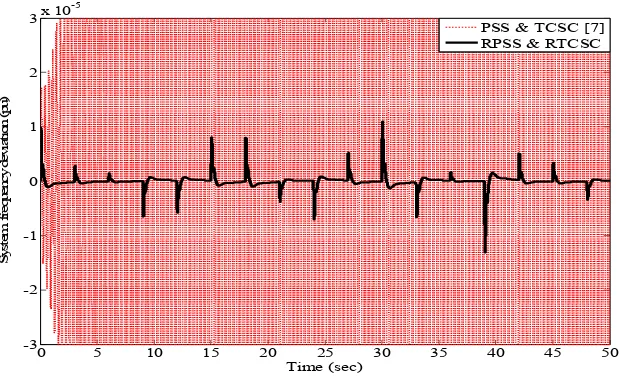
Case 3 : Heavy loading condition
contrast, the proposed RPSS and RTCSC can tolerate this situation. The frequency oscillation is significantly damped. These simulation results confirm that the proposed controller is very robust against various operating conditions.
0 5 10 15 20 25 30 35 40 45 50
-3 -2 -1 0 1 2
3x 10
-5
Time (sec)
S
ys
te
m
f
re
q
ue
nc
y
de
vi
a
ti
o
n (
p
u)
PSS & TCSC [7] RPSS & RTCSC
Figure 12. Simulation result of case 3
5. Conclusion
In this study, a robust design of coordinated PSS and TCSC has been proposed. The inverse additive perturbation is used to take the robust stability of the controlled power system against system uncertainties. The designed robust controllers are the conventional 1st order lead/lag compensator. Moreover, the controllers use only the speed deviation of generator as the feedback signal input. Therefore, the controllers are easy to realize in practical power system. The control effects and robustness of the proposed controller have been evaluated by various case studies. Simulation results confirm that the proposed controller is superior to the conventional controller in terms of the robustness against various uncertainties.
References
[1] Larsen E, Swarm D. Applying power system stabilizers. IEEE Transactions on Power Apparatus and Systems. 1981; 100(6): 3034-3046
[2] Gurrala G, Sen I. Power System Stabilizers Design for Interconnected Power Systems. IEEE Transactions on Power Systems. 2010; 25(2): 1042-1051.
[3] Abido MA. A novel approach to conventional power system stabilizer design using tabu search.
International Journal of Electrical Power and Energy System. 1999; 21(6): 443–454.
[4] Gupta R, Bandyopadhyay B, Kulkarni AM. Power system stabiliser for multimachine power system using robust decentralised periodic output feedback. IEE Proceedings - Control Theory & Applications. 2005; 152(1): 3-8.
[5] Rahim A, Nassimi S. Synchronous generator damping enhancement through coordinated control of exciter and SVC. IEE Proceeding on Generation, Transmission & Distribution. 1996; 143(2): 211–218. [6] Zarghami M, Crow ML, Jagannathan S. Nonlinear Control of FACTS Controllers for Damping
Interarea Oscillations in Power Systems. IEEE Trans. on Power Delivery. 2010; 25(4): 3113-3121. [7] Abido M.A. Pole placement technique for PSS and TCSC-based stabilizer design using simulated
annealing. Transactions on Electrical power and energy systems. 2000; 22: 543-554.
[8] Abdel-magid YL, Abido MA. Robust coordinated design of excitation and TCSC-based stabilizer using genetic algorithms. Transactions on Electrical power and energy systems. 2004; 69(2): 129-141. [9] Yan TC. Applying Optimisation Method to Power System Stabiliser Design-Parts 1 and 2.
Transactions on Electrical Power and Energy System. (1997); 19: 29-43.
[10] Gu P, Petkov Hr, Konstantinov MM. Robust control design with MATLAB. London: Springer. 2005. [11] Rashidi M, Rashidi F, Monavar H. Tuning of power system stabilizers via genetic algorithm for
stabilization of power system. IEEE International Conference on Systems, Man and Cybernetics. Iran. 2003; 5: 4649-4654.