DOI: 10.12928/TELKOMNIKA.v14i1.2030 262
Fluid Structure Interaction Numerical Simulation of
Wiresweep in Electronics Packaging
Dadan Ramdan*, Usman Harahap, Andi Rubiantara, Chu Yee Khor
Fakultas Teknik, Universitas Medan Area, Jl. Kolam No. 1 Medan Estate, Medan 20371 Faculty of Engineering Technology, Universiti Malaysia Perlis (UniMAP), Kampus Uni CITI Alam, Sungai Chuchuh, Padang Besar, 02100 Perlis, Malaysia. School of Mechanical Engineering, Universiti Sains Malaysia, Engineering Campus,
14300 Nibong Tebal, Penang, Malaysia” *Corresponding author, email: [email protected]
Abstract
This paper presents the computational of two-way fluid structure interaction technique by using Mesh based Parallel Code Coupling Interface for the visualization of wiresweep in the electronics packaging. Polymer rheology models with Castro-Macosko model have been used in the fluid flow model and Volume of Fluid technique was applied to melt front tracking of the fluid. The numerical analysis used User-Defined Function to allow curing kinetic model. Wiresweep profiles and pressure distribution within the mold are presented. The numerical results of melt front patterns and filled volume were compared with the previous experimental results and found in good agreement.
Keywords: Fluid Structure Interaction, MpCCI, Castro-Macosco model, Epoxy Molding Compound, Volume of Fluid, Wire Sweep.
Copyright © 2016 Universitas Ahmad Dahlan. All rights reserved.
1. Introduction
Nowadays, the electronics industry could offer their product in a compact size but also give more functionality, better performance and lower cost. It is widely used in applications including computing, communications, biomedical, automotive, military, and aerospace [1]. The exposure to moisture and mechanical stresses in varying temperature and humidity environments can be highly detrimental to electronic devices, which may lead to device failures. Therefore, several encapsulation methods had been employed to protect the device from mechanical and chemical hazards, and thermal path for heat dissipation. Besides, it is essential that the electronic devices be packaged for protection from their intended environment. The design, fabrication and encapsulation of the package has become increasingly complex and challenging owing to increased number of components and performance for miniaturization and aimed at lowering costs [2-4]. Thus, it may lead to the unintended features or defects during the encapsulation process, such as wire sweep.
Generally, wire bonding is the one of the principal ways to connect the silicon chip to the leadframe in the IC (Integrated Circuit) encapsulation process. Typically, the wire bonding process uses gold or aluminum wire to connect the die pads with the leadframe. Other packaging methods, such as flip chip, use tin-lead or lead free solder bump as an interconnection between the chip and substrates. The purpose of this process is to establish electrical interconnections for signal and power transfer. During the encapsulation process by using the transfer molding method, the fragile gold wire bonds are subjected to flow stresses from the molding compound [5, 6]. The flow stress induced from molding compound can cause the leadframe and the wire bond to permanently deform from their original geometry. The large displacement of a bonding wire can result in a package failure; either short circuits [3, 5-7], due to contact between adjacent wires or open circuit due to a broken wire [6]. Wire deformation can deteriorate electrical connection [5] even if the displacement is not so severe. It also affects the mechanical performance of the device, which will shorten its lifetime. Hence, it is crucial to minimize the wire-sweep deformation during the encapsulation process.
Several factors such as high resin viscosity [3, 8], high velocity [5, 6], unbalanced flows in the cavities cause paddle or lead frame movement [5], loop profile (bond height, bon span) [3-5], [7], [9-10], wire density [6-8], [11], wire diameter and mechanical properties [7] should be concerned during the encapsulation process. In the industry, to minimize the wire sweep always involves modification of physical design (i.e., leadframe, mold, and device layout), selection of molding compound and process parameter control based on experience and trial-and-error. These are costly and time-consuming practices. Therefore, the computational simulation method is essential, which could effectively resolve and minimize the problem [12] of wire sweep.
Some studies had been conducted to predict and improve the wire deformation during the molding process in a few years ago using software without considering online and real-time simulation for both fluid and solid analysis; and so far, the use of MpCCI code coupling is still lacking in wire deformation analysis. Yang et al. [13] developed two-way coupling computational technique between the separately computed flow and structural solution by using SIMPLEC algorithm. The two-way coupling between the flow field solution and the structural dynamic solution established by applying the equal and opposite load imposed by the fluid on the beam, and by the beam on the fluid. The case studied here represents a 12-leaded TO-220 component with a heat spreader. S. Yigit et al. [14] investigated the efficiency and accuracy of grid movement methods for a typical fluid-structure interaction configuration, which used FASTES for finite-volume flow solver, and FEAP for finite-element structural solver and the coupling interface MpCCI. The evaluation of efficiency and accuracy is based on computation times, number of coupling steps, structural displacements and swiveling frequencies. This method applied to a thin elastic structure, including one rotational degree of freedom fixed in a laminar channel flow.
Numerical simulation of fluid-structure interaction problem using MpCCI has been reported by F. Thiriafai and P. Geuzaine [15], who developed a computationally efficient methodology for the simulation of nonlinear FSI problem in order to perform aeroelastic simulations. B. Gatzhammer et al. [16] presented the coupling environment precise code interaction-coupling environment, which provides a black box solution for surface coupling to the tasks, mentioned before and serves as a basis for the development of new coupling features. This report showed FSI scenarios simulated with fixed-grid fluid solver. Basic idea, implementation details and application of MpCCI as a tool for the coupling of different simulation codes were reported by W.Joppich et al. [17] and A. Scheiber[18]. They described that, the main goal of MpCCI is to deliver a library that is easy to use for more or less loosely coupled simulation code. The program is executable and integrated into a new program with each of the original main programs then used as a subroutine. In recent years, the wire sweep analysis in the transfer molding and compression molding was reported by Han and Costa [19] based on the industrial case. Besides, Ali et al. [20] investigated the wire sweep characteristics on various wire locations, mold flow direction, wire length, wire pitches and wire angles on Low Quad Flat Packages (LQFP). They found that wires around the corner region exhibited higher wire sweep percentage.
2. Mathematical Model 2.1. Fluid Analysis
In the simulation model, the encapsulation material and air are assumed incompressible. The governing equations describing the fluid flow are conservation of mass, conservation of momentum and conservation of mass, conservation of momentum and conservation of energy. FLUENT normally solves the governing equations using Cartesian spatial coordinates and velocity components [2].
The molding compound was assumed to be a generalized Newtonian fluid (GNF). Several models have been used to predict the relationship between viscosity and the degree of polymerization. The Castro–Macosko model has been applied by W.R Jong et al. [11], Nguyen et al. [23] and is selected to use in this simulation. Table 1 summarized the material properties of the EMC considered in the current simulation.
The basic idea of the VOF scheme is to locate and evolve the distribution of, say, the liquid phase by assigning for each cell in the computational grid a scalar, F, which specifies the fraction of the cell's volume occupied by liquid. Thus, F takes the value of 1 (F=1) in the cell, which contains only resin, the value 0 (F=0) in cells which are void of resin, and a value between 0 and 1 (0<F<1) in “interface” cells or referred as the resin melt front. The equation of melt front over time is governed by the following transport equation:
∙ 0 (1)
Table 1. Material properties of EMC used in the mold filling analysis [24]
Parameter Value Unit
To calculate the drag force exerted on the wires by the resin flow, the value of velocities and viscosities have to be determined from the mold filling simulation. Then, the Lamb’s model is utilized to calculate the drag force as follows [6, 8 and 24]:
(2)
Where D is the drag force per unit length, ρ is the fluid density, U is the undistributed upstream velocity, d is the wire diameter and CD is the drag coefficient, which can be written as:
. (3)
(4)
where η is the fluid viscosity.
In order to assist the designer of a wire profile to obtain a reasonable allowed sweep, a sweep deflection model based on the contribution of the bending moment and the twisting moment has been proposed by Kung et al. [4]. According to the model, the sweep deflection of a wire bon δ can be written as:
∗ (5)
Where S is the length of the wire bond, fB is the bending geometry factor for the bending moment, fT is the twisting geometry factor for the twisting moment, H is the height of wire, L is the length of wire span, G is the shear modulus of wire, E is the elastic modulus of wire, I is the momentum of inertia of the wire, Ip is the polar momentum of inertia of the wire.
3. Numerical Simulation
3.1. Simulation Model and Boundary Conditions in FLUENT
The volume of fluid (VOF) model in FLUENT 6.3.26 is utilized to simulate the process [22-23]. In the VOF model, the fluids share a single set of momentum equations, and the volume fraction of each of the fluids in each computational cell is tracked throughout the domain [22]. Air and EMC are defined as the phases in the analysis. Implicit solution and time dependent formulation are applied for the volume fraction in every time step. The volume fraction of the encapsulation material is defined as one and zero value for air phase.
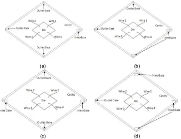
(a) (b)
(c) (d)
Figure 1. Mold cavity package model; (a) Three Outlet and one inlet gate, (b) Two outlet and two inlet gate cross, (c) Two outlet and two inlet gate diagonal and (d) One outlet and three inlet
Besides, viscosity Castro Macosko model and VOF techniques are applied to track the melt front. Castro Macosko viscosity model with curing effect was written into C language using Microsoft VISUAL Studio 2005 and compiled as UDF in FLUENT. The mold cavity package model used in the present study and its dimensions are shown in Figure 1. The dimension of the mold cavity is 100 mm ×100 mm × 4 mm, die is 30 mm × 30 mm and inlet is 8 mm × 8 mm [24]. The flow direction is diagonal of x and z direction to the undeformed wire axis and the properties are approximately the same as those used in ref. [24]. The model is created by using GAMBIT software and average 395.000 tetrahedral elements are generated for simulation (Figure 2) in terms of accuracy and computational cost. Besides, time step size is also tested and 0.001 s is found to be the optimum. The governing equations are discretized by the first order upwind scheme, and solve by the SIMPLE algorithm; there are chosen just to save the computational cost. The boundary and initial conditions are used in the calculation are as follows [23]:
(a) On Wall : u = v = w = 0; T=Tw, 0
(b) On centre line : 0
(c) On melt front : p = 0 (d) At inlet : p=pin(x,y,z); T=Tin
The simulation is performed on an Intel Core 2 Duo processor E7500, 2.93 GHz with 2 GB of RAM; it took around 74 hour for each case to complete 14,000 iterations in 0.001 s of time step.
Figure 2. Meshed model for FLUENT analysis
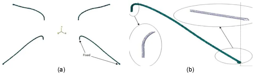
3.2. Wire Model and Boundary Conditions in ABAQUS
Commercial FEM based software; ABAQUS was used in this study to calculate the wire deformation. The structures of the wires were imported from GAMBIT in ACIS (.sat) format. The dimension of the wire is built according to Sen et al. [19] model. The wire bond span has a length, L = 20 mm and height of wire, H = 3.5 mm. The ball bond boundary conditions of wire were set as fixed in ABAQUS and shown in Figure 3(a). The wire bond in this validation is divided into 10,191 tetrahedral elements which have been shown in Figure 3(b).
(a) (b)
The shape of the wire as also classified as typical Q-auto loop wire bond [3]. The wire mechanical properties are as follows: elastic modulus, E=50 GPa [26], density, ρ=1800 kg/m3, Poisson’s ratio, ν= 0.42 and reference temperature, T=175°C.
3.3. Code Coupling with MpCCI
MpCCI nowadays is the most widely used software for the coupling of several codes. The MpCCI works quite well for a fixed pair of codes [27]. MpCCI is a software library, which enables the exchange of data defined on meshes of two or more simulation codes in the coupling region. Since the meshes need not match point by point, MpCCI performs an interpolation and, in case of parallel codes, keeps track of the distribution of the domains onto different processes [15]. In this way, the intricate details of the data exchange are hidden behind the concise interface of MpCCI. The design of MpCCI was driven by the demand for creating a general library for coupling of any simulation code to another [16]. The basic concepts of MpCCI are [28]: loose coupling between codes, minimal source code changes, minimal knowledge of the other codes, support for sequential, distributed, parallel execution, and portability.
The MpCCI library provides neighborhood search and various types of interpolation [17]. All kinds of coupling areas such as lines, surfaces, and volumes are supported.For the communication between the involved codes, message passing interface (MPI) is used [18]. For parallel simulation codes MpCCI guarantees the separation of the internal and external code communication. MpCCI offers easy to use concepts for implementation of different coupling algorithms. Additionally, MpCCI provides useful control facilities like convergence checks, debugging, and monitor facilities.
At the interface between fluid and structure have some mapping of data between two, in general non-matching grid. In the MpCCI concept, this mapping is done directly from one solver to the other with the help of either given library routines. This implies that each solver has to know the grid of the other solver and, thus, inhibits the exchange of one solver without changing the code of the other one.
Running a co-simulation with MpCCI require the process given in [29]. There are four steps of the complete co-simulation. The first, preparation of model files, the second, the definition of the coupling process, the third, running the co-simulation and the fourth, post processing. The each domain modeled separately and created for each simulation code. The models contain a definition of the coupling region. Simulation codes, corresponding model file and the coupled region, quantities and a coupling algorithm must be selected. This step is completely supported by the MpCCI GUI. After starting the MpCCI server, both coupled codes are started. Each code computes its part of the problem while MpCCI controls the quantity exchange. After the co-simulation, the results can be analyzed with the post-processing tools of each simulation code, with the FLUENT and ABAQUS visualizer.
For the fluid structure coupling an implicit portioned approach is employed. After the initializations the flow field is determined in the actual flow geometry. From this, the friction and pressure forces on the interacting walls are computed, which are passed to the structural solver as boundary conditions. The structural solver computes the deformations, with which then the fluid mesh is modified, before the flow solver is started again.
4. Result and Discussion
(a) (b)
(c) (d) Figure 5. Comparison of melt front profiles for all type inlets
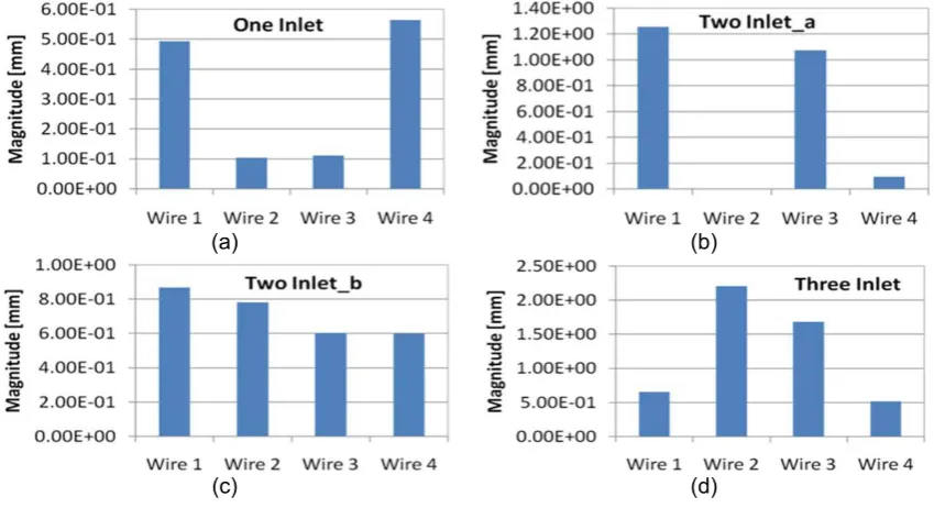
The magnitude of wire sweep is presented in Figure 6. From the simulation results, it was found that the increased number of inlet gates raised the wire sweep during the encapsulation process. The simulation results revealed the wire located perpendicular to the flow direction has the higher deflection. This is because the wire experienced higher drag force when fluid-structure interaction occurs. Besides, the location of the inlet gate also affects the wire sweep behavior. Figure 6(a) and (b) illustrates two inlet gates at different positions.
(a) (b)
(c) (d)
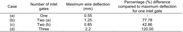
All wires were deformed when the two inlet gates located opposite to each other. Table 2 summarizes the percentage difference of maximum wire deflection compared to one inlet gate (case a) encapsulation process. From the analysis, the increase in inlet gate has raised the maximum wire deflection around 43 to 120%. From the simulation results, more inlet gates yielded shorter filling time, but caused higher wire deformation. In the manufacturing aspect, shorter filling time may minimize the production cost, but with higher wire deflection may yield the higher product rejection rate. Therefore, to control the filling time without sacrifice the reliability of the IC package, the design of IC package is significant to minimize the wire sweep during the encapsulation process.
Table 2. Percentage difference (%) of maximum wire deflection
Case Number of inlet
In the present finite volume method (FVM) simulation, the fluid flow is validated with experimental result of the previous work [18], which investigated the flow behavior and the epoxy resin used is D.E.R.331 (Dow Chemical). The wire deformation is validated with analytical methods, based on eq. (14), which proposed, by Kung et al. [5]. The equation of displacement indicated that displacement is contributed by the bending moment-induced and the torsion or twisting moment- induced.The mold temperature was heated to 175oC and the package inlet velocity was 0.6 m/s.
Figure 7 shows the comparison of the simulation results and experimental of plastic ball grid array (PBGA) encapsulation process from 39.9% to 97.4% EMC volume. The simulation results show the wire profile that presented in line contour, however EMC is presented in total volume filled profile in different filling time. From the observation of both simulation and experimental results, it was found the EMC shows the similar profile with the experimental results. The wire displacement phenomenon is observed when the EMC flows around the wire region.
The experiment result and predicted flow front profiles show a good agreement at all filling times. The EMC volume versus filling time for the simulation and the experiment of encapsulation process is plotted in Figure 8(a). The maximum deviation of the result is about 6.7 %. This demonstrated that the capability of the FLUENT software in solving the encapsulation process that involves polymer rheology.
Moreover, the comparison simulation and analytical results of wire deformation for wire 4 of x-direction is shown in Figure 8(b). The analytical calculation refers to Equation (14), fB is selected 0.165 and fT is selected 0.00165 [4] for H/L = 0.175. The average deviation at maximum displacement (after 9 s) was only 6.5 %. The results demonstrate good quantitative agreement. This indicated that the prediction of the wire deformation using the ABAQUS software is reliable and realistic.
Figure 7. Comparison of EMC profile for experiment [21] and simulation and wire deformation profile
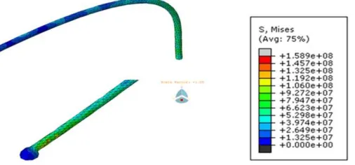
(a) (b)
Figure 9. Detailed view of Von-Mises stress distribution for wire 1
6. Conclusion
Visualization of wire sweep during PBGA package encapsulation process was presented, and a new three-dimensional (3D) computational technique for fluid structure interaction (FSI) in the process by using Mesh based Parallel Code Coupling Interface (MpCCI) has been investigated. The computational techniques used for two ways couple’s computing between the fluid and the structural dynamics stresses and deformation of wires were described. Wire sweep profiles were validated by analytical results with 6.5% of maximum deviation.The numerical results of melt front patterns and filled volume were compared with the previous experimental results and found in good agreement. The proposed technique of MpCCI Code Coupling in handling FSI on wire sweep during the encapsulation process was proved to be excellent. This present work is expected to be a reference and guideline for improvement and design consideration in the microelectronics industry.Future work will focus on evaluating the impact of various parameters ultimately inputting these correlations into an analytical numerical model for predicting maximum wire displacement.
Acknowledgements
The authors gratefully acknowledge the Intel Corporation Malaysia for supplying MpCCI Software for supporting this research work. The author would also like to thank Menristek Dikti for the Competitive Research Grant Skim Program FY 2014/2015.
References
[1] Ardebiri H, Pecht M. Encapsulation Technologies for Electronic Applications. USA: Elsevier Inc. 2009: 1-46.
[2] Ramdan D, Khor CY, Abdullah MZ. Plastic Ball Grid Array Encapsulation Process Simulation on Rheology Effect, Telecommunication Computing Electronics and Control. TELKOMNIKA. 2011; 9(1): 29-38.
[3] Brand JM, Ruggero SA, Shah AJ. Wiresweep reduction via direct cavity injection during encapsulation of stacked chip-scale packages. Journal of Electronics Packaging. 2008; 130: 1-6. [4] Kung HK, Sun YP, Lee JN, Chen HS. A Method to determine the sweep resistance of wire bonds for
microelectronic packaging. Microelectronic Engineering. 2008; 85: 1902-1909.
[5] Kung HK, Lee JN, Wang CY. The wire sweep analysis based on the evaluation of the bending and twisting moments for semiconductor Packaging. Microelectronic Engineering. 2006; 83: 1931-1939. [6] Su J, Hwang SJ, Su F, Chen SK. An Efficient Solution for Wire Sweep Analysis in IC Packaging.
Journal of Electronic Packaging, ASME. 2003; 125: 139-143.
[7] Yao YF, Njoman B, Chua KH, Lin TY. New Encapsulation development for fine pitch IC devices,
Microelectronics Reliability. 2005; 45: 1222-1229.
[8] Pei CC, Hwang SJ. Prediction of Wire Sweep During the Encapsulation of IC Packaging with Wire Density Effect. Journal of Electronic Packaging, ASME. 2005; 127: 335-339.
[9] Yao YF, Lin TY, Chua KH. Improving the deflection of wire bonds in stacked chip scale package (CSP). Microelectronics Reliability. 2003; 4: 2039-2045.
[10] Liu DS, Chao YC, Wang CH. Study of wire bonding looping formation in the electronic packaging process using the tree-dimensional finite element method. Finite Elements in Analysis and Desig.
[11] Jong WR, Chen YR, Kuo TH. Wire density in CAE analysis of high pin count IC packages: Simulation and verification. International Communications in Heat and Mass Transfer. 2005; 32: 1350-1359.
[12] Yang H. A Pedagogical Approach for Modeling and Simulation of Switching Mode DCDC Converters for Power Electronics Course. TELKOMNIKA Indonesian Journal of Electrical Engineering. 2012; 10(6): 1319-1326.
[13] Yang HQ, Mazumder S, Lowry S, Krishnan A, Przekwas A, Nguyen L. Time-accurate, 3-D computation of wire sweep during plastic encapsulation of electronic components. Journal of Pressure Vessel Technolog. 2001; 123: 501-509.
[14] Yigit S, Schafer M, Heck M. Grid movement techniques and their influence on laminar fluid-structure interaction computations. Journal of Fluids and structures. 2008; 24: 819-82.
[15] Thirifay F, Geuzaine P. Numerical simulations of fluid-structure interaction problem using MpCCI. 2008.
[16] Gatzhammer B, Mehl M, Neckel T. A coupling environment for portioned multiphysics simulations applied to fluid-structure interaction scenarios. Procedia Compuer Science I. 2010: 681-689.
[17] Joppich W, Kurschner M. MpCCI a tool for the simulation of coupled applications. Concurrency and Computation: Practice and Experience. 2006; 18: 183-192.
[18] Schreiber A, Metsch T, Kersken HP. A problem solving environment for multidisciplinary couple simulations in computational grids. Future Generation Computer System. 2005; 21: 942-952.
[19] Han S, Costa F. Wire sweep analysis in transfer molding and compression molding process for semiconductor chip encapsulation. 72nd Annual Technical Conference of the Society of Plastics Engineers: The Plastics Conference, ANTEC 2014. Las Vegas, United States. 2014; 113016: 795-800.
[20] Ali SSS, Hian STS, Ang BC. The effects of wire geometry and wire layout on wire sweep performance using LQFP packages in transfer mold. International Journal of Precision Engineering and Manufacturing. 2014; 15(9): 1793-1799.
[21] Yang SY, Jiang SC, Lu WS. Ribbed package geometry for reducing thermal warpage and wire sweep during PBGA encapsulation. IEEE Transactions on Components and Packaging Technologies. 2000; 23(4): 700-706.
[22] Khor CY, Abdullah MZ, Ariff ZM, Leong WC. Effect of stacking chips and inlet positions on void formation in the encapsulation of 3D stacked flip-chip package. International Communications in Heat and Mass Transfer. 2012; 39(5): 670-680.
[23] Khor CY, Abdullah MZ. Optimization of IC encapsulation considering fluid/structure interaction using response surface methodology. Simulation Modelling Practice and Theory. 2012; 29: 109-122. [24] Han SJ, Huh YJ. A study of wire sweep during encapsulation of semiconductor chips. Journal of the
Microelectronics and Packaging Society. 2000; 7(4): 17-22.
[25] Nguyen L, Quentin C, Lee W, Bayyuk S, Bidstrup-Allen SA, Wang ST. Computational Modeling and Validation of the Encapsulation of Plastic Packages by Transfer Molding. Transaction of the ASME. 2000; 122: 138-146.
[26] Yang WH, Hsu DC, Yang V, Chang RY, Su F, Huang SJ. Thee dimensional CAE of wire-sweep in microchip encapsulation. Technical Conference-ANTEC, Conference Proceeding. 2004; 2: 1769-1683.
[27] K Wolf. MpCCI the general code coupling interface. Dynamore GmbH, LS-Dyna Anwender Forum. 2007: 1-8.
[28] Hackenberg MG, Post P, Redler R, Steckel B. MpCCI, multidisciplinary application and multigrid, European Congress on Computational Methods in Applied Sciences and Engineering. Barcelona. 2000.
[29] MpCCI 3.1.0-1 Documentation part I overview. Fraunhofer Institute for Algorithms and Scientific Computing SCIA. Germany.
![Table 1. Material properties of EMC used in the mold filling analysis [24]](https://thumb-ap.123doks.com/thumbv2/123dok/244792.503420/3.595.118.479.352.534/table-material-properties-emc-used-mold-filling-analysis.webp)
![Figure 8. (a) Comparison of EMC filled volume for experiment [21] and simulation, (b) Comparison simulation and analytical results of wire deformation for wire 4 of x-Direction](https://thumb-ap.123doks.com/thumbv2/123dok/244792.503420/9.595.139.451.84.461/comparison-experiment-simulation-comparison-simulation-analytical-deformation-direction.webp)