DOI: 10.12928/TELKOMNIKA.v14i1.2755 440
Model Predictive Optimization Control Strategy for
Three-level AFE Converter
Xiaoyan Shi*, Longji Zhu, Shuijuan Yu
Department of automation, Collgege of Electrical and Information Engineering, Anhui University of Science and Technology, Huainan 232001, Anhui, China
*Corresponding author, e-mail: shixiaoyan1980@163.com
Abstract
In view of the fact of traditional MPC prediction for three-level AFE converter with numerous switching vectors, time-cost computation and complex control, a simplified model predictive control algorithm is proposed in this paper. The multiple current prediction is transformed into a single virtual reference voltage vector prediction according to the inverse procedure of the model current prediction, and vector distribution method is adopted which can screens out the optimal vector. In the process of rolling optimization, multi-objective control is carried out by adding neutral point potential balance and reducing switching losses and other constraints to the cost function. Also the control delay of the algorithm is compensated. Finally, simulation experiments of three-level AFE converter under steady-state and dynamic conditions are provided. The results have verified correctness and practicability of the strategy.
Keywords: Three-level AFE converter, Model predictive control, Virtual reference voltage, Vector sector
Copyright © 2016 Universitas Ahmad Dahlan. All rights reserved.
1. Introduction
With the advantages of low voltage harmonic, high power factor and bidirectional energy flow, multi-level active front end (AFE) converter has been widely used in active power filter, reactive power compensation, and new energy grid generation and so on [1]. The control targets of the multi-level converter are not only to adjust the current of the AC side rapidly, suppress the harmonics, and adjust power factor, but also the problems of neutral point potential fluctuation and power device loss should be considered. For above purposes, domestic and foreign scholars have conducted in-depth research on its control strategy, which mainly include voltage oriented control (VOC) and direct power control (DPC) [2]. However, due to the time-variability and nonlinearity, it is difficult to achieve the best control effect. In recent years, with the rapid development of digital processors, some complex and new control strategies, such as adaptive control, sliding mode control, fuzzy control, predictive control etc, are well implemented [7, 8].
To simplify the prediction process and reduce the computation time,the paper discusses the voltage prediction control model of the neutral point clamped (NPC) AFE converter based on FCS-MPC. First, according to the inverse procedure of the model current prediction the single virtual reference voltage vector is obtained. Then the cost function of the output voltage is expressed by the equivalent transformation and some constraint conditions are introduced to the cost function to realize multi-object control. Finally, the optimal switching state is determined and taken as the output of the controller. For the control delay of algorithm, the compensation scheme is also presented. In order to verify the correctness and feasibility of the algorithm, the three-level AFE converter simulation experimental platform is built based on Matlab/simulink. The results indicate that the proposed strategy has a good static and dynamic performance.
2. Traditional Current Model Predictive Control of Three-level AFE Converter
For improving the voltage level, reducing the volume of the whole system effectively, suppressing the harmonic pollution, the NPC multi-level AFE converter can meet the development requirements of smart grid in the future. The traditional model predictive control strategy used discrete mathematics model to calculate current predictive value under the different states of the switch and make the switch condition selected through cost function when the current predictive value and the command current value is closest [10, 11]. Therefore, a key part of the model predictive control strategy is to establish discrete mathematics model of the system and evaluate the switch state control behavior by the cost function.
2.1. Mathematics Model of Three-level AFE Converter
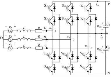
The NPC three-level AFE converter topology structure is shown in Figure 1.
Figure 1. The three-level AFE converter circuit topology
, ,
a b c
e e e are power grid voltage, i i ia, ,b c are AC side current, idcis DC side current; L and R are AC side inductance and equivalent resistance; C C1, 2 are the two capacitor capacitance value corresponding to the DC side. Assuming symmetry of the three-phase AC voltage and ignoring the asymmetry of the grid side resistance and the filter inductance, the mathematical model of three-level AFE converter in the coordinate can be described as following:
,
, , ,
di
L e u Ri
dt
(1)
, , ( 1) , ( )
According to (1), (2), the discrete prediction model of the converter is obtained.
, ( 1) [ , ( ) , ( )] (1 ) , ( )
simultaneously conducting, Sa 1, a point to o point level is
2
DC side. Therefore, the three-level AFE converter AC side has 33 27 kinds of voltage state combination. The AC side voltage vector u u, can be get from the DC bus voltage of the
three-level AFE converter and the switching state S S Sa, b, c.
2.2. Determination of Cost Function
Current model predictive control strategy by using the finiteness of power device on-off state and according to the discrete mathematical model of the controlled object predict the future value of the input current in different switching states. However, in order to ensure good control performance and enhance the reliability of the whole system, the fluctuation of neutral point potential is a problem that can not be ignored.For three-level AFE converter system, based on the prediction of the future state of the 27 switch one by one,the optimal switching state is determined by using the cost function to achieve current tracking and maintain the balance of neutral point potential. Considering the existence of midpoint potential fluctuating problem of three-level topology, the predicted value Udc(k1) of the neutral point potential
deviation at (k1)T is expressed as following:
Nowadays the AFE converters control systems are generally based on the technique of PWM modulation. Shorten the period of the modulation algorithm would increase the output voltage of the fundamental wave content and reduce the harmonic distortion of the AC side current. However, the periodic modulation of the relationship means to increase the switching frequency of power devices, which will directly affect the efficiency and temperature of converter. Therefore, that is needed to weigh main control objectives and switching frequency. So the cost function determination contains multiple factors.
2 *
1 , ( 1) , ( 1) 2 dc( 1) 3 s( 1)
J i k i k U k f k (6)
Given current value * , ( 1)
i k can be obtained by two order trend extrapolation.
* * * *
, ( 1) 3 , ( ) 3 , ( 1) , ( 2)
( 1)
s
f k is the average number of circuit switches at the (k1)T . The switching loss is relevant to switching voltage and current. It is not a simple linear relationship with switching frequency. In general, the average switching frequency is smaller, lower switching losses, so algorithm selection average switching frequency is used as one of the optimization index.
, , voltage and average switching frequency weights. By weighting coefficients to adjust the value of the function can flexibly and conveniently optimize the overall performance of the AFE converter, which it is very difficult for the conventional control methods to do this.
3. Three-level AFE Converter Voltage Predictive Control
Model predictive control algorithm loops once in each control cycle. The running time of the algorithm should be short enough to obtain a higher sampling frequency, so the complexity of the algorithm needs to be reduced. In order to select the optimal switching state from the 27 switching states and make the current value of the future i , (k1) as close as possible to the
current reference value * , ( )
i k , a simplified predictive control algorithm is proposed by inverse
thinking. According to the mathematical model of the AFE converter, assumpting the existence of voltage vector *
, ( )
u k is called 'virtual reference voltage vector'. For the FCS-MPC algorithm,
only outputing a voltage vector each control period, the nearest voltage vector to * , ( )
u k is
optimal voltage vector uOPT. The final cost function J is selected as following:
2 *
1 , ( 1) , ( 1) 2 dc( 1) 3 s( 1)
J u k u k U k f k (10)
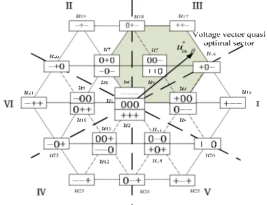
In the presented algorithm, the 26 times current prediction process is simplified as a single virtual reference voltage vector prediction, then the calculation is greatly reduced. Based on the FCS-MPC single prediction method, using the vector distribution method can determine the optimal switching state. The space voltage vectors of all the switching states of the three-level AFE converter are shown in Figure 2. The three-phase bridge arm switch state '1', '0' and '-1' respectively are expressed by the symbol '+', '0', '-'. The three level space vectors are divided into 6 large sectors, which the switch state of each vector is adjacent.
For example, when * , ( )
u k in the third sector III, compared to other voltage vectors,
0, ,1 2, 5, 6, 16, 17, 18
u u u u u u u u are more close to *
, ( )
u k , then the current constraints are relatively
*
u,
Figure 2. Voltage vectors distribution
Table 1. Selection of candidate vectors for each sector
Sector Ι
Sampling and getting the kth times
,
∗ , , , ,
Predicting
,
∗ ,
according expression (7) and (9)
Judging sector and getting S(N)
Predicting i
, k ,∆
according expression (7) and (9)
i=N?
Predicting i, k ,∆
according expression (7) and (9)
Searching the discrete voltage vector near uOPT. can determine the final MPC system
optimal switching state. The flow chart of FCS-MPC algorithm is shown in Figure 3.
i
is defined as the loop variable, JOP is the value of the optimal cost function. S i(OP)is output optimal switching signal. The algorithm is put in the timing interrupt routines. When the timer interrupt is triggered, the switching signals for the first cycle begin to affect the actual hardware circuit, and voltage and current sampling start up.Before the rolling optimization the optimal voltage vector uOPT. of the system is obtained by the Equation (9). The determined discrete voltage vector is put in S N[ ]. N is the number of FCS-MPC rolling optimization. Taking into account voltage space vector distribution characteristics of the three-level topology, the value of N can be 4, 5, and 7. Then rolling optimization only needs to be carried out 7 times, which greatly enhance the system online searching efficiency.
4. Control Delay and Compensation Scheme
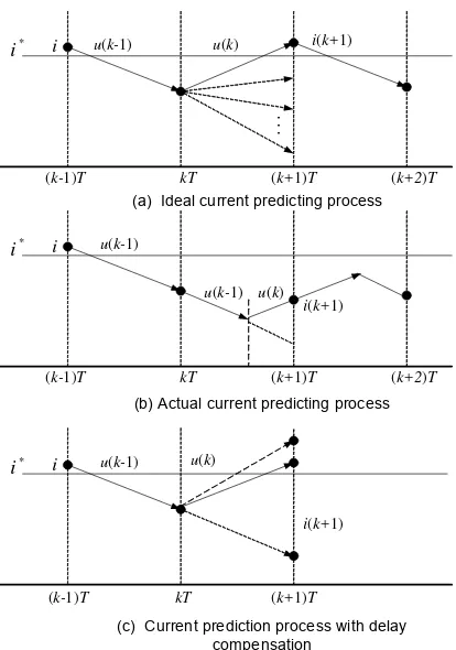
Ideally, AD sampling, algorithm calculation, control signal action of MPC control system should be completed at the same time. But actual digital processing system has consumed certain program execution time, so the control signal is bound to delay a period of time after output. In the design process of the AFE converter controller, control delay effect is an issue that should not be ignored.
* i
(k-1)T kT (k+1)T (k+2)T
u(k-1)
...
i
* i
(k-1)T kT (k+1)T (k+2)T
u(k-1) i
u(k) i(k+1)
u(k-1) u(k)
i(k+1) (a) Ideal current predicting process
(b) Actual current predicting process
*
i i u(k-1) u(k)
i(k+1)
(k-1)T kT (k+1)T
(c) Current prediction process with delay compensation
Figure 4. Current prediction process
, ,
The treatment of neutral point potential is consistent with the grid side current. According to the Equation (7) the midpoint potential udc(k2)T is obtained.
The optimal switching state of the rolling optimization moment is determined by the state of the (k2)T, and is kept to the(k1)T. In essence the delay compensation belongs to multi-step prediction. Based on discrete predict model of system in a sampling period Ts, multi-step prediction are carried out to compensate and correct the influence of the control delay caused by the optimal switching state.
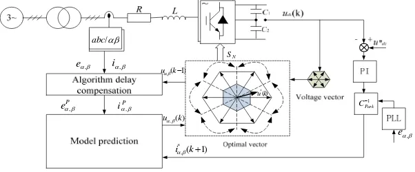
To sum up, the structure of the control system based on FCS-MPC algorithm is shown in Figure 5. The DC bus voltage is adjusted by the PI controller, and the current reference value is generated. According to the model predictive control theory, the voltage u , ( )k is predicted which is needed to track the reference current in the coordinate. Then optimal voltage vector is taken as the output of the controller determined by the sector of the voltage u , ( )k
location.
Figure 5. The structure of the control system based on FCS-MPC
5. Simulation and Analysis
In order to verify the correctness of the proposed FCS-MPC control algorithm, Simulation study of control system in Figure 5 is presented based on Matlab/Simulink. System simulation parameters are listed in Table 2.
Table 2. System simulation parameters
List Parameters Value
1 Grid sidevoltagefrequency f/Hz 50Hz
2 Electricity grid line voltage eab/V 90V
3 DC side capacitor C/μF 2500μF
4 Line inductance L/mH 1.5mH
5 Load resistance R/Ω 8Ω
6 Sampling frequency /kHz 10kHz
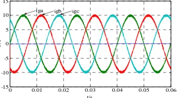
Figure 6. Steady state current waveform Figure 7. A phase current spectrum analysis
The result in Figure 6 indicates input current of the system is stable. Waveform is almost sinusoidal and the unit power factor can be realized. The current spectrum analysis shows that the total harmonic content of A phase current is 2.96% in Figure 7. The current harmonic content is lower, and the control effect is good.
To further analysis the validity of the FCS-MPC proposed in this paper, dynamic current changed process is conducted. When reference current value is rised from 10 A to 12A at 0.03s, the output current are demonstrated in Figure 8(a). Reference current value is decreased from 10 A to 8A in Figure 8(b). The current step time is about 0.2ms. Then it can be found that the response speed is relatively fast.
(a) Reference current step rise (b) Reference current step fall
Figure 8. Dynamic simulation results with reference current changed
The sampling periodTs is 100s, AD sampling time of digital processing system is about 5s, predictive control rolling optimization time is about 40s, the total control delay is about td 45s. Considering the large proportion of td in sampling period Ts, the delay compensation strategy is needed to overcome the problem that the AD sampling point is not matched with the switching state action time. In Figure 9 the steady-state waveform with and without control delay compensation are illustrated. As finding in the figure, the output current ripple is smaller with time delay compensation of MPC system under the same sampling frequency and given current situation, whch has more excellent current tracking accuracy.
(a) Simulation results without delay compensation
(b) Simulation results with delay compensation
6. Conclusion
As an advanced converter control technology, FCS-MPC control strategy is applied to the control of three-level AFE converter in this paper. For the problems existing in the traditional model current prediction, a simplified model voltage prediction control algorithm is proposed. The virtual voltage prediction and voltage vector division method is introduced to select the optimal voltage vector. It has overcomed effectively the defects of low efficiency of traditional MPC algorithm. Finally, the simulation results show that the proposed strategy have a good static and dynamic performance, which has provided a simplified method for the design of multi-level converter MPC system.
References
[1] Zaragoza J Pou J, Ceballos S, et al. A comprehensive study of a hybrid modulation technique for the neutral-point-clamped converter. IEEE Transactions on Industrial Electronics. 2009; 56(2): 294-304. [2] Kadri R, Gaubert J P, Champenois G. An improved maximum power point tracking for photovoltaic
grid-connected inverter based on voltage-oriented control. IEEE Transactions on Industrial Electronics. 2011; 58(1): 66-75.
[3] Lee JH. Model predictive control review of the three decades of development. International Journal of Control, Automation and Systems. 2011; 9(3): 415-424.
[4] Atif Iqbal, Shaikh Moinoddine, Khaliqur Rahman. Finite State Model Predictive Current and Common Mode Voltage Control for a Sevenphase VSI. International Journal of Power Electronics and Drive Systems. 2015; 6(3): 459-476.
[5] Gu Xin, Zhang Ce, Geng Qiang, Shi Tingna. Simplified model current predictive control of three-level rectifier. Advanced Technology of Electrical Engineering and Energy. 2014; 33(2): 12-17.
[6] M Elsisi, MAS Aboelela, M Soliman, W Mansour. Model Predictive Control of Two-Area Load Frequency Control Based Imperialist Competitive Algorithm. TELKOMNIKA Indonesian Journal of Electrical Engineering. 2015; 16(1): 75-82.
[7] Cao Xiaodong, Tan Guojun, Wang Conggang. Model predictive virtual voltage vector control for three-phase PWM rectifiers. Proceedings of the CSEE. 2014; 33(18): 2926-2935.
[8] Vargas R, Cortes P, Ammann U, et al. Predictive control of a three-phase neutral-point-clamped inverter. IEEE Transactions on Industrial Electronics. 2007; 54(5): 2697-2705.
[9] Liu Pu, Wang Yue, Cong Wulong, et al. Researches on optimized model predictive control for modular multi-level converters. Proceedings of the CSEE. 2014; 34(36): 6380-6388.
[10] Wang Yinsong, Wang Shuyuan. Multi-step Predictive control for output current of three-phase grid-connected inverters. Smart Grid. 2015; 3(3): 223-228.
[11] Vazquez S, Leon JI, Franquelo LG, et al. Model predictive control with constant switching frequency using a discrete space vector modulation with virtual state vectors. IEEE International Conference on Industrial Technology. 2009: 1-6.
[12] Malinowski M, Kazmierkowski MP. A comparative study of control techniques for PWM rectifiers in ac adjustable speed drives. IEEE Transactions on Power Electronics. 2003; 18(6): 1390-1396.