ii
SUPERVISOR DECLERATION
“I hereby declare that I have read this thesis and in my opinion this thesis is sufficient in terms of scope and quality for the award of the degree of Bachelor of Mechanical
Engineering (structure and Material with Honors)”
Signature: ………..
Supervisor: ………..
iii
DECLARATION
“I hereby declare that the work in this thesis sufficient in terms of scope and quality for the award of the degree of Bachelor of Mechanical Engineering (Structure and
Material with Honors)”
Signature: ………..
Name: ………..
iv
v
ACKNOWLEDGEMENTS
I would like to express my gratitude to my supervisor, Professor Madya Ahmad Rivai for his indispensable guidance and advice that he afforded me throughout the duration of this report. I am very much appreciating the time he has taken out of his schedule to offer helpful advice. Without his provision of supports, it would have been impossible to have this thesis completed.
I like to take this chance to thanks to Encik Ahmad Fitri Faizee from KKTM and all of the UTeM technician who give me full cooperation and help me to complete all the task. Not forgot to all my friend who give me moral support.
Finally, I would like to recognize the significant contribution of my family throughout the duration of mu undergraduate degree. I genuinely appreciate their continual support especially my parent, Mohamad Rus Yusuf and Hayati Jaafar. With their support, I have made this far.
vi
ABSTRACT
vii
ABSTRAK
viii
TABLE OF CONTENTS
CHAPTER TOPIC PAGE
DECLARATION iii
ACKNOWLEDGEMENTS v
ABSTRACT vi
ABSTRAK vii
LIST OF FIGURE xi
LIST OF TABLE xiii
LIST OF ABBREVIATION xvi
LIST OF APPENDIX xvii
CHAPTER 1 INTRODUCTION 1
1.1 Background 1
1.2 Problem Statement 3
1.3 Objective 4
1.4 Scope 4
CHAPTER 2 LITERATURE REVIEW 5
2.0 Material Composite 5
ix
CHAPTER TOPIC PAGE
2.0.1.1 Dry Carbon 7
2.1.1 Thermoset resin 8
2.1.1.1 Epoxy 9
2.2 Product Development or Processing Method 10
2.2.1 Compression Molding 10
2.2.2 Filament Winding 11
2.3.3 Hand Lay-up 12
2.3.4 Prepreg Molding 13
2.2.5 Pultrusion 15
2.2.6 Resin Transfer Molding 16
2.3.6.1 The Mold 17
2.3.6.2 The Reinforcement 18
2.3.6.3 The Pump 18
2.3.6.4 The Resin 19
2.3 Specimen Testing 19
2.3.1 Tensile Test 19
2.3.2 Instron Machine 20
2.3.3 Stress Strain Relationship 21
2.3.4 Tensile Strength 23
2.3.5 Young’s Modulus 23
x
CHAPTER TOPIC PAGE
CHAPTER 3 METHODOLOGY 25
3.1 Work Flow Chart 25
3.2 Mold 26
3.3.1 Procedure 27
3.3 Resin Transfer Molding (RTM) 28
3.3.1 Major application 28
3.3.2 Basic raw material 29
3.3.3 Tooling 29
3.3.4 Making of the part 31
3.3.5 Methods of applying heat and pressure 32
3.3.6 Procedure of RTM 33
3.4 Tensile Test 33
3.4.1 specimen 34
3.4.2 Procedure 34
CHAPTER 4 DATA AND RESULT 36
4.0 Composite Fabrication BY Using Resin Transfer Molding 36 4.1 Tensile Test Result For Specimen Fabricated By Using
Resin Transfer Molding 37
CHAPTER 5 ANALYSIS AND DISCUSSION 41
xi
CHAPTER TOPIC PAGE
5.2 Fracture Behavior of Tested Materials 45
CHAPTER 6 CONCLUSION AND RECOMMENDATION 47
6.1 Conclusion 47
6.2Recommendation 47
REFERENCES 49
xii
LIST Of FIGURE
NO TITLE PAGE
FIGURE 2.1 Dry Carbo 8
FIGURE 2.2 Compression Molding Schematic Diagram 11
FUGURE 2.3 Filament Winding Molding schematic diagram 19
FIGURE 2.4 Hand Lay Up schematic diagram 13
FIGURE 2.5 Prepreg Schematic diagram 14
FIGURE 2.6 Pultrusion Schematic diagram 16
FIGURE 2.7 Resin Transfer Molding schematic diagram 17
FIGURE 2.8 Diagram of specimen 20
FIGURE 2.9 Schematic of Instron Machine 21
FIGURE 2.10 The relationship between stress strain 22
FIGURE 3.1 Schematic of RTM process 31
FIGURE 3.2 Instron Universal Testing Machine 34
FIGURE 4.1 Specimen of Dry Carbon composite 36
xiii
FIGURE 5.6 Specimen Fracture for two ply of Dry Carbon 46
LIST OF CHART
NO TITLE PAGE
CHART 1. Flow Chart of Work 24
xiv
LIST OF TABLE AND GRAPH
NO TITLE PAGE TABLE 4.1 Result of Tensile Test for one ply of Dry Carbon 39 TABLE 4.2 Result of Tensile Test for two ply of Dry Carbon 39
TABLE 4.3 Properties of Dry Carbon Composite 40
TABLE 5.2 Strength percentages different between RTM and Hand Lay Up method 43
xv
LIST OF ABBREVIATION
UTeM University Teknikal Malaysia Melaka RP Rapid Prototyping
UV Ultra Violet C Carbon Dioxide
DGEBA Dglycidyl Ether of Bisphenol SMC Sheet Molding Compound RTM Resin Transfer Molding cP Coefficient of Pressure CAD Computer Aided Design STL Stereo Lithography
SRIM Stopping and Range of ions in Matter MIN Minutes
1
CHAPTER 1
INTRODUCTION
1.1 BACKGROUND
One of advance technology in aerospace technology is a spoiler technology. Spoilers are hinged, rectangular plate, like structures installed flush along the top of an aircraft wings. Just forward of the flaps. When the pilot activates the spoiler, the plate pivot up on their center hinge fitting into the airstream. The airflow over the wing is disturbed and lift is decreased. Maximum deployment of the spoiler would be about 50° from the flush position. The spoiler is a multifunctional flight control surface with three main functions, in-flight air braking for speed reduction. In-flight roll control for augment ailerons in turning, and air-braking on the ground during lift dumping. The latter dispels the remaining lift as an aircraft touches down on a runway. This increases the efficiency of the wheel brakes by applying the full weight of the aircraft on the wheels.
2
composites; so is concrete: both were known to the Romans. And almost all materials which must bear load-wood, bone, muscle-are composites.
The composites industries, however is much more recent. It has grown rapidly in the past 60 years with the development of fiber composites starting with glass-fiber reinforced polymers (GFRP) and Kevlar-fiber reinforced polymers (KFRP). Their use in boats, and their increasing replacement of metals in aircraft and ground transport system, is a revolution in material usage which is still accelerating.
Plywood is a lamellar composite, giving a material with uniform properties in the plane of the sheet (unlike the wood from which it is made). Sheet of GFRP or CFRP are laminated together, for the same reason. And sandwich panels-composites made of stiff skins with a low-density core-achieve special properties by combining, in a sheet, the best features of two very different components.
Cheapest of all are the particulate composites. Aggregate plus cement gives concrete, and the composites are cheaper than the cement itself. Polymers can be filled with sand, silica flour, or glass particles, increasing the stiffness and wear resistance, and often reducing the price. And one particulate composite, tungsten carbide particles in cobalt, is the basis of the cutting tool industry.
But high stiffness is not always what you want. Cushions, packaging, and crash padding require materials with moduli that are lower than those of any solid. This can be done with foams-composites of a solid and a gas which have properties that can be tailored, with great precision, to match the engineering need.
3
community and had to be redeveloped 25 years after the last patent was applied for The RTM are based on liquid injection method. The composite resin will injected to the closed mold of hinge using RTM machine. RTM is not a new process. It has been used in one form or another since the early 1940’s. However, its use was limited until the 1970’s because of the lack of suitable resins and equipment. In the 1980’s fiber preforms and low viscosity resins were developed that allowed the production of more complex geometries and parts for more diverse applications. This, combined with low capital investment and release of volatiles, has dramatically improved the popularity of RTM.
1.2 PROBLEM STATEMENT
Nowadays the properties and the behavior of the material is the crucial aspect need to be considered in developing the fabrication process. The metal material has lots of weakness such as it doesn't resist to corrosion and has higher weight. To improve the design in term of weight of material, resistance to corrosion and cost saving, the new design will be developed by using composite material. The fabrication cost of the conventional composite using autoclave is quite high. For that reason the cheaper method was chosen. After doing some research, resin transfer molding (RTM) method is founded as the cheaper method for fabrication compared to autoclave method.
1.3 OBJECTIVE
Fabricate composite specimen by using Resin Transfer Molding at Kolej Kemahiran Tinggi Mara Masjid Tanah Melaka.
Investigate mechanical properties of material composite made with epoxy as reinforcements and dry carbon as matrix through Tensile Test.
4
1.4 SCOPE
5
CHAPTER 2
LITERATURE REVIEW
2.0 MATERIAL COMPOSITE
The advanced material was developed rapidly to improve the performance of the part. The scientist and industries do some research about the material to produce material or product that is lighter, stronger and more efficient. This proved by automotive and aerospace industries, with increase of the fuel cost will influence the operation cost of the vehicle. For that reason the manufacturer makes an effort to increase fuel efficiency without increasing product cost, by increasing the product performance and achieving low cost target.
6
are stronger than synthetic fibers. In India, Greece, and other countries, husks or straws mixed with clay have been used to build houses for several hundred years. Mixing husk or sawdust in a clay is an example of a short-fiber composite. This reinforcement is done to improve performance.[10]
Typically, composite material is formed by reinforcing fibers in matrix resin. The reinforcements can be made from polymers, ceramics, and metals. The fibers can be continuous, long, or short. Composites made with a polymer matrix have become more common and are widely used in various industries.
The reinforcing fiber or fabric provides strength and stiffness to the composites, whereas the matrix gives rigidity and environmental resistance. Reinforcing fibers are found in different forms, from long continuous fibers to woven fabric to short chopped fibers and mat. Each configuration results in different properties. The properties strongly depend on the way the fibers are laid in the composites. All of the above combinations or only one form can be used in a composite. The important thing to remember about composites the fiber carries the load and its strength is greatest along the axis of the fiber. Long continuous fibers in the direction of the load result in a composite with properties far exceeding the matrix resin itself. The same material chopped into short lengths yields lower properties than continuous fibers. Depending on the type of application structural or nonstructural and manufacturing method, the fibers form is selected. For structural application, continuous fibers or long fibers are recommended.
2.0.1 Carbon Fibers
7
PAN refers to polyacrylonitrile, a polymer fiber of textile origin. pitch fiber is obtained by spinning purified petroleum or coal tar pitch. PAN-based fibers are most widely used for the fabrication of carbon fibers. Pitch-based fibers tend to be stiffer and more brittle. During oxidation and carbonization process, the weight reduces to almost 50% of the original weight. The fabrication method for the production of carbon fibers is slow and capital intensive. Therefore, higher tow count is produced to lower the cost of the fibers. There are limitation of size.[2]
Pitch-based carbon fibers are produced in the same way as PAN-based fibers but pitch is more difficult to spin and resultant fiber is more difficult to handle. Pitch itself costs pennies a kilogram, but processing and purifying it to the fiber form are very expensive. Generally, pitch-based are more expensive than PAN-based fibers.[3]
The cost of carbon fibers depends on the strength and stiffness properties as well as on the tow size (number of filaments in a fiber bundle). Fibers with high stiffness and strength properties cost more. The higher the tow size, the lower the cost will be..[3]
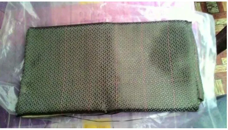
2.0.1.1 Dry Carbon
8
Figure 2.1 Dry Carbon
2.1 THERMOSET RESIN
9
2.1.1 Epoxy
Epoxy is a very versatile resin system, allowing for a broad range of properties and processing capabilities. It exhibits low shrinkage as well as excellent adhesion to a variety of substrate materials.[10] Epoxies are the most widely, used resin materials and are used in many applications, from aerospace to sporting goods. There are varying grades of epoxies with varying levels of performance to meet different application needs. They can be formulated with other materials or can be mixed with other epoxies to meet a specific performance need. By changing the formulation, properties of epoxies can be changed; the cure rate can be modified, the processing temperature requirement can be changed, the cycle time can be changed, the drape and take can be varied, the toughness can be changed, the temperature resistance can be improved. Epoxies are cured by chemical reaction with amines, anhydrides, phenols, carboxylic acids, and alcohols. An epoxy is a liquid resin containing several epoxide groups, such as dglycidyl ether of bisphenol A (DGEBA), which has two epoxide groups. In an epoxide group, there is a three-membered ring of two carbon atoms and one oxygen atom. In addition to this starting material, other liquids such as diluents to reduce its viscosity and flexibilizers to increase toughness are mixed. The curing reaction which is cross-linking takes place by adding a hardener or curing agent. During curing DGEBA molecules form cross links with each other. These cross-links grow in a three-dimensional network and finally form a solid epoxy resin. Cure rates can be controlled through proper selection of hardeners and catalyst. Each hardener provides different cure characteristics and different properties to the final product. The higher the cure rate, the lower the process cycle time and thus higher production volume rates.[5]