DESIGN AND ANALYSIS OF MEMS CAPACITIVE
ACCELEROMETER WITH OPTIMIZED SENSITIVITY
KHAIRUN NISA BT KHAMIL
RESEARCH PROJECT SUBMITTED IN PARTIAL
FULFILLMENT OF THE REQUIREMENTS
FOR THE DEGREE OF MASTER OF ENGINEERING
FACULTY OF ENGINEERING
UNIVERSITY OF MALAYA
KUALA LUMPUR
UNIVERSITI MALAYA
ORIGINAL LITERARY WORK DECLARATION
Name of Candidate: KHAIRUN NISA BT KHAMIL (I.C/Passport No: 850101146334) Registration/Matric No: KGK 110014
Name of Degree: Master of Engineering (Industrial Electronics and Control) Title of Project Paper/Research Report/Dissertation/Thesis (“this Work”):
DESIGN AND ANALYSIS OF MEMS CAPACITIVE ACCELEROMETER WITH OPTIMIZED SENSITYVITY
Field of Study: MICROELECTROMECHANICAL SYSTEM (MEMS) I do solemnly and sincerely declare that:
(1) I am the sole author/writer of this Work; (2) This Work is original;
(3) Any use of any work in which copyright exists was done by way of fair dealing and for permitted purposes and any excerpt or extract from, or reference to or reproduction of any copyright work has been disclosed expressly and sufficiently and the title of the Work and its authorship have been acknowledged in this Work;
(4) I do not have any actual knowledge nor do I ought reasonably to know that the making of this work constitutes an infringement of any copyright work;
(5) I hereby assign all and every rights in the copyright to this Work to the University of Malaya (“UM”), who henceforth shall be owner of the copyright in this Work and that any reproduction or use in any form or by any means whatsoever is prohibited without the written consent of UM having been first had and obtained;
(6) I am fully aware that if in the course of making this Work I have infringed any copyright whether intentionally or otherwise, I may be subject to legal action or any other action as may be determined by UM.
Candidate’s Signature Date
Subscribed and solemnly declared before,
Witness’s Signature Date
Name: Designation:
ABSTRACT
Nowadays, numerous research studies have been done on MEMS based
micro-accelerometer that focuses on optimizing the device sensitivity. With a smaller size
compared to the conventional design of the accelerometer, it weighs lesser, functions
more efficiently which then contributes to cheaper manufacturing cost. The selection of
type and model of the MEMS accelerometer is important before the design parameter
can be determined. The relationship between mass width, beam (length and width) and
the device sensitivity are investigated. After the theoretical analysis has been calculated,
the FEM simulation is then done by constructing three dimensional model structures
and the displacement sensitivity of the device is simulated. The result from the
simulation proved that it matches the theoretical analysis. The optimization analysis
concluded that desired sensitivity can be achieved by adding number of fingers and
adjusting the length of the beam. The optimizing method used in this project is based on
trial and error technique. From the simulation result, the device has a displacement
sensitivity of 3.5301 nm/g which showed that the MEMS accelerometer sensitivity has
been optimized. By using this recommended MEMS capacitive accelerometer, an airbag
deployment system in automobiles with the capability to withstand extensive range of
shock can be designed.
ABSTRAK
Pada masa kini, terdapat banyak kajian dan penyelidikan mengenai pecutan
meter mikro dalam teknologi sistem elektromekanik mikro (MEMS) yang
mengoptimumkan prestasi dengan kaedah peningkatan sensitiviti untuk peranti. Dengan
saiz yang lebih kecil dan padat berbanding dengan reka bentuk konvensional meter
pecutan, meter pecutan mikro adalah lebih ringan, cekap dan seterusnya menjadikan kos
pengeluaran jauh lebih murah. Permilihan struktur model dan jenis meter pecutan
MEMS yang bersesuaian adalah penting sebelum parameter reka bentuk dapat
ditentukan. Hubungan diantara lebar jisim, panjang dan lebar rasuk, sensitiviti peranti
dapat dianalisa. Selepas analisa teori, simulasi FEM membina struktur model tiga
dimensi dan analisasensitiviti anjakan dapat dilakukan. Hasil dari simulasi, analisis dari
teori dapat dibuktikan. Analisis tersebut menunjukkan sensitiviti yang dikehendaki
boleh dicapai dengan penambahan bilangan jari meter pecutan dan menetapkan panjang
rasuk yang bersesuaian. Teknik mengoptimumkan peranti adalah berasaskan kaedah
cuba jaya. Berdasarkan keputusan simulasi, peranti mempunyai sensitiviti anjakan
3.5301 nm/g. Dengan itu, sistem beg udara dalam kereta mempunyai keupayaan untuk
menahan pelbagai kejutan yang direka dengan menggunakan teknologi MEMS meter
pecutan mikro kapasitif yang disyorkan ini.
ACKNOWLEDGEMENT
Alhamdulillah. All praise to Allah s.w.t. Thanks to Allah s.w.t for His blessing
so that I can complete this research project of “Design and Analysis of MEMS
Capacitive Accelerometer with Optimized Sensitivity”. This research project is done as for the requirements to complete the Master of Engineering in University Malaya.
With this opportunity, I would like to express my appreciation to my supervisor,
Assoc. Prof. Dr. Norhayati Soin that helps me with guidance and advice throughout the
entire research. Her experiences in Microelectromechanical system pointed me into the
right direction to conduct my research. I thank her for the thoughtful, perseverance and
trust she has put in me to complete this research.
Next, I would like to thank my sponsor and employer, Kementerian Pengajian
Tinggi Malaysia and Universiti Teknikal Malaysia Melaka for giving me the chance to
further my studies with the Skim Latihan Akademik Bumiputera (SLAB) scholarship.
Most importantly, I would like to thank my husband, Ahmad Nizam B. Isa for
giving me the permission to pursue my studies. I could not thank him enough with all
his helps especially taking care of our kids during the weekends when I went to class
and his patience when I need to do my research. Not to forget, thanks to my family that
helped me taking care of my kids and with the house work while I’m busy with studies
and this project.
I also want to thank my colleagues at Universiti Malaya Norshahida, Nurul Ain,
Suziana for helping with the simulation and giving inputs on how to solve the problem
occurred to complete this research project. Last but not least, my proof read checker,
Shireen Zaki that helps checked the thesis.
TABLE OF
CONTENTS
TITLE i
DECLARATION ii
ABSTRACT ... iii
ABSTRAK ... iv
ACKNOWLEDGEMENT ... v
TABLE OF CONTENTS ... vi
LIST OF FIGURES ... viii
LIST OF ABBREVIATIONS ... x
LIST OF NOMENCLATURES ... xi
CHAPTER 1 ... 13
1.1 Overview ... 13
1.2 Background Studies ... 14
1.3 Structure device design of MEMS capacitive accelerometer ... 15
1.4 Finite element analysis and optimization method ... 16
1.5 Thesis Objectives ... 17
1.6 Scope and Limitation ... 17
1.7 Project Methodology ... 17
1.8 Thesis Outline ... 18
CHAPTER 2 ... 19
2.1 Introduction ... 19
2.2 Literature surveys ... 20
2.3 Principle of operation ... 23
2.4 Device Design ... 26
2.5 Mechanical Suspension ... 28
2.6 Damping and Quality Factor ... 30
2.7 Basic knowledge for capacitive MEMS ... 31
2.7.1 Capacitive Sensing technique ... 31
2.8 Analysis of the device ... 35
2.9 Performance Analysis of the device ... 38
2.9.1 Displacement Sensitivity analysis ... 38
2.9.2 Optimization Analysis ... 41
2.10 Finite Element Modelling tools. ... 42
CHAPTER 3 ... 46
3.1 Introduction ... 46
3.2 Selection of Model Structure ... 47
3.3 Determination of Design Parameters ... 49
3.4 COMSOL Multiphysics® Simulation ... 50
CHAPTER 4 ... 52
4.1 Introduction ... 52
4.2 Simulation Results of Sensitivity Analysis ... 53
4.2.1 Variation of Beam Width (Part a) ... 53
4.2.2 Variation of Beam Length (Part b) ... 55
4.2.3 Variation of Mass Width (Part c) ... 56
4.3 Simulation Results of Optimization Analysis ... 58
4.4 Comparison between Optimized Result with Published models ... 65
CHAPTER 5 ... 67
5.1 Conclusion ... 67
5.2 Recommendation for Future Work ... 68
REFERENCES ... 69
APPENDIX A ... 73
LIST OF FIGURES
Figure 1.1 Airbag system (Brain, 2013) ... 14
Figure 1.2 Accelerometer structure (Lyshevski, 2002)... 16
Figure 2.1 Basic accelerometer (K.H Denishev, 2007) ... 23
Figure 2.2 Schematic of accelerometer (W.C.Wong, 2007) ... 26
Figure 2.3 Differential capacitance of accelerometer (K.Sharma et al 2008) ... 27
Figure 2.4 Type of suspension design model (W.C.Wong, 2007) ... 28
Figure 2.5 Suspension beam structure features (LC, 2008) ... 29
Figure 2.6 Basic capacitance model of displacement sensors (Stephen Beeby, 2004) ... 31
Figure 2.7 Schematic Diagram of capacitive MEMS (Xiong, 2005)... 32
Figure 2.8 One of the COMSOL’s examples (COMSOL, 2013) ... 43
Figure 3.1 Flowchart of project ... 47
Figure 3.2 Side view of the overall device... 48
Figure 3.3 Top view of the overall device ... 48
Figure 3.4 Flowchart of COMSOL Multiphysics® simulation process ... 51
Figure 4.1 The displacement sensitivity versus beam width ... 53
Figure 4.2 The displacement sensitivity versus beam length ... 55
Figure 4.3 The displacement sensitivity versus Mass Width ... 56
Figure 4.4 Sensitivity versus Beam Length for each of number of fingers ... 59
Figure 4.5 Stress versus Acceleration ... 62
Figure 4.6 Top View Stress Simulation ... 63
Figure 4.7 Side View Stress Simulation ... 63
Figure 4.8 Capacitance versus Acceleration for Original Model and Optimized Model 64
LIST OF TABLES
Table 2.1 Summary of other researchers Capacitive Accelerometer studies
(W.C.Wong, 2007) ... 22
Table 2.2 Length of proof mass, Lm for number of fingers, Nsf ... 41
Table 2.3 Physics Groups in the Model Wizard (COMSOL, 2013) ... 44
Table 3.1 Structure Label and Dimension ... 49
Table 3.2 Material Properties ... 49
Table 3.3 Design Specification ... 50
Table 4.1 The Percentage differences between each of the Beam Width ... 54
Table 4.2 Percentage difference between each of the Beam Length ... 55
Table 4.3 Percentage difference between each of the Mass Width ... 57
Table 4.4 Calculated data for each number of fingers and Beam Length. ... 58
Table 4.5 Percentage differences between the sensitivity for each number of fingers and beam length ... 60
Table 4.6 Percentage of error between Analytical and Simulated result for both Optimized and Original models... 61
Table 4.7 Percentage of increase between Analytical and Simulated result for both Optimized and Original models... 62
Table 4.8 Stress Analysis ... 63
Table 4.9 Benchmarking to other researcher's finding ... 66
LIST OF ABBREVIATIONS
MEMS Microelectromechanical systems
SRS Supplemental Restraint System
FEA Finite Element Analysis
IC Integrated Circuit
FEM Finite Element Modelling
ODE Ordinary differential Equation
MOSFET Metal Oxide Semiconductor Field Effect Transistor
LIST OF NOMENCLATURES
C: Capacitance
d: Distance
ε, εo : Electric Constant
A: Area
m: Mass
Ms: Movable Mass
Kfold, Ks: Spring Constant
aext: External Acceleration
D: Damping Coefficient
x: Displacement
f0, ��: Resonant Frequency
Q: Quality Factor
Vx: Voltage Output
Nf: Total Sensing Finger Number
n
eff : Effective Viscosity of Airl
b: Beam LengthW
b: Beam Widtht: Thickness
E: Young’s modulus
S: Join Area Between Mass and The Fingers
Vm: Voltage Modulation
d0: Stationary Gap of the Capacitance
�: Frequency of Modultaion voltage
t0: Time of operation
Fd: Electrostatic Force
V0: Voltage Input
Wm : Proof Mass Width
Lm: Proof Mass Length
Nsf: Total of Sensing Finger
Nff : Total of Fixed Finger
Wf: Fingers Width
Lf: Fingers Length
Finertial: Inertia Force
Ktotal: Total of Spring Constant
�: Density of Polysilicon
Ib: Inertial Momentum
Sd: Displacement Sensitivity
Sc: Capacitance Sensitivity
CHAPTER 1
INTRODUCTION
1.1 Overview
This chapter aims to discuss the background of the Microelectromechanical
systems or MEMS with the outline of the thesis which presented as follows:
• Background studies
• Structure device design of MEMS capacitive accelerometer
• Finite element analysis and improvisation method
• Thesis objective
• Scope and limitation
• Thesis outline
Nowadays, numerous research studies are made on MEMS based
micro-accelerometer that focus on optimizing the device sensitivity. With a smaller size
compared to the conventional design of the accelerometer, it weighs lesser, functions
more efficiently which then contributed to cheaper manufacturing cost..
MEMS accelerometers can be found used in most of our everyday life items
which ranging from telecommunication to health and safety like airbag deployment
systems used in vehicles. By detecting the negative acceleration of the automobile,
accelerometers are the sensor to use. These sudden changes of the negative acceleration
are depend on the changes to the types of the sensor that will be used in this project
which is the capacitance.
1.2 Background Studies
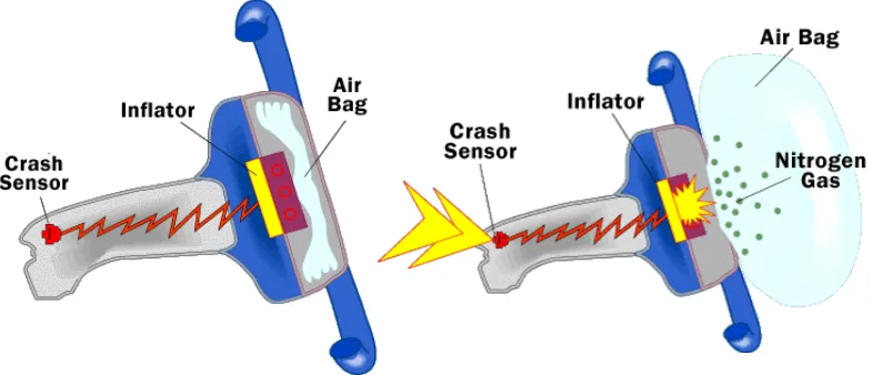
In most automobiles these days, airbag has become the most important features
due to its safety purposes. For Toyota Motor Corporation, the Supplemental Restraint
System (SRS) of the Airbag System increases vehicle user’s safety and aimed to
enhance the seatbelt method (Toyota Motor Corporation, 2013).
For SRS airbag to be deployed, the amount of the collision needed is calculated
for the sensor to sense the impact. The time taken for the airbag to complete deploying
must be around 0.03 seconds as the human eye can blink from 0.1 to 0.3 seconds which
made the completion period took 0.1 seconds. After that, the airbag deflated.
The deployed and deflated process occurred rapidly where the vehicle’s user
have no chance to do anything. This shows that the sensitivity of the sensor used in the
airbag system is vital since it is served safety purposes.
Figure 1.1 Airbag system (Brain, 2013)
1.3 Structure device design of MEMS capacitive accelerometer
The interface of capacitance sensors have some remarkable features which are
very sensitive and not easily effected by temperature. This shows why the capacitance is
commonly chosen for accelerometer (Andrejašic, 2008).
�= �0�� �
(1.1)
Referring to equation 1.1, εoε is permittivity, C is equivalent to Capacitance,
distance as d and the area as A. When the housing (main part for the capacitive
accelerometer) that sometimes can be referred as seismic mass or proof mass moved the
“comb-like” part back and forth so that the acceleration can be calculated. As the result
from the movement of the center section, the fingers on the accelerometer structure
made up a differential capacitance and allowing the current to flow (G.H.Y. I. Lee,
2005).
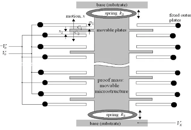
�= ��� ��0��
(1.2)
The voltage of the proof mass is the output voltage, Vxand x is the displacement. While
the spring constant will be Ksand the mass is m. Therefore, the acceleration can be
found (Sharma et al., 2008) .
Figure 1.2 Accelerometer structure. The spring’s constant is attached to proof mass at substrate where it moved up and down. From the movable and fixed plates, the capacitor is determined (Lyshevski, 2002)
1.4 Finite element analysis and optimization method
By using the Finite Element Analysis (FEA), the product can be designed and
analyzed virtually where the computer simulation predicts a detailed outcome of the
design before manufacturing it. This technique can save the manufacturing cost without
even manufactured the real design over and over again. Three dimensional is commonly
used to see a more realistic and accurate effects (Widas, 1997). The testing will able to
show how much the device can take the stress using a certain material or how much the
displacement is given at certain amount of force at each of the axis and so on. FEA lets
engineers understand the product design entirely and verify the theoretical method.
Through FEA, optimization method for the design can be easily done. For this
research project, trial and error method is used by re-designing the published structure
to get higher sensitivity of the device.
1.5 Thesis Objectives
The objective of this project is to optimize MEMS accelerometer structure by
enhancing the device sensitivity.
1.6 Scope and Limitation
Even though the micromachined of the device with certain parameter can
certainly increase the sensitivity, the structure of the device only focuses on simulation
of the design and also the analytical analysis.
As for the simulation part, it will cover the Solid Mechanic studies to check the
displacement of the device and how much stress the accelerometer can withstand.
Another study is the Electrostatic Studies where the capacitance can be achieved.
1.7 Project Methodology
In general, methodology used in this project is shown in Figure 3.1. It can be
divided into three main parts, which are the literature reviews that consist of the
background studies and the theoretical research and analysis. Next is the selection of the
model structure. After the right type and model structure is chosen, the design
parameter can be determined. The Finite Element simulation comprises the
construction of three dimensional model structures and the analysis of the device’s
displacement sensitivity. These simulations were first made using the published model’s
dimension. After the simulations confirmed the theoretical analysis, the next simulation
is to optimize the device sensitivity after the structure is re-designed. Last but not least,
to document the whole process in a report. The project methodology will be explained
in detail in Chapter 3.
1.8 Thesis Outline
This thesis comprises five chapters which includes Introduction in Chapter 1,
Literature Review in Chapter 2, the project Methodology in Chapter 3, Results and
Discussion in Chapter 4 and last but not least the Conclusion in Chapter 5.
Chapter 1 provides the overview of the background studies of the example
accelerometer, its structure and the finite element analysis used. The objective and
scopes of the project are also explained in this chapter.
Chapter 2 will present the literature review of MEMS accelerometer and all the
concise theoretical analysis used in this project. This chapter contains ten main parts,
which are the literature suvey, principles of operation, the device’s design, mechanical
suspension, damping and quality factor, basic knowledge on capacitive MEMS, analysis
of the device, performance analysis of the device and the finite element analysis tools.
In Chapter 3, the methodology of the project presented will be on the selection
of the model structure chosen from the published model, determination of design
parameters and the FEM simulation process.
As for Chapter 4, the results will be presented in graph and in tables. Each result
will be elaborated and discussed in detail.
Finally, the thesis will be finished with conclusions in Chapter 5 that
summarized the project methods and results and the potential recommendation for
future improvement.
CHAPTER 2
LITERATURE REVIEW
2.1 Introduction
MEMS (Micro Electromechanical System) has become an emerging technology
that covers from house appliance to automotive and even in the medical industry. The
remarkable development with MEMS is initiated from the integrated circuit
technologies and then evolved into a highly functional system in miniaturized version.
MEMS sensor comes from an input of mechanical signal which is converted using an
interface circuit to a corresponding electrical signal that is used to produce the required
control function (B.P. Gogoi (2002).
This incorporation between MEMS sensor with the help of the interface circuit
can be done using silicon or packaged it completely. Most MEMS devices are prepared
from silicon wafer which are similar to integrated circuit (IC) where MEMS fabrication
also shares the same standard processes like etching, photolithography oxidation,
diffusion and deposition.
2.2 Literature surveys
As mention in previous chapter, the model structure are based on the published
model that similar to Analog Device Inc, ADXL 150 accelerometer (Sharma et al.,
2008). Before optimizing the accelerometer, several researchers model are also
investigated but the scope of the studies only focus on capacitive accelerometer. In
(Chae, Kulah, & Najafi, 2002), the comb finger type of accelerometer was optimized
using analytical derivation and the model structure is novel design with a large
thickness due to DRIE fabrication. For (Lüdtke, Biefeld, Buhrdorf, & Binder, 2000), the
capacitance sensitivity are investigated using only basic comb finger type of
accelerometer with six sensing fingers. While in (Luo, Zhang, Carley, & Fedder, 2002),
the model structure are based on ADXL 202 from Analog Devices Inc. and the scope
focusing on electrically isolated multimetal routing on microstrctures and minimizing
parasitic capacitance. This factors created a full-bridge capacitive sensors and an
integration to increase transducer sensitivity. The other researchers that also using the
same model structure as (K.Sharma et al 2008) is (Benmessaoud & Nasreddine, 2013)
that uses the same optimization method but different FE tool.
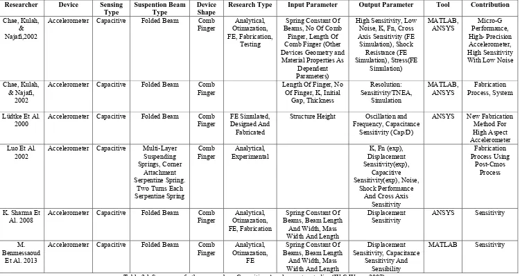
The review of the existing MEMS capacitive accelerometer analysis has been
summarized in Table 2.1. This comb finger type capacitive accelerometer proved in
each of the research studies to be most successful type accelerometer since it gives high
sensitivity in capacitance due to its large sensing area. However, the researches on
comb finger type accelerometer are limited. By tracing back to the application of comb
finger type device, this design has been used in actuator for a long time (W.C.Wong,
2007). The study successes in comb finger as used in actuator can be used as the
reference for comb finger type as being used in accelerometer. Regardless of what type
being used in accelerometer or actuators, resonant frequency and the variation of the
structure in comb finger type are the interested parameters that are being considered in
the structural analysis and to optimize the sensitivity.
Thus, the current work tries to fill the absence in the above study and the aim is
to develop a methodology comprising the analytical and numerical study for structural
analysis and optimization of the sensitivity for comb finger type accelerometer. In this
project, the finding will be referred closely to simulated result of (Sharma et al, 2008)
and (Benmessaoud & Nasreddine, 2013) since both published model are also optimized
the device displacement sensitivity (Benmessaoud & Nasreddine, 2013). The
displacement sensitivity is an important element of the sensing process, and it is part
of the open-loop gain of the sensor. So, it is a strong inverse relationship between
sensitivity and bandwidth for any class of sensors (Bernstein, 2003).
Researcher Device Sensing
Research Type Input Parameter Output Parameter Tool Contribution
Chae, Kulah, & Najafi,2002
Accelerometer Capacitive Folded Beam Comb
Finger Otimazation, Analytical, FE, Fabrication,
ANSYS Performance, Micro-G High- Precision
Accelerometer Capacitive Folded Beam Comb
Finger Length Of Finger, No Of Finger, K, Initial Gap, Thickness
Resolution: Sensitivity/TNEA,
Simulation
MATLAB,
ANSYS Process, System Fabrication
Lüdtke Et Al.
2000 Accelerometer Capacitive Folded Beam Finger Comb FE Simulated, Designed And Fabricated
Structure Height Oscillation and Frequency, Capacitance
2002 Accelerometer Capacitive Multi-Layer Suspending Springs, Corner
Finger Experimental Analytical, Displacement K, Fn (exp), Sensitivity(exp),
Al. 2008 Accelerometer Capacitive Folded Beam Finger Comb Otimazation, Analytical, FE, Fabrication
Sensitivity ANSYS Sensitivity
M. Benmessaoud
Et Al. 2013
Accelerometer Capacitive Folded Beam Comb
Finger Otimazation, Analytical, FE
Table 2.1 Summary of other researchers Capacitive Accelerometer studies (W.C.Wong, 2007)
2.3 Principle of operation
Interface in capacitance sensor have some great features where it can function
equally as an actuator and a sensor. It is highly sensitive but naturally unaffected to
Curretemperature (Stilson, 1996).
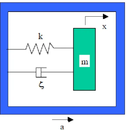
To understand the operation of accelerometer is by simply using the principle of a mass
spring system which is the second order mass-spring-damper system (Vijayakumar S,
2011).
��.� 2� ��2 +�.
��
��+��.�=��.����
(2.1)
given the spring constant, ��, the damping coefficient as D, the movable mass as Ms
and the external acceleration as ����.
Figure 2.1 Basic accelerometer (K.H Denishev, 2007)
If the equation (2.1) changes to transfer function of second order using the Laplace
because it is inversely proportional to each other.
The total of the spring constant that has been extended or retracted at a certain
displacement will give a reinstating force which is relative to:
� =���
(2.3)
In equation 2.3, Ks, the spring constant and displacement, x is proportional to force, F
(Sharma et al.). There’s another main principle that will show a force functioning on a
mass with acceleration, Newton's second law of motion:
�= ���
(2.4)
This mass is attached to a spring and when it goes into acceleration, then by Newton's
law, there will be a resultant force equal to Msa.


