UNIVERSITI TEKNIKAL MALAYSIA MELAKA
Comparative Study of End-Mill Performance between Straight and
Spiral Flute
This report is submitted in accordance with requirement of the Universiti Teknikal
Malaysia Melaka (UTeM) for the Bachelor Degree of Manufacturing Engineering (Manufacturing Process) with Honours.
by
AHMAD MUSLI BIN OSMAN
Faculty of Manufacturing Engineering
UTeM Library (Pind.1/2007)
UNIVERSITI TEKNIKAL MALAYSIA MELAKA
BORANG PENGESAHAN STATUS LAPORAN PSM
TAJUK: COMPARATIVE STUDY OF END-MILL PERFORMANCE BETWEEN STRAIGHT AND SPIRAL FLUTE
SESI PENGAJIAN: 2008/09 Semester 2
Saya AHMAD MUSLI BIN OSMAN
mengaku membenarkan laporan PSM / tesis (Sarjana/Doktor Falsafah) ini disimpan di Perpustakaan Universiti Teknikal Malaysia Melaka (UTeM) dengan syarat-syarat kegunaan seperti berikut:
1. Laporan PSM / tesis adalah hak milik Universiti Teknikal Malaysia Melaka dan penulis.
2. Perpustakaan Universiti Teknikal Malaysia Melaka dibenarkan membuat salinan untuk tujuan pengajian sahaja.
3. Perpustakaan dibenarkan membuat salinan laporan PSM / tesis ini sebagai bahan pertukaran antara institusi pengajian tinggi. atau kepentingan Malaysia yang termaktub di dalam AKTA RAHSIA RASMI 1972)
DECLARATION
I hereby declare this report entitled “COMPARATIVE STUDY OF END-MILL PERFORMANCE BETWEEN STRAIGHT AND SPIRAL FLUTE” is the result of my own research except as cited in the references.
Signature :
APPROVAL
This report is submitted to the Faculty of Manufacturing Engineering of UTeM as a partial fulfillment of the requirements for the degree of Bachelor of Manufacturing Engineering (Manufacturing Process) with Honours. The member of the supervisory committee is as follow:
……….
PROF. DR. MOHD. RAZALI BIN MUHAMAD (PSM Supervisor)
………. ENCIK NIZAM BIN ABDUL RAHMAN
(PSM Co-Supervisor)
………. ENCIK SYAFIK BIN JUMALI
ABSTRACT
Nowadays, there are many studies done on the effects of the cutting tool and other parameters to the surface finish of the product. There are also studies done to study the effect of the machining parameters on the cutting tool itself. Those studies were conducted to find the suitable parameters in order to optimize the metalworking process. In metalworking industries, good surface finish is one of the criteria that the product should have. Therefore, the study on chatter stability has carried out widely by studying the effect of end mill used in the metalworking process such as helical ball end end-mill, and straight end-mill on the product being machined. There is some studies that are also study the effect of the straight flute end mill and spiral
ABSTRAK
Dewasa ini, terdapat banyak kajian yang dilakukan berkaitan mata alat pemotong dan pelbagai parameter lain yang mungkin memberi kesan terhadap permukaan produk yang dihasilkan. Terdapat juga kajian yang dilakukan terhadap parameter-parameter yang mungkin memberi kesan terhadap mata alat pemotong itu sendiri. Semua kajian ini dilakukan untuk mencari parameter yang optimum bagi tujuan pemesinan. Dalam industri pemesinan, hasil akhir pada permukaan produk adalah suatu kriteria yang perlu dicapai. Maka dengan itu, kajian tentang kesan kestabilan geligis terhadap produk yang dihasilkan banyak dilakukan terutama yang berkaitan mata alat pemotong. Terdapat juga kajian yang dilakukan terhadap kesan kestabilan geligis mata alat pemotong yang lurus serta yang berlengkuk kepada produk yang dimesin. Walaubagaimanapun, tiada perbandingan khusus yang dilakukan terhadap pencapaian atau prestasi memotong antara mata alat pemotong yang lurus dengan yang berlengkuk. Diakhir kajian ini, rumusan tentang prestasi mata alat pemotong yang terbaik antara keduanya akan dinyatakan setelah perbandingan dilakukan dengan merujuk graf yang dibentuk melalui data-data yang dikumpul melalui eksperimen yang telah dijalankan. Berdasarkan data yang diperolehi, mata alat pemotong berlengkuk atau berpilin menunjukkan prestasi yang lebih baik jika dibandingkan dengan prestasi mata alat pemotong yang berpilin. Berdasarkan kajian
ini juga didapati bahawa mata alat pemotong berpilin 15° menunjukkan prestasi yang
lebih stabil berbanding mata alat pemotong berpilin 30° dari segi daya pemotongan,
DEDICATION
ACKNOWLEDGEMENT
TABLE OF CONTENT
2.5.3 Multiple Flute End Mills 11
2.5.4 Roughing End Mills 11
2.6 Type of Relieve Cutters 12
2.6.1 Spiral Flute End Mill 12
2.6.2 Straight Flute End Mill 13
2.7.1 Carbide End Mill 14
3.2 Gantt chart and Methodology Flow Chart 23
3.3 Discussion and Conformation on the Project Title 25 3.4 Literature Review of the Project Title 25 3.5 Selection of Machined and Material in used 25
3.5.1 Milling Machines 25
3.5.1.1Specification of Turret Milling Machine 26
3.5.2 Cutting tool 27
3.5.2.1Tool Grinder Machine 28
3.5.2.2Specification of CNC Tool Grinder Machine 28
3.5.3 Workpiece material 29
3.6 Variable and constant parameters identification 30
3.7 Conduct of experiment 31
3.7.1 Milling Machine Operation Procedures 31 3.7.2 Tool wear experiment procedures 32 3.8 Data Collection and Data Analysis 33 3.8.1 Equipment used for data analysis 33 3.8.1.1Ziess Microscope Axioskop Two Mat and its setup procedures 33
3.8.1.2Cutting Force Measurement 35
3.8.1.3Surface Roughness Measurement 36
4. RESULT AND DISCUSSION 40
4.3.1 Performances difference in-terms of Cutting Forces 52 4.3.2 Performances difference in-terms of Surface Roughness 54 4.3.3 Performances difference in-terms of Tool Wear 56
5. CONCLUSION AND RECOMMENDATION 58
5.1 Conclusion 58
5.2 Recommendations 59
REFERENCES 60
APPENDICES
A Surface roughness data for 1st experiment. B Surface roughness data for 2nd experiment. C Surface roughness data for 3rd experiment. D Surface roughness data for 4th experiment. E Surface roughness data for 5th experiment.
F Cutting force data for 1st experiment (0° and 15° flute).
G Cutting force data for 1st experiment (30° flute) and 2nd experiment (0° flute). H Cutting force data for 3rd experiment (0° and 15° flute).
I Cutting force data for 3rd experiment (30° flute) and 4th experiment (0° flute). J Cutting force data for 4th experiment (15° and 30° flute).
LIST OF TABLES
3.1 Gantt chart of PSM 23
3.2 Turret Milling Machine Specification 26 3.3 CNC Tool Grinder Machine Specification 28
3.4 Parameters Specification 31
3.5 Data Collection Table 39
4.1 Data Collection 41
LIST OF FIGURES
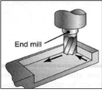
2.1 End milling operation. 6
2.2 Three common shapes ground on end mill. 7
2.3 Milling cutter nomenclature. 8
2.4 Coated HSS roughing end mill. 12
2.5 Force acting in the cutting zone during two dimensional cutting. 16 2.6 A wide range of parameters influence these wear and failure patterns. 18 2.7 Interface of a cutting tool (right) and chip (left) in machining plain-
carbon steel. 19
2.8 Illustration of Stylus Profilometer. 21
3.1 Methodology flow chart. 24
3.2 Turret milling machine. 26
3.3 Tungsten Carbide End Mills. 27
3.4 MICHAEL DECKEL CNC Tool Grinder Machine. 28 3.5 Carbon Steel AISI 1045 as workpiece material. 29 3.6 BOMAR Horizontal Bandsaw Machine. 29 3.7 The shape and dimensions of the specimens for the experiments. 30 3.8 Ziess Microscope Axioskop Two Mat. 34 3.9 Axioskop imager has wide ranges of high contrast objectives. 34
3.10 Kistler DynoWare Dynamometer. 35
3.11 Experimental setup to measure cutting forces 36 3.12 Standard terminology and symbol to describe surface finish on
machined surfaces. 37
3.13 Example of calculation for Ra and Rq roughness height. 38
3.14 The Stylus Profilometer. 38
4.1 Graph of Cutting Forces between 0° and 15° of End-mill’s Helix Angle
Flute. 42
4.2 Graph of Cutting Forces between 0° and 30° of End-mill’s Helix Angle
Flute. 43
4.3 Graph of Cutting Forces between 15° and 30° of End-mill’s Helix
4.4 Graph of Surface Roughness between 0° and 15° of End-mill’s Helix
Angle Flute. 45
4.5 Graph of Surface Roughness between 0° and 30° of End-mill’s Helix
Angle Flute. 46
4.6 Graph of Surface Roughness between 15° and 30° of End-mill’s Helix
Angle Flute. 47
4.7 Samples of tool wear occurred after 130 mm cutting distance. 48 4.8 Graph of Tool Wears between 0° and 15° of End-mill’s Helix Angle
Flute. 49
4.9 Graph of Tool Wears between 0° and 30° of End-mill’s Helix Angle
Flute. 50
4.10 Graph of Tool Wears between 15° and 30° of End-mill’s Helix Angle
Flute. 51
4.11 Graph of Cutting Forces between 0°, 15° and 30° of End-mill’s Helix
Angle Flute. 52
4.12 Graph of Surface Roughness between 0°, 15° and 30° of End-mill’s
Helix Angle Flute. 54
4.13 Graph of Tool Wears between 0°, 15° and 30° of End-mill’s Helix
LIST OF ABBREVIATIONS
UTeM - Universiti Teknikal Malaysia Melaka V - Cutting Speed
CHAPTER 1
INTRODUCTION
1.1 Project Background
End Milling is an important and common machining operation because of its
versatility and capability to produce various profiles and curved surfaces. End-mill has either a straight shank or a tapered shank and is mounted into the spindle of the milling machine. End-mills may be made of high speed steels (HSS), carbide or with carbide inserts, similar to those for face milling. The cutter usually rotates on an axis perpendicular to the workpiece surface. End milling can produce a variety of surfaces at any depth, such as curved, stepped, and pocketed. The cutter can remove material on both its end and its cylindrical cutting edges.
End-mills have greatly improved since the days of carbon-steel cutting tools. High-speed steels (HSS) cutting tool are considered old today, yet still maintain a very importance place in the metal-cutting industry (Krar, et al. , 2005). In the industry today, cutting tool material must have properties that can provide efficient metal removal rates for the machining application. All of variables involved such as part shape, machine condition, workpiece material, relative wear resistance of the cutting tool, toughness, cutting forces and others influence the decision on the type of cutter that should be selected.
Therefore, many researches have been done to improve metal cutting performance
and ease the selection of the parameters in metal cutting. One of the research areas done on end mill was on relieve cutter design, especially on helical flute end-mills.
influence of spiral and straight flute in milling operation. They are the analytical prediction of chatter stability conditions for multidegree of freedom systems in milling that been conducted and the analysis of the influence of mill helix angle on chatter stability have been done by Zatarain, et al. (2006). Both studies investigate only on the influences of spiral flute end-mills and straight flute end-mills to the milling process on the chatter stability. However, those studies do not provide comparison of performance between spiral and straight flute in milling operation in terms of cutting force, surface roughness and tool wear. Thus, this study is carried out to gain those information which can be used to improve machining performance especially in end-mills machining operations.
1.2 Problem Statement
There are two main problems that lead to the study and investigation on the comparison of end-mill performance between straight and spiral flute. Firstly, based on published studies spiral flute end mill gives smoother cutting action and chatter stability in machining process which should contributes to the finer surface finish. However, there is no study been done to compare performance of straight and spiral
flute end mill to validate the assumptions. This study, is trying to prove or disprove that assumption. Other than that, very little study has been done on the influences of spiral and straight flute end-mills in the metalworking operation. This study will
1.3 Objectives
The main purposes of this project are:
To determine the performance differences in terms of surface roughness,
cutting force and tool wear between end-mill with straight flute and that of with spiral flute.
To compare and identify the best end-mill flute design, between straight flute and spiral flute, with respect to overall machining performance.
1.4 Project Scope
The experiment will be conducted using conventional milling and vertical type of milling machine. Both straight flute end-mill and spiral flute end-mill will be used to machine the mild steel as the workpiece material. In this experiment, both types of milling cutter are made from Tungsten Carbide materials which are four flutes type of end-mills. The feed rate and depth of cut will be kept constant for all
1.5 Report Structure
Overall this report is divided into six chapters. The first chapter is mainly
CHAPTER 2
LITERATURE REVIEW
2.1 Milling
Milling is a process in which a rotating cutter removes material while travelling
along various axes with respect to the workpiece. Milling machines are machines tools used to produce one or more machined surfaces accurately on a piece of material, which is called workpiece. This process is done by one or more rotary milling cutters having single or multiple cutting edges. The workpiece is held securely on the work table of the machine or in a holding device clamped to the table. It is then brought into contact with a revolving cutter (Krar et al., 2005).
2.2 End Mill
End mill is the cutter that is used in milling operations. It has either a straight shank (for small cutter sizes) or a tapered shank (for larger cutter sizes) and is mounted into the spindle of the milling machine. End mills may be made of high-speed steels or with carbide inserts. The cutter usually rotates on an axis perpendicular to the workpiece surface, and it also can be tilted to machine tapered or curved surfaces.
End mills are available with hemispherical ends (ball nose mills) for the production of sculptured surfaces, such as on dies and molds. Hollow end mills have internal cutting teeth and are used to machine the cylindrical surface of solid, round
workpieces. End milling can produce a variety of surfaces at any depth, such as curved, stepped, and pocketed. The cutter can remove material on both its end and its cylindrical cutting edges. Vertical spindle and horizontal spindle machines, as well as machining centers, can be used for end milling workpieces of various sizes and shapes.
2.3 End Mill Form
End mills can be ground into required shapes but, the most common type of end
mills is flat bottom end mill, end mill with a full radius (often called a ball nose end mill) and an end mill with a corner radius (often called a bull nose end mill).
Every type of end mill is used for a specific type of machining operation. Standard flat end mils are used for all operations requiring a flat bottom and sharp corner between the wall and the bottom. Meanwhile, a ball nose end mill is used for 3D machining on various surfaces, and a bull nose end mill is used for either 3D work, or flat surfaces that require a corner radius between the wall and the bottom (Krar et al 2005).
2.4 End Mill Features
As far as metal cutting action is concerned, the pertinent angles on the tooth are those
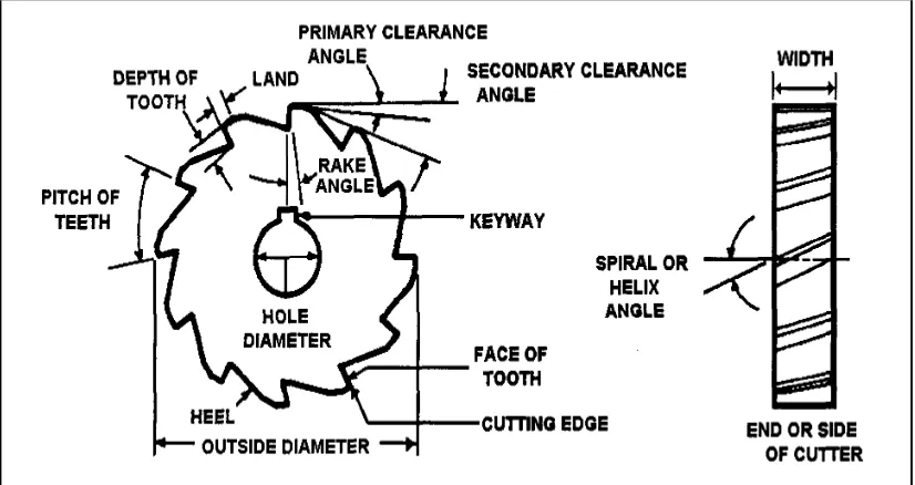
that define the configuration of the cutting edge, the orientation of the tooth face, and the relief to prevent rubbing on the land. The terms defined below and illustrated in Figures 2.3 are important and fundamental to milling cutter configuration.
Figure 2.3: Milling cutter nomenclature (Milling Machine, Anon p.8-3)
Outside Diameter: The outside diameter of a milling cutter is the diameter of a circle passing through the peripheral cutting edges. It is the dimension used in conjunction with the spindle speed to find the cutting speed (SFPM).
Root Diameter: The root diameter is the diameter of the circle passing tangent to the bottom of the fillet.
Tooth: The tooth is the part of the cutter starting at the body and ending with the peripheral cutting edge. Replaceable teeth are also called inserts.
Tooth Face: The tooth face is the surface of the tooth between the fillet and the cutting edge, where the chip slides during its formation.
Land: The land is that part of the back of the tooth adjacent to the cutting edge which is relieved to avoid interference between itself and the surface being machined. A raised land permits numerous resharpenings before a secondary clearance has to be ground.
Gash Angle: The gash angle is measured between the tooth face and the back of the tooth immediately ahead.
Fillet: The fillet is the radius at the bottom of the flute, provided to allow chip flow and chip curling. The terms defined above apply primarily to milling cutters, particularly to plain milling cutters. In defining the configuration of the teeth on the cutter, the following terms are important.
most of the metal. It corresponds to the end cutting edge on single point tools.
Relief Angle: The peripheral relief angle is the angle between the surface formed by the land and a tangent to the cutter outside circle passing through the cutting edge in a diameter plane. It is to prevent the land from rubbing on the surface of the work being cut. Relief and clearance are measured in degrees or in radial fall in inches at a certain specified distance back of the cutting edge on the land. For this latter measurement, a dial indicator may be used to measure the radial fall in thousandths of an inch from the outside or cutting edge diameter back of the cutting edge.
Clearance Angle: The clearance angle is provided to make room form chips, thus forming the flute. Normally two clearance angles are provided to maintain the strength of the tooth and still provide sufficient chip space.
Radial Rake Angle: The radial rake angle of a milling cutter is the angle formed in a diameter plane between the face of the tooth and a radial line passing through the cutting edge. This may be positive, negative, or zero degree.