This content has been downloaded from IOPscience. Please scroll down to see the full text.
Download details:
IP Address: 103.26.74.254
This content was downloaded on 19/12/2013 at 01:41
Please note that terms and conditions apply.
View the table of contents for this issue, or go to the journal homepage for more
Modelling and validation of magnetorheological brake
responses using parametric approach
Zainordin A Z1,a, Abdullah M A2and Hudha K3
1
LectPoliteknik Sultan Haji Ahmad Shah, Kuantan
2
Faculty of Mechanical Engineering, Universiti Teknikal Malaysia Melaka, Malaysia
3
Faculty of Mechanical Engineering, Universiti Pertahanan Nasional Malaysia, Malaysia
E-mail: [email protected]
Abstract. Magnetorheological brake (MR Brake) is one x-by-wire systems which performs better than conventional brake systems. MR brake consists of a rotating disc that is immersed with Magnetorheological Fluid (MR Fluid) in an enclosure of an electromagnetic coil. The applied magnetic field will increase the yield strength of the MR fluid where this fluid was used to decrease the speed of the rotating shaft. The purpose of this paper is to develop a mathematical model to represent MR brake with a test rig. The MR brake model is developed based on actual torque characteristic which is coupled with motion of a test rig. Next, the experimental are performed using MR brake test rig and obtained three output responses known as angular velocity response, torque response and load displacement response. Furthermore, the MR brake was subjected to various current. Finally, the simulation results of MR brake model are then verified with experimental results.
1. Introduction
X-By-Wire is one of the system that had potential to improve performance by minimized the number of part used in the system. Usually, by-wire systems have been employed in several segments such as steering system, suspension system, braking system and medical equipments [1-8]. MR brake has introduced as an actuator of brake-by-wire system in automotive industries. MR brake employs with MR fluid where this fluid solidifies once applied with magnetic field. This fluid is also known as smart fluid where it solidifies by increasing the strength of magnetic. Once the fluid is free from magnetic field, it represents as a Newtonian fluid behaviour. The MR brake consists of a rotating disc immersed with Magnetorheological Fluid (MR fluid) in an enclosure of an electromagnetic coil. MR fluid is developed using micron sized suspensions measured between 20-50 microns [9-10]. The rheological behaviour of MR fluid is similar with the carrier fluid when there is no external field is occurred in the fluid [11-12].
simulations involving magnetostatic, fluid flow and heat transfer analysis [14]. MR fluid selection for MR brake application, such as magnetic circuit design and torque requirements for automotive application was also studied. Karakoc et al. (2008) focussed on the investigation of practical MR brake design criteria such as material selection, sealing, working surface area, viscous torque generation and MR fluid selection for basic automotive braking system [15]. Additionally, Tan et al.
(2007) studies braking response of inertia/load by using an electro-rheological (ER) brake for ER-robotic application in term of ER braking velocity response in order to halt the robot arm rapidly [16]. In 2009, Nam and Ahn (2009) is proposed the new structure of MR brake with the waveform boundary of rotary disk that generated more resistance torque compare to the conventional MR brake [17]. Furthermore, the MR brake system had been implemented to other application such as joystick and prosthetic knee [18, 4].
The outline of this paper is as follows. In section I, brief introduction on the current research of MR brake. Section II represents the experimental facilities and continued with mathematical model of MR brake with test rig in Section III. Section IV describe the model validation between simulation and experimental at constant loads. Finally, the conclusion of this work is presented in Section VII.
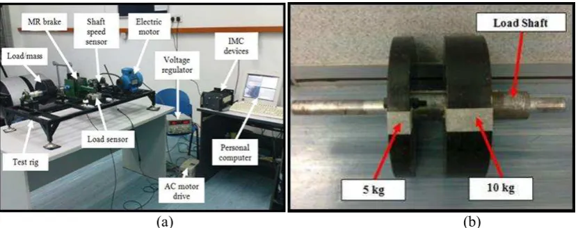
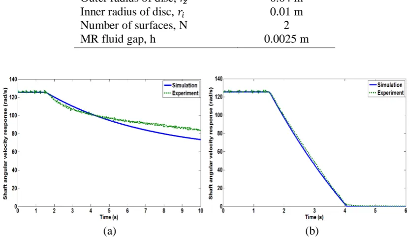
2. Experimental Apparatus
Figure 1(a) shows the testing equipment used in the experiment with the load of 50 N and 100 N that shown in Figure 1(b). The inertia load will be attached to the load shaft and coupled with brake shaft to generate a constant or falling load that resultant the net torque produce by MR brake. The function of AC electric motor is to drive the MR brake shaft to desired velocity where it is coupled to the input shaft/rotor of MR brake via pulley an A-type V-belt.
(a) (b)
Figure 1. a) Mechanical assembly of the MR brake test rig, and b) Load
The speed from the motor is transmitted to the MR brake shaft using belt tensional and well fitted beside the electric motor. The pulley shaft is connected to the MR brake shaft using jaw coupling and same concept also was applied at the load shaft. The pulley shaft and load shaft used a pillow block bearing to support the rotating shaft where the inner bearing will allow the shaft to rotate in free direction. The MR brake housing is coupled to a load cell via an arm of length of 238 mm. In this equipment, the load cell is employed to measure the braking torque. The load cell was calibrated at 1V: 53.4 Nm and the maximum torque measured using this sensor is 534 Nm. Next, the load cell is connected with bridge amplifier as the signal conditioning. Meanwhile, the rotational speed of the MR brake shaft was measured by using an ABS speed sensor.
The MR brake test rig is equipped with an I/O device for data processing. Next, the Integrated Measurement and Control (IMC) device provides signal processing of the sensory system. The IMC device that is only capable to received analogue voltage signal. Then, the signals are digitally processed and stored in a personal computer using FAMOS control software. IMC device is connected
to a personal computer using NetBEUI protocol. A DC power supply manufactured by GW-INSTEK is used to supply electric currents to the MR brake electromagnetic coil. All the measured data are displayed in Personal Computer (PC) for the further analysis.
Mathematical Model
The characteristics of MR fluid can be described by using a simple Bingham plastic model (Philips 1969). The constitutive equation for a Bingham plastic fluid where the total shear stress (τ) is written as below [19]:
H p
(1)where,
H is the yield stress due to the applied magnetic field,H,
p is the constant plastic viscositywhich is considered equal to the non-field viscosity of the fluid, and
is the shear strain rate. Based on the equation (1), the braking torque generated by the friction of the interface between static and moving parts in the MR fluid inside the MR brake can be written as equations [12][15]:
2
2
o(
)
i r s b p r rw
T N kH r dr
h
(2)Where r is the radius of the disk,
w
sis the angular velocity of the rotating disk, h is the thickness of the MR fluid gap between rotor and enclosure, H is the magnetic field intensity corresponding with kand
. The values of k and
are constant by considering the relationship between the magnetic field intensity and the yield stress of the MR fluid.An integration of equation (2) will determine the two types of components of braking torque which are torque generated due to applied magnetic fields
(
T
H)
and torque due to friction and viscosity ofthe fluids(T). Both torque elements are expressed as follows [12][15].
4 4
(
)
2
p o i sT N r r w
h
(3) 3 32
(
)
3
H o i
T
Nk r
r i (4)Therefore, the total braking torque produced by MR brake can be written as follow,
b H
T T T (5)
An effective MR brake torque generated when applied current to the magnetic coils. This will decelerate the dynamics of all inertia
(
J
all)
that coupled rigidly to the MR brake shaft. The (Tinput)term is the torque motor
(
T
m)
is combined with loading torque(
T
L)
that is coupled rigidly on the MRbrake shaft. The loading torque is generated based on the weight of the load
( )
N
and the effectiveradius
( )
r
L of the load. Then, the mathematical expression in terms of (Tinput)can be written inequation (6) as:
( / )
input m L m m L
Where
P
m = power of electric motor andw
m = angular speed of electric motor pulley. Then, the equation motion of MR brake with a test rig is derived and stated in equation (7) as follow:input b c all s
T T T J
(7)
Where
T
c= viscous damping of bearing and
s= angular acceleration of MR brake shaft. Then, thetotal inertia of MR brake
(
J
all)
consists of rotor, shaft, four bearing inner parts, a sprocket, a pulley and the load can be written in equation (8).4
all disk sprocket pulley bearing Load shaft
J J J J J J J (8)
The total inertia is approximately about 0.25 Nm2 for 50 N, 0.45 Nm2 for 100 N and 0.65 Nm2 for 150 N respectively. By substituting equation (6) into equation (7), the equation (9) can be written as follow:
((Pm/wm)mgrL) ( T TH) 4 cwJall
s (9)3. Model Validation
The MR braking response was tested by using a constant load of 150 N in order to energized
MR brake when applied current to the brake coils. The response of the MR brake was
investigated at four constant applied currents that are 1 A, 2 A, 3 A, and 4 A. These three
responses will be obtained from the experiments which are shaft angular velocity response,
torque response and load displacement response. The measured of three responses in time
domain are shown in Figure 2. Based on the Figure 2(a), shaft angular velocity decreased very
fast when applied current is increase. This is due to the maximum braking torque generated by
MR brake that is shown in Figure 2(b). The MR brake torque increase proportionally when
the current is increased. Furthermore, the load displacement takes longer displacement when
lower current is applied in this system which is shown in Figure 2(c). Basically, the load
displacement responses are determined by integrating the MR brake shaft angular velocity.
(a)
(b)
(c)
Figure 2. Measured responses at four constant currents; a) Shaft angular velocity response, b)
Torque response and c) Load displacement response
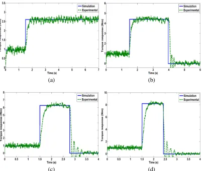
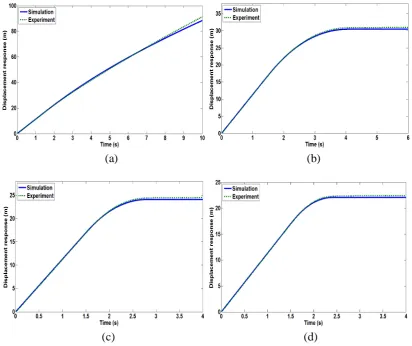
In this model validation, a constant load of 150 N is considered at various current. The
current are varies from 1 A to 4 A with increment of 1 A. The triggering time for the electric
current in modelling is 1.5 s which is same as experimental. Figure 3, Figure 4 and Figure 5
show the model validation result at various current. The simulation model was developed
using MATLAB based on the equations of MR brake with test rig in the previous section and
the parameters given in table 1.
Table 1. MR Brake Parameter
Parameter
Value
Outer radius of disc,
Inner radius of disc,
Number of surfaces, N
MR fluid gap, h
0.04 m
0.01 m
2
0.0025 m
(a) (b)
(c)
(d)
Figure 3. Comparison between model and experimental at several applied current for shaft
angular velocity response; a) 1 A, b) 2 A, c) 3 A and d) 4 A
(a)
(b)
(c)
(d)
Figure 4. Characteristic of torque response between model and experimental; a) 1 A, b) 2 A,
c) 3 A and d) 4 A
(a)
(b)
(c)
(d)
Figure 5. Comparison between model and experimental of load displacement response at
several applied current; a) 1 A, b) 2 A, c) 3 A and d) 4 A
The model and experimental results are compared and it shows a close relationship
between both results. This response indicates that the model of MR brake actuator with a test
rig is valid. However, the response time of MR brake torque to reach constant steady-state has
a delay time which is shown in Figure 4. This is due to the delay response of material and
sensory system. However, the trend of experimental follow the model is similar.
4.
ConclusionAcknowledgments
The authors gratefully acknowledged the financial support from Universiti Teknikal Malaysia Melaka and The Ministry of Higher Education, Malaysia (MoHE) under Exploratory Research Grant Scheme (ERGS), grant no.: ERGS/1/2012/TK08/UTEM/02/1/E00007.
References
[1] Poynor J C and Reinholtz C 2001 Innovative Designs for Magneto-Rheological Dampers
Expedition
[2] Wang X and Gordaninejad F 2003 LYAPUNOV-BASED CONTROL OF A BRIDGE USING MAGNETO-RHEOLOGICAL FLUID DAMPERS Intelligent Material System and Structure, 4331 1-14.
[3] Diep T, Thanh C and Ahn K K 2006 Intelligent phase plane switching control of pneumatic artificial muscle manipulators with magneto-rheological brake October 16(May 2005) 85-95
[4] Gudmundsson K H, Jonsdottir F and Thorsteinsson F 2010 A geometrical optimization of a magneto-rheological rotary brake in a prosthetic knee Smart Materials and Structures IOP 11-19
[5] Karakoc K, Park E J and Suleman A 2008 Design considerations for an automotive magnetorheological brake Mechatronics18 434-447
[6] Kamal M, Rahman M M and Rahman A G A 2013 Inter J Automot Mech Eng 7 912.
[7] Nagarkar M P, Vikhe G J, Borole K R and Nandedkar V M 2011 Inter J Automot Mech Eng 3 364
[8] Kamal M, Rahman M M and Rahman A G A 2012 J Mech Eng Sci 3 291
[9] Carlson J D 2001 What Makes A Good MR Fluid? In Electrorheological (ER) Fluids and Magneto-rheological (MR) Suspensions USA 1-7
[10] Bossis G 2002 Magnetorheological fluids Magnetism and Magnetic Materials252 224-228 [11] Jolly M R, Bender J W and Carlson J 1998 Properties and applications of commercial
magnetorheological fluids In Proc. of SPIE, 5th Annual Intern. Symposium on Smart Materials and Structure Cary NC 262-275
[12] Park E J 2006 A performance evaluation of an automotive magnetorheological brake design with a sliding mode controller Mechatronics 16 405-416
[13] Li W Hl 2007 A 2-DOF MR actuator joystick for virtual reality applications Sensors And Actuators 137 308-320
[14] Park E J, Falcao L and Suleman A, 2008 Multidisciplinary design optimization of an automotive magnetorheological brake design Computers and Structures86 207-216 [15] Karakoc K, 2008 Design of a Magnetorheological Brake System Based on Magnetic Circuit
Optimization Engineering
[16] Tan K P, Stanway R, and Bullough W A 2007 Braking responses of inertia / load by using an electro-rheological ( ER ) brake Mechatronics17 277-289
[17] Nam, T H and Ahn K K 2009 A new structure of a magnetorheological brake with the waveform boundary of a rotary disk Smart Materials and Structures IOP18 1-4
[18] Liu B et al 2006 Development of an MR-brake-based haptic device Smart Materials and Structures15 1960-1966
[19] Philips, 1969. Engineering applications of fluids with a variable yield stress PhD thesis (University of California: Berkeley, CA)