Usage of Magnetorheological Damper in Active Front Bumper System
for Frontal Impact Protection
Alif Zulfakar bin Pokaad
1, a, Khisbullah Hudha
2,band Md Radzai bin Said
2,c1
Faculty Engineering and Technology, Multimedia University, Jalan Ayer Keroh Lama, Bukit Beruang, 75450, Malaysia
2
Faculty of Mechanical, University Technical Malaysia Malacca, Hang Tuah Jaya, Durian Tunggal, 76100, Malaysia
a
[email protected], [email protected], c [email protected]
Keywords: Active front bumper, magnetorheological damper and skyhook controller
Abstract. In this paper, the effectiveness of the active bumper system to reduce the jerk of a vehicle during collision is discussed. The mathematical model is done by using MATLAB 7.0 to simulate a collision between a pendulum and a vehicle installed with the active bumper system. In the active bumper system, it consists of three parts which are magnetorheological(MR) model, inner controller and outer loop controller. The validated model is used to develop an inner loop controller by implementing a close-loop PI control to track the desired damping force through simulation. The governing equations of motions of vehicle collision and MR damper model are then integrated with the well known control strategy namely skyhook control. The performance of skyhook control is then compared with the vehicle with passive damper and common vehicle by using computer simulation in order to reduce the acceleration and the jerk of the vehicle during collision.
Introduction
Currently, the researches on passenger vehicle design technology are continuously developed in order to increase the level of safety and comfort. Intelligent Vehicle Systems are the key to achieve this objective [1]. Active bumper system is a frontal protection system that consists of active mechanism for absorbing the collision energy. The active bumper system is designed to reduce frontal collision impact of the automobile for the purpose of the safety level of the driver and the passenger in vehicle. Active bumper system should work properly in absorbing energy as much as possible during frontal impact. The active bumper system should send the signal to a control mechanism to react or extend only when a dangerous collision is imminent [2]. Magnetorheological fluid is a type of smart fluid that changes its characteristic in term of elasticity, plasticity, and viscosity subjected with magnetic field. The properties of MR fluids have contained a synthetic or silicone based oil, and ferromagnetic particles that have 20–50 µm in diameter. When a magnetic field is applied to the fluid, the ferrous particles will align and form linear chains parallel to the magnetic field [3]. The main advantage of MR fluids over conventional fluids is it ability to achieve a wide range of viscosity in a fraction of millisecond. Thus, MR Fluids can be effectively utilized in vibration control of various dynamic systems including vehicle shock absorber, dampers and engine mounts [4]. Many of researcher had studied the feasibility and applicability of a semi-active magnetorheological (MR) shock isolation system using skyhook control algorithm to replace a conventional passive shock isolation system on the computer simulation [5,6,7]. From the previous research, it can be concluded that the skyhook control has the ability to reject the unwanted motion from the vehicle compared with the passive damper that introduced in the vehicle. So, the objective of this paper is to investigate the effectiveness of active bumper system to reduce the jerk and acceleration of the vehicle during and after the collision.
Vehicle Collision Model
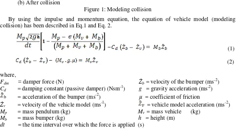
Figure 1 shows the situation of the collision between pendulum and the model of the vehicle. At the initial condition, the vehicle is at static condition. The pendulum will crash the vehicle by moving from point 1 to point 2.
(a)Before collision (b) After collision
Figure 1: Modeling collision
By using the impulse and momentum equation, the equation of vehicle model (modeling collision) has been described in Eq.1 and Eq. 2.
(1)
(2)
where,
Fdm = damper force (N) Żb = velocity of the bumper (ms-2)
Cd = damping constant (passive damper) (Nsm-1) g = gravity acceleration (ms-2) = acceleration of the bumper (ms-2) μ = coefficient of friction
Żv = velocity of the vehicle model (ms-1) = vehicle model acceleration (ms-2) Mp = mass pendulum (kg) Mv = mass vehicle (kg)
Mb = mass bumper (kg) h = height (m)
dt = the time interval over which the force is applied (s)
Modelling of MR Damper
The modeling of Magnetorheological (MR) damper under impact loading is developed by using a polynomial method which has been validated with the experimental results as shown in Fig. 2.
(a) Force vs velocity for 15 kg pendulum mass b) Force vs velocity for 20 kg pendulum mass Figure 2: Characteristics comparison for MR damping force between experimental and modeling
Vehicle model accelerate
The polynomial model is developed based on curve fitting from experimental results and consists of a three regions namely fluid locking, positive and negative acceleration regions. The details on how the value of MR damper damping force from experimental to be implemented into the modelling had been described in our previous research [8]. The general formula of force transmitted by MR damper under impact loading is shown below:
(3)
(4)
Where,
αm and = dimensionless parameter for transmitted force and velocity of the damper
fd and = damping force and velocity of the damper at mass of pendulum 25 kg
I = current input t = time during impact loading
F(t) = transmitted force by MR damper v(t) = velocity of the damper
Controller Structure
The controller structure implemented in this study is shown in Fig. 3 which consists of two loops namely outer and inner loops controller. The function of the inner loop control is to track the actual force that generated by the MR damper to closely follow the desired force produced by the outer loop control.
Figure 3: The controller structure of active bumper system
Inner Loop Controller
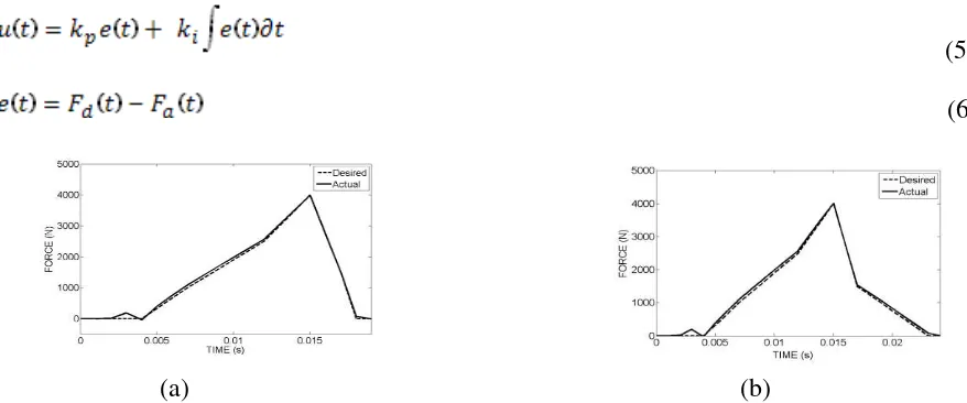
The inner loop control structure of the proposed MR damper model use a simple PI control as shown in Fig. 4. The Proportional and Integrator, (PI) controller is formulated as follows, where Fd is the desired damping force and Fa is the actual damping force.
(5)
(6)
(a) (b)
Outer Loop Controller
The semi active damper has the limitation to provide the damping force if the force sign is in opposite direction with the sign of relative velocity between vehicle and bumper. In order to reduce this effect, semi active skyhook control essentially switches the damper force onto the desired force when force and relative velocity are in phase (same sign) and turns the damper off when they are out of phase (opposite sign) [9]. The logic of the on-off skyhook control as follows,
if (7)
if (8)
Result and Discussion
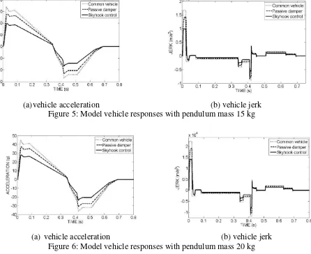
The performance of the semi-active controllers in generating the desired damping force is investigated by applying a differential external force with the variation of pendulum mass in 15 and 20 kg. The implementation of skyhook control is evaluated for it performance at controlling the acceleration and the jerk of the vehicle during and after the collision. Common vehicle means that no damper has been attached at the vehicle and all impact force is transmitted to the vehicle. Fig. 5 and 6 show the simulation results of common vehicle, passive and semi-active damper with skyhook control algorithm at the pendulum mass of 15 and 20 kg.
(a)vehicle acceleration (b) vehicle jerk Figure 5: Model vehicle responses with pendulum mass 15 kg
(a) vehicle acceleration (b) vehicle jerk Figure 6: Model vehicle responses with pendulum mass 20 kg
damper of -13 g to 20 g. Besides, the common vehicle has the highest peak to peak jerking in the range of -9500 ms-3 to 16000 ms-3 followed by the vehicle with passive damper with the range of -8900 ms-3 to 14200 ms-3 and vehicle with skyhook control shows the lowest peak to peak jerk in range of -5100 ms-3 to 9995 ms-3. The semi-active suspension system using skyhook control also offers significant improvement on vehicle acceleration and jerk at the pendulum mass of 20 kg as shown in Fig. 6(a) and 6(b). The peak to peak acceleration for the common vehicle is 45 g to -37 g followed by the vehicle with the passive damper of -32 g to 37 g and vehicle with the skyhook control damper of -24 g to 28 g. The highest peak to peak jerking of the vehicle is shown at the common vehicle where is in the range of -15000 ms-3 to 22500 ms-3 followed by the vehicle with passive damper in the range of -12500 ms-3 to 18500 ms-3 and the vehicle with skyhook control shows the lowest peak to peak jerk in the range of -8500 ms-3 to 14600 ms-3. It can be concluded that the semi active damper has the ability to reduce the acceleration and jerk of the vehicle the jerk of the vehicle which is more than 50% reduction compared to the common vehicle at the pendulum mass of 15 and 20 kg.
Conclusion
In this research, the controllability of the proposed model is investigated in simulation study by realizing a simple closed-loop PI control. From the simulation results, it can be seen clearly that under several input functions, the proposed polynomial model tracks the desired damping force well. In addition, the capability of the skyhook control in rejecting the unwanted has been evaluated by using a computer simulation. From the simulation result, skyhook control algorithm implemented for the semi active damper was significantly minimized the acceleration and the jerk of the vehicle during and after the collision compared to the passive damper and common vehicle.
References
[1] Rekveldt, M.G.C., (2003), ‘Literature Survey on in-Vehicle Safety Devices’, TNO report
03.OR.BV.037.1/MRE.
[2] Bonnel, M., Pointer, S., Bodurtha, E., and Castro, R., (2004), ‘The Active Bumper System’, Department of Mechanical, Industrial and Manufacturing Engineering College of Engineering, Northeastern University.
[3] Ahmadian, M., (1999), ‘On the Isolation Properties of Semiactive Dampers’, Journal of
Vibration and Control, 5(2), pp. 217 – 232.
[4] Hong, S.R., Choi, S.B., Choi, Y.T., and Wereley, N.M., (2005), ‘Non-Dimensional Analysis and
Design of a Magnetorheological Damper’, Journal of Sound and Vibration, 288, pp. 847-863.
[5] Karnopp, D., (1990), ‘Design Principles for Vibration Control of Systems Using Semi-Active
Dampers’, Transactions of the ASME, Vol. 112, pp.448-455, September.
[6] Besinger, F. H., Cebon, D., and Cole, D. J., (1995), ‘Force Control of a Semi-Active Damper’,
Journal of Vehicle System Dynamics, 24, pp 695–723.
[7] Choi, Y.T., and Werely, N., (2008), ‘Shock Isolation Systems Using Magnetorheological
Dampers’, Journal of Vibration and Acoustics, Vol. 130 / 024503-1.
[8] Alif Z., Hudha K., Nasir Z., and Ubaidillah. (2011) Simulation and Experimental Studies on the Behavior of a Magnetorheological Damper under Impact Loading. International Journal of Structural Engineering, Vol. 2 No. 2 pp 164-187.
Usage of Magnetorheological Damper in Active Front Bumper System for Frontal Impact Protection