ii
“I hereby declare that this project report is written by me and is my own effort and that
no part has been plagiarized without citation”
Signature : ………..
Name of Writer : ………..
iii
DEDICATION
iv
ACKNOLEDGEMENT
First, author would like to express my gratitude to the supervisor Puan Siti Hajar Bt Sheikh Md Fadzullah for her encouragement and support. Also thank you for
guidance along this project.
I also would like to thank to Puan Ruzy Haryati Bt Hambali for her support and advise. For En. Fairuz who has given his time to teach me about the machine.
Lastly but not least this appreciation also wish to anyone whose was involved for help this project. I hope that that this report will become source of references to students in future.
v
ABSTRACT
vi
ABSTRAK
vii
LIST OF TABLE
NO. TITLE PAGE
1.0 Gantt Chart for the Research Activity in this Project. 5
2.1 Comparison of Rapid Prototyping 19
2.2 Rule of Thumb Miniature Feature Size 28
2.3 Type of 3D Printer 37
2.4 General Definition of Mechanical Properties 38
2.5 RapidSteel properties 38
2.6 Copper polyamide properties 40
2.7 Properties of bronze-based sintered powder and manufacturing
time and cost 41
2.8 Processing data and properties of Ref. and prepared by 3D-Printing
Al2O3/Cu-alloy composites 47
3.0 Dimension for each specimen 50
3.1 Identification of Chemical Substance and Company 50
3.2 Composition / information of Ingredients 51
3.3 Physical and Chemical Properties 52
3.4 Stability and reactivity 52
3.5 Identification of Chemical Substance and Company 53
3.6 Composition / information of Ingredients 53
viii
3.8 Stability and reactivity 55
3.9 Technical Specification for Zprinter 310 Plus 59
3.10 Dimension for each specimen 60
4.1 Experimental and Theoretical value of Yield Strength for
different type of specimen 64
4.2 Compressive Strength data from Experiment and Theoretical 68
4.3 Modulus of Elasticity data for Experiment and Theoretical 71
5.0 Experimental Result for Three different Type of Specimens 74
ix
LIST OF FIGURE
NO. TITLE PAGE
2.1 Schematic diagram of stereolithography 12
2.2 Schematic diagram of laser sintering 13
2.3 Schematic diagram of FDM 14
2.4 Schematic diagram of 3D printing 14
2.5 Schematic diagram of laminated object manufacturing 15
2.6 Stairstepping 23
2.7 Surface finish for each type of RP 24
2.8 Surface Finish of Sculpture 25
2.9 Three-dimensional printing process 29
2.10 Gas-atomized (left) and water-atomized (right) 316L stainless
steel powder 32
2.11 Ink-jet printed, two-dimensional ZrO2 structure with 170 μm
resolution. The distance between the outer vertical surfaces of
adjacent walls is approximately 1 mm 33
2.12 Three-dimensional structures fabricated by direct ceramic
ink-jet printing. The optical image is shown on the left; the
x
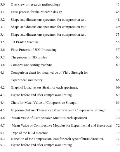
3.0 Overview of research methodology 45
3.1 Flow process for the research design 46
3.2 Shape and dimensions specimen for compression test 48
3.3 Shape and dimensions specimen for compression test 49
3.4 Shape and dimensions specimen for compression test 55
3.5 3D Printer Machine 56
3.6 Flow Process of 3DP Processing 57
3.7 The process of 3D printer 60
3.8 Compression testing machine 60
4.1 Comparison chart for mean value of Yield Strength for
experiment and theory 65
4.2 Graph of Load versus Strain for each specimen. 66
4.3 Figure before and after compression testing 67
4.4 Chart for Mean Value of Compressive Strength 69
4.5 Experimental and Theoretical Mean Value of Compressive Strength 70
4.6 Mean Value of Compesssive Modulus each specimen 72
4.7 Mean Value of Compressive Modulus for Experimental and theoretical. 72
5.1 Type of the build direction. 77
5.2 Direction of the compression load for each type of build direction. 77
[image:11.612.112.523.79.599.2]xi
TABLE OF CONTENT
CHAPTER INDEX PAGE
DECLARATION ii
DEDICATION iii
ACKNOLEDGEMENT iv
ABSTRACT v
ABSTRAK vi
LIST OF TABLE vii
LIST OF FIGURE ix
TABLE OF CONTENT xi
CHAPTER 1 INTRODUCTION
1.1 Rapid Prototyping 2
1.2 Three Dimensional Printer 4
1.3 Aim of Work 4
1.4 Problem Statement 4
1.5 Planning Execution 5
CHAPTER 2 LITERATURE REVIEW
2.1 Rapid Prototyping 6
2.1.1 Type of RP technique 12
xii
2.1.3 Comparison of RP Technique 17
2.2 Three Dimensional Printer 27
2.2.1 Basic Process 29
2.3 Material 30
2.3.1 Powder Based 31
2.3.1.1 Metal Powder 31
2.3.1.2 Ceramic Powder 33
2.4 Mechanical Properties 36
2.4.1 Mechanical Properties of Part Produce 37 from Metal Powder
2.4.2 Mechanical Properties of Part Produce 42 from Polymer Powder
2.4.3 Mechanical Properties of Part Produce 43 from Ceramic Powder
CHAPTER 3 METHODOLOGY
3.1 Research Design 44
3.2 Design of Test Specimen 46
3.2.1 Design of experiment 47
3.2.2 Design of Test Specimen Via 47
SolidWorks
3.3 Raw Material 49
3.4 3D Pinter 54
3.4.1 Processing 56
3.5 Mechanical Testing 58
3.5.1 Compression Test as per ASTM D695 58
3.5.1.1 Equipment/ Testing Apparatus 59
xiii
CHAPTER 4 RESULT AND ANALYSIS
4.1 Stress-strain Relationship of Part Produce from 63 3-D Printer under Compression Force
4.2 Compressive Strength of Part Produce from 68
3-D Printer
4.3 Compressive Modulus of Part Produce from 70
3-D Printer
CHAPTER 5 DISCUSSION 73
CHAPTER 6 CONCLUSION 80
CHAPTER 7 SUGGESSTION AND RECOMMENDATION 81
FOR FUTURE WORKS
REFFERENCES 82
BIBLIOGRAFI 85
1
CHAPTER I
INTRODUCTION
Rapid Prototyping (RP) is a technology that provides the ability to build or fabricate prototypes for initial design of a product. There are various materials can be used in producing the prototypes needed, which depends on the RP machine itself. For 3D-Printer Machine, it actually can be simplified as a commercial RP process. Various process parameters can be found in 3D-printer which affects the character of RP parts; including build direction, layer thickness, temperature and so on. Layer thickness actually refers to the thickness of each part being produced by the 3D-Printer Machine.
Before any products become a product that can be use in human life, one sample or prototype required as a specimen. This is because the sample will used to allow for demonstration, evaluation or testing for the proposed product. The technology that used to make the prototype is define as Rapid Prototyping (RP) and usually come first before a specific mold tool and jigs are design. For make prototyping traditionally required skill of employee, time and cost. These three causes usually applied for cutting, bending, shaping and assembly the part that needed.
2
by adding successive layers of material. Usually mold, jigs and die are also include the quickly fabrication of the tools required for mass production. Now, there are many different manufacturing process have develop using an increasing the range of material [1,].
1.1 Rapid Prototyping
Rapid Prototyping (RP) is referred to as a class of technology can automatically build a physical model from Computer-Aided Design (CAD) data. This technology make designer quickly create prototypes of their design, although just two dimension pictures [1, 2, 3, 5, 7, 9,10]. Prototype can also be used in design testing. Other than that, RP also can be use to make tooling and any production part. RP is usually best manufacturing process for small production runs and complicated object. Most producing prototype take shortly time, but the time that required depends on the size and the complexity of the object. This process rather consumes more time make the prototype but still better than conventional method such as machining. Rapid prototyping system is a technology that emerges in 1980s. During the modern concept of Rapid prototyping was conceived and developed; actually the origin of this technology is back to the 1890s [1]. This is some of the most popular and commonly used RP technique [3,10]:
i. Selective laser sintering (SLS)
ii. Fused Deposition Modeling (FDM)
iii. Stereolithography (SLA)
iv. Multi Jet Modeling (MJM)
v. Laminated Object Manufacturing (LOM)
vi. Electron Beam Melting (EBM)
vii. 3D Printing (3DP)
3
1.2 Three -dimensional Printer
Three-Dimensioning printing refers to a category of rapid technology which is converting a virtual 3D model to become a physical object. Typically, 3D printer is an extremely flexible system, capable of creating part of any shape using any material including ceramics, metals, polymers and composites. 3D printer also generally faster and easier to use than other additive technologies. Three-dimensional printing (3DP) developed by the Massachusetts Institute of Technology and licensed to Z Corporation of Burlington, Massachusetts. The material usually use in this system is limited to two choices: plaster or starch.
Usually the material that is recommended is the plaster based because it is more durable and gives better resolution. Starch should be used if need making investment mold. After finish printing the part, it should be infiltrated. Infiltrants that are used to wax includes cyanoacrylate (superglue) and Z Max epoxy [4].
A unique capability of three-dimensional printing is the ability to produce multicolored parts. A part’s color is determined by dyes added to the liquid binder. Almost any color is possible. Each layer, in essence, is like a full-color image printed on a flat sheet of paper by an ink-jet printer
4
1.3 Aim of Works
The objective in this project is:
To design and fabricate part from powder- based material using 3D printer.
To investigate the mechanical properties of part produced.
The scope in this project is:
To design a part from powder- based material used in rapid prototyping.
To fabricate part using 3d printer machine.
To investigate the mechanical properties of part including compression test as per ASTM D695.
1.4 Problem Statement
This research is dedicated to the study of particularly for compression behavior of part which produces using 3D-Printer Machine. From the literature review, many researches reported about the specimen dimension, technical specification of machine but very few resources have reported about mechanical properties of powder-based part produced from the 3D Printer.
1.5 Planning and Execution
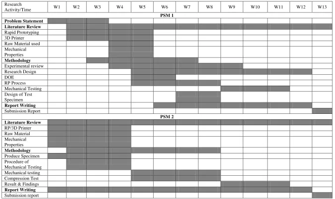
Table 1 below depicts the research activity that is carried out throughout the project. The first four months is dedicated to the literature review and design of the
5
Table 1.0: Gantt Chart for the Research Activity in this Project.
Research
Activity/Time W1 W2 W3 W4 W5 W6 W7 W8 W9 W10 W11 W12 W13
PSM 1 Problem Statement
Literature Review
Rapid Prototyping 3D Printer Raw Material used Mechanical Properties Methodology Experimental review Research Design DOE RP Process Mechanical Testing Design of Test Specimen Report Writing Submission Report PSM 2 Literature Review RP/3D Printer Raw Material Mechanical Properties Methodology Produce Specimen Procedure of Mechanical Testing Mechanical testing Compression Test Result & Findings
Report Writing
6
CHAPTER II
LITERATURE REVIEW
2.1 Rapid Prototyping
Rapid Prototyping (RP) refers to a group of technologies that can fabricate physical, three dimensional part of arbitrary shape directly from Computer Aided Design (CAD) and Computer Aided Manufacturing (CAM) by fully automated, fast and highly flexible process [2, 5, 7, 8, 9, 10]. According to the Wohler Report (2004), Rapid Prototyping refers to fabricate a physical model of a design using digital driven, additive processes. RP also produce model very quickly from 3D CAD data, CT and MRI scans, and data from 3D digitizing system. This means, Rapid Prototyping method can save the processing time and also save cost producing the prototype than using conventional technique for fabricating physical model which can be more expensive and also time consuming which may take a few days or even weeks [2, 5].
Rapid Prototyping was emerged in 1980’s, where the high technology was conceived, developed and promote in 1980’s. 1890’s is the date of the origin technology. For the early history for rapid prototyping, it’s also known a layered manufacturing.
7
to produce tool or even prototype and usually the product that have produce in small quantities [2].
This technology allow designer quickly create prototypes of their design, although just two dimension pictures. Designer will makes the prefect visual aids for show their ideas to their co-workers and also to customers. Prototype usually numerous use such as, it can be use in design testing. Other than that, RP also can be use to make tooling and any production part. RP is usually best manufacturing process for small production runs and complicated object. Most producing prototype take shortly time, but the time that required depends on the size and the complexity of the object.
RP system has it own advantages such as; prototype that required can build even though the prototype has a complex shape. It also builds the prototype without setting the arrangement of the machine. Besides that, RP also build the prototype using multiple materials by available technique. Other than that, RP has reduced time to market. Cut trial cost and improved the quality of the product.
RP have become an important part of the product development process. By using RP has time taken can be reduced, cut cost and improve the quality of the product. This means, RP allowed user do and fabricate the design and prototype to verify before they involve in the expensive tooling and fabrication of mass production. Below are several type of application in education and industry [2].
i. Application in Product Development
8
design for making improvement of the product. The most application can be dividing into three major categories:
a) Prototype Design Evaluation b) Prototype for Function Verification
c) Prototype for Manufacturing Process Validation
ii. Application in Reverse Engineering
Reverse Engineering is science by taking the physical model and produce it surface geometry in 3D data file on CAD file. RE is the faster way to get 3D data into any computer system. The example for this application is situation includes hand made prototypes, craft work, dental application and reproduction of old engineering object.
iii. Application in Casting and Pattern Making
This application is important for casting and pattern making. Casting allows fabricate complex shape but for the simple shape machining can be used.
iv. Application in Rapid Tooling
According to the rapid solution web, Rapid tooling is using a rapid prototype, either indirectly or directly, as a tooling pattern for creating a mold. Rapid tooling techniques enable you to have molds with the correct material at a substantially reduced cost in a fraction of the time it takes to produce parts from production tooling processes. The greater the complexity of the part, is the greater the benefits of cost and time.
v. Application in Medical
9
different, and the size of the parts makes it possible to fabricate the products in large, economical batches with existing equipment.
vi. Application in Rapid Manufacturing
a. In Rapid manufacturing, there are still having a lot of challenges for the limitation of speed, material and accuracy. But by using the rapid
prototyping technology most of the companies show the
successfully[2,3,7,9]
According to Rochus, et.al (2007) their article was reported rapid prototyping and manufacturing are known to be destructive technologies. Everyday industry used of this method has increase rapidly. The principal of this technology of manufacturing parts is layer by layer starting from liquid, paste or powder. After the material is deposited, the selecting surface is treated according to a process define by the chosen technique in order to solidify a cross section of the final component. This process are applied for prototyping, small series, injection moulds manufacturing, mock-ups and also used in several engineering sectors. In their article also state the general description for the rapid prototyping technique such as, Stereolithography (SLA), Selective Laser Sintering (SLS) and Jet Based Technology. The start with a 3D CAD model, then the model need to convert to the stereolithography (STL) format. Only this format can be read by the machine. This is because the format will change dividing the model into layer form. By dividing the object into the layer form, the machine will printed the object layer by layer according to the STL format. This process is continuously until the layer becomes an object.
10
as Stereolithography (SLA) and the laminated sheet based process included the Laminated Object Manufacturing (LOM) process. Generally all the principal of process are similar but the things that make the technique different are the materials that use to make prototyping. In this paper also mention the advantage of this technology such a reducing time and cost. This is because, all the process will make the prototype in the short time than the traditionally method. And also can produce more prototypes in one time. Besides that, this technology make the cost reduce by making the prototype in exactly as the real one. But, this technology has the limitation such as the quality and accuracy. But not all the system of RP has this problem [Choi,et al (2003)].
According to Durham. (2003) Rapid Prototyping is very useful in industry. This is because RP is a powerful tool to reducing time to market and it also improving quality and reducing cost. He also said the challenge is during selecting the suitable process that need to use. During making decision for what process that need to choose, the important thing that needs to consider is combination with the intended material. This is because; selecting a process without considering the material will yield the questionable result. In his article also state the RP process that usually used in industry which is, Stereolithography (SLA), Selective Laser Sintering (SLS) and also PolyJet. In this article also mention comparison the process as the material available for each. Stereolithography (SLA) process is used material in liquid resin. The process is using ultraviolet laser to solidify the material. Although the SLA is limited in its range of applicable material, it is suitable for conceptual visualization. Selective Laser Sintering (SLS), the material is from powder material. The SLS process create the object by heating the powder using heat from a carbon dioxide laser fuses (sinter). The advantage for this process is more widely using in industry and also suitable for function analysis.