A RAIL CENTRAL DISPLACEMENT METHOD ABOUT GB-SAR
J. Peng a, *, J. Cai a, H. Yang a
a China University of Geosciences (Beijing), 100083 Beijing, China - [email protected]
Commission VII, ThS 7
KEY WORDS: Ground Based Synthetic Aperture Radar (GB-SAR), Rail Displacement Error, Landslide Monitoring, Dis-continuous GB-SAR, Artificial Corner Reflectors, Atmospheric Phase
ABSTRACT:
This paper presents a new method to correct rail errors of Ground Based Synthetic Aperture Radar (GB-SAR) in the discontinue mode. Generally, “light positioning” is performed to mark the GB-SAR position in the dis-continuous observation mode. Usually we assume there is no difference between the marked position and the real installation position. But in fact, it is hard to keep the GB-SAR positions of two campaigns the same, so repositioning errors can’t be neglected. In order to solve this problem, we propose an algorithm to correct the rail error after analyzing the GB-SAR rail error geometry. Results of the simulation experiment and the real experiment of a landslide in Lvliang, Shanxi, China, show the proposed method achieves an mm-level precision, enabling the D-GBSAR mode to be used in engineering projects.
* Corresponding author
1. INTRODUCTION
Ground Based Synthetic Aperture Radar (GB-SAR) is a radar-based terrestrial remote sensing imaging system (Tarchi et al., 1999), consisting of a precision rail track and a radar sensor emitting and receiving microwaves repeat-pass along the rail (Noferini, 2004). It obtains the target deformation by interfering the observation data. Ku band GB-SAR is often used in deformation monitoring, as its short waves can achieve high precision. The precision of GB-SAR measurements varies from sub-millimeters to a few millimeters according to the target characteristics and the distance between sensor and target (DST). For some artificial targets, precision better than 1mm is attainable (Takahashi et al., 2013). With the flexibility, GB-SAR can acquire deformations from as large as several meters per hour to as small as few millimeters per year (Leva et al., 2003) by adjusting the observation model and period. So it can be applied in open pit slope stability monitoring (Casagli et al., Farina et al., 2011; Farina et al., 2012; Mecatti et Al., 2010; and Severin et al., 2011), landslides monitoring (Tarchi et al., 2003b; Luzi et al., 2006; Herrera et al., 2009; Corsini et al., 2013; Barla et al., 2010; Schulz et al., 2012), urban monitoring (Pieraccini et al., 2004; Tapete et al., 2013; Pipia et al., 2013), structure monitoring (Tarchi et al., 1997), dam monitoring (Tarchi et al.,1999; Alba et al., 2008; Luzi et al., 2010a), and glacier monitoring (Luzi et al., 2007, Noferini et al., 2009; Hyangsun and Hoonyol, 2011).
GB-SAR data can be acquired using two types modes: the continuous (C-GBSAR) and the dis-continuous (D-GBSAR). For the C-GBSAR mode, instruments are installed in situ, acquiring data on a regular base (e.g., every a few minutes). For the D-GBSAR mode, instruments are installed in each campaign and revisited a given site periodically (e.g., weekly, monthly or yearly) depending on the deformation speed (Noferini et al., 2008; Luzi et al., 2010b). D-GBSAR is especially useful in monitoring slow deformations.
Traditional GB-SAR algorithm assumes that interferometric images are constituted by deformation phase, topographic phase, atmospheric phase and noise. However, in the D-GBSAR mode, it is hard to ensure the GB-SAR positions to exactly the same in two campaigns, so this repositioning error called GB-SAR rail error in this paper should be considered. In this case, “light positioning” is usually used to reduce the GB-SAR rail error, i.e., by simply materializing the GB-SAR location using some marks. Then co-registrations should be implemented. Detailed information of the algorithms can be found in Lin et al. (1992) and Hanssen (2011). However, as the GB-SAR precision can reach the submillimeter level, the co-registration error and residual error of rail still have impact on the measurement results even after marking and co-registration. In order to acquire reliable deformation results, we need correct the GB-SAR rail error.
To estimate and eventually reduce the GB-SAR rail error, a novel technique is proposed discussed in this paper. The first part of this paper introduces fundamentals and principles of GB-SAR, and then a new error model is proposed. Orbit deformation is simulated by computer, and the effect of each component to the monitoring result is analyzed. The last part presents a successful application example of D-GBSAR in monitoring the deformation of a landslide in Lvliang, Shanxi, China, using artificial corner reflectors.
2. MATERIALS AND METHODS
2.1 GB-SAR Error source analysis
atmospheric phase is related to atmospheric parameters which could be corrected by many different approaches (Noferini et al., 2008; Iglesias et al., 2013; Iannini and Guarnieri, 2011); noise
where
= differential interferogram phase R = DST atm
= differential atmospheric phase noise
= differential noise phase
Atmospheric phase is compensated by the method proposed in (Tarchi et al. 1999) which is adapted to the ground-based geometry.Delaying phase due to the weather conditions along a path of length R is : T = temperature in kelvin
e = partial pressure of the water vapor in millibars
As the GB-SAR rail positions in two campaigns can’t be identical, the GB-SAR rail error, called baseline in spaceborne SAR, is introduced. GB-SAR rail errors cause low coherence and instable displacement between two images, which can’t be corrected by spaceborne SAR methods directly due to different geometry between spaceborne SAR and GB-SAR. Based on this, we analyses the geometric relationship between radar sensors and targets, and propose a correction algorithm. The GB-SAR rail error is decomposed to three components in the range, azimuth and vertical direction, respectively. Figure 1(a, c, d) show the geometrical relationship of the three directions. Obviously, the range and azimuth components are related to the azimuth angle and the DST. The error of vertical component
= azimuth direction error phase
, r r
= range direction error phase
, r v
= vertical direction error phase
1 azimuth, the range and the vertical direction
= azimuth angleh = elevation between radar and target
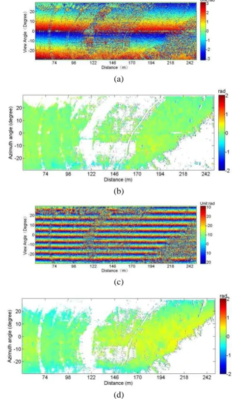
Figure 1. Geometrical relationship of the three directions and simulated results. (a), (b) Azimuth direction. (c), (d) Range
direction. (e), (f) Vertical direction.
As Figure 1(b, d, f) show the influence of range, azimuth and vertical direction rail error on the displacement. Among them, the error of the azimuth is related to rail displacement and azimuth angle, see Fig.1b. With an azimuth angle of 20°, the displacement is 2.92mm, and the GB-SAR rail error will be 1mm. Figure 1(d) shows the error of the range is also correlated to rail displacement and azimuth angle. When the angle of azimuth is 20°and the range displacement is 1.06mm, the rail error will up to 1mm. Figure 1(c) shows correlation between the rail error in the vertical direction with the displacement, range and elevation of the target. If the range between target and radar sensor is 200m, elevation is 50m, and the displacement of unreliable if the GB-SAR rail error is not corrected.
In practice, errors of the three directions (the range direction, azimuth direction and vertical) should be compensated together. A compound function is expressed as:
1 2 T = temperature in kelvin
e = partial pressure of the water vapor in millibars
So the interferogram can be written as:
2 1 2 1 equation can be solved in a least square sense.
2.2 Simulate rail error and atmospheric phase compensation respectively
To verify the error correction model, a simulated experiment with only GB-SAR rail error is designed. GB-SAR instruments are installed in proper sites. Then we move the GB-SAR rail few minutes later to simulate the GB-SAR rail error. At the same time, real displacement of GB-SAR rail is recorded. In order to detect the GB-SAR rail error, we need eliminate the deformation phase, atmospheric phase and noise. Deformation phase is assumed to be zero in this experiment. The atmospheric phase is compensated by the empirical algorithm. And the noise is reduced by filtering. Then only the GB-SAR rail error left. Figure 2 and 3 show the original interferogram and the one after compensated.
Specifically, we firstly move the GB-SAR system 10 mm and then 70 mm along the azimuth direction .Their interferogram is showed in Figure 2 (a) and (c). Obviously, the interferometric
fringes are parallel to the azimuth direction, and they increase with the increase of displacements. These interferogram fringes are caused by the displacement of GB-SAR rail. Because other influential components values are relatively small, the effect of rail displacement is obvious. As the compensated results show, see Figure 2 (b) and (d), the computing rail errors are 8mm and 73mm which have differences of 2mm and 3mm with the real
Figure 2. Rail error in the azimuth direction. (a) Interferogram containing 10mm rail error in the azimuth direction. (b)10mm rail error competition result. (c) Interferogram containing 70mm
rail error in the azimuth direction. (d)70mm rail error compensation result.
(a)
(b)
(c)
(d)
Figure 3. Rail error in the range detection. (a) Interferogram containing 20mm rail error in the range direction. (b) 20mm rail error competition result. (c) Interferogram containing 85mm rail error in the range direction. (d) 70mm rail error compensate
result.
The simulation experiment demonstrates that the proposed method is reasonable and flexible to correct the GB-SAR rail error, providing an mm-level correction precision. The precision in the azimuth direction is better than that in the range direction, because the latter shares similar spatial distribution characteristics with the atmospheric phase (both of them are related to DST), making difficult to distinguish them from each other. Also, the big the distance is, the more difficult the compensation of rail errors in both directions will be.
3. APPLICATION
We applied the proposed method to estimate the deformation of a landslide occurred in Lingjiaping railway station located in Lvliang County, Shanxi, China. The exact position of the landside is at the right side of the MDⅡK53+370~+680 line in
the station. In the middle of November, 2013, a cutting evacuation project was started around the MDⅡK53+50~+630
line. On December 14, 2013, two ring-like cracks appeared on the right side of the through cut, then a landslide happened on December 18. The landslide region is located on the west bank
of the Qiushui River, in the middle of the slope between the Qiushui River and loess hill. The gradient of bedrock surface ranges between 0~24°. The excavation area centered on the terrace and the leading edge. The through cut slope has crossed the earth-rock interface. Figure 4 is a picture of the experiment area. The slop has been reinforced in 2015, but is not stable, so it is suitable to be an experiment area. Twelve corner reflectors installed on the landslide with concrete can be used as stable points to estimate the GB-SAR error phase.
The GB-SAR system used in the experiment is developed by China University of Geosciences (Beijing) and the Beijing Institute of Technology. Figure 5 shows the SDMR-1 GB-SAR system, which consists of a continuous-wave step-frequency transceiver unit working at Ku-band. The band width of the system is 500MHz, and the sample interval is 2min. The range resolution and the azimuth resolution is 0.3m and 4.5@1Km, respectively. Detailed information of the system is showed in Table 1.
Figure 4. Experiment area
Figure 5. GB-SAR system used in the experiment
Name Value
Central Frequency 16.02GHz 2.4m 0.3m 500MHz 30m-3000m 4.5m@1Km Linear Scanning Length
Range Resolution Bandwidth
Illuminating Distance Azimuth Resolution
Table 1. Information of the SDMR-1 GB-SAR system
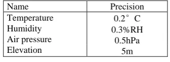
Name Precision
Temperature 0.2°C
0.3%RH 0.5hPa
5m Humidity
Air pressure Elevation
Table 2. Parameters of Portable Meteorograph
Atmospheric phase is related to the DST, so it could be expressed as:
2
0 1 2
4
( )
atm a a R a R
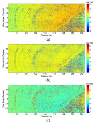
(8)Meteorological parameters (e.g., temperature, humidity, and air pressure), elevation, latitude and longitude are obtained by the TYD-SCW1 Portable Meteorograph. Precision of this instrument is listed in Table 2. Figure 6 (c) and (d) show the correction results of atmospheric phase by Quadratic model and Empirical model, respectively. These similar results show that the two algorithms are both effective to correct the atmospheric phase.
(a)
(b)
(c)
Figure 6. Comparison of empirical models. (a) Original interferogram. (b) Quadratic model compensation result. (c)
Empirical model compensation result.
Twelve corner reflectors were installed on the slide slop, and the GB-SAR was put facing the landslide, so all corner reflectors could be detected in one scan. Two D-GBSAR observation campaigns were performed (10/07/2015, 30/05/2015) with an interval of 41 days. “Light positioning” was used in the first campaign, so the marks can guide the instrument installation in the second campaign. But it is impossible to ensure exactly same installation positions in two campaigns, so correcting the GB-SAR rail error after interfering the two campaign images is necessary. Chose one image from each campaign for interfering, and the interferogram is showed in Figure 7(a). Clearly, both the GB-SAR rail error and atmospheric phase are related to the DST. Then the GB-SAR rail error can be estimated by the proposed algorithm. Displacement in the range direction and azimuth direction are 5.0mm and 2.9mm, respectively. Figure 7 (b) shows the sum of rail determination error and atmospheric phase. Final result of the deformation phase is shown in Figure 7(c), where deformation area is marked in yellow, with a sub-mm-level precision.
(a)
(b)
(c)
Figure 7. Experiment data. (a) Original Interferogram phase. (b) Corrected phase. (c) Deformation.
4. CONCLUSIONS
This paper presents a new method to correct GBSAR rail errors in a discontinue mode. Compared with C-GBSAR, D-GBSAR is preferred for its lower monitoring cost, as the same instrument can be used in different monitoring several sites. But it also introduces new errors called GBSAR rail error, which
be applied to urban monitoring, structure monitoring and open pit mine monitoring.
ACKNOWLEDGMENTS
This work was supported by the following research projects: the National Natural Science Foundation of China (41304012, 61427802, 41330634, 41374016); the Fundamental Research Funds for the Central Universities (2652015180). Hunan Province Key Laboratory of Coal Resources Clean-utilization and Mine Environment Protection (E21422). The authors would like to thank anonymous reviewers who gave valuable suggestion that has helped to improve the quality of the manuscript.
REFERENCES
Alba, M., Bernardini, G., Giussani, A., Ricci, P.P., Roncoronia, F., Scaioni, M., Valgoic, P., Zhangd, K., 2008. Measurement of dam deformations by terrestrial interferometric techniques. Int. Arch. Photogramm., Remote Sens. Spatial Inf. Sci. 37 (part b1), 133–139.
Barla, G., Antolini, F., Barla, M., Mensi, E., Piovano, G., 2010. Monitoring of the Beauregard landslide (Aosta Valley, Italy) using advanced and conventional techniques. Eng. Geol. 116 (3), 218–235.
Casagli, N., Catani, F., Del Ventisette, C., Luzi, G., 2010. Monitoring, prediction, and early warning using ground-based radar interferometry. Landslides 7 (3), 291–301.
Corsini, A., Berti, M., Monni, A., Pizziolo, M., Bonacini, F., Cervi, F., Truffelli, G., 2013. Rapid assessment of landslide activity in Emilia Romagna using GB-InSAR short surveys. In: Landslide Science and Practice. Springer, Berlin, pp. 391–399.
Farina, P., Leoni, L., Babboni, F., Coppi, F., Mayer, L., Ricci, P., 2011. IBIS-M, an innovative radar for monitoring slopes in open-pit mines. In: Proc., Slope Stability 2011: International Symposium on Rock Slope Stability in Open Pit Mining and Civil Engineering, Vancouver (Canada), 18–21September.
Farina, P., Leoni, L., Babboni, F., Coppi, F., Mayer, L., Coli, N., Thompson, C., 2012. Monitoring engineered and natural slopes by ground-based radar: methodology, data processing and case studies review. In: Proc. SHIRMS 2012: Southern Hemisphere International Rock Mechanics Symposium, Sun City (South Africa), 15–17 May.
Ferretti, A., Prati, C., Rocca, F., (2001), Permanent scatterers in SAR interferometry. IEEE Trans. Geosci. Remote Sens. 39 (1), 8–20.
Fortuny-Guasch, J. (2009), A fast and accurate far-field pseudopolar format radar imaging algorithm. IEEE Trans. Geosci. Remote Sens. 47 (4), 1187–1196.
Hanssen, R., 2001. Radar interferometry. Ed. Kluwer Academic Publishers, Dordrecht (The Netherlands). Cong(2015), High-precision Deformation Monitoring Algorithm for GB-SAR System: Rail Determination Phase Error Compensation. SCIENCE CHINA Information Sciences, doi: 10.1007/s11432-015-5446-z.
Hyangsun, H., Hoonyol, L., (2011), Motion of Campbell glacier, east Antarctica observed by satellite and ground-based interferometric synthetic aperture radar. IEEE. In Proceedings of the 3rd Internation Asia-Pacific Conference on Synthetic Aperture Radr.
Iannini, L., Guarnieri, A.M., 2011. Atmospheric phase screen in ground-based radar: statistics and compensation. IEEE Geosci. Remote Sens. Lett. 8 (3), 537–541.
Iglesias, R., Fabregas, X., Aguasca, A., Mallorqui, J.J., Lopez-Martinez, C., Gili, J.A., Corominas, J., 2013. Atmospheric phase screen compensation in ground-based SAR with a multiple-regression model over mountainous regions. IEEE Trans. Geosci. Remote Sens. 99, 1–14.
Leva, D., Nico, G., Tarchi, D., Fortuny, J., Sieber, A.J., 2003, Temporal analysis of a landslide by means of a ground-based SAR interferometer. IEEE Trans. Geosci. Remote Sens. 41, 745
–752.
Lin, Q., Vesecky, J.F., Zebker, H.A., 1992. New approaches in interferometric SAR data processing. IEEE Trans. Geosci. Remote Sens. 30, 560–567.
Luzi, G., Pieraccini, M., Mecatti, D., Noferini, L., Macaluso, G., Galgaro, A., Atzeni, C., 2006. Advances in ground based microwave interferometry for landslide survey: a case study. Int. J. Remote Sens. 27 (12), 2331–2350.
Luzi, G., Pieraccini, M., Mecatti, D., Noferini, L., Macaluso, G., Tamburini, A., Atzeni, C., 2007. Monitoring of an alpine glacier by means of ground-based SAR interferometry. IEEE Geosci. Remote Sens. Lett. 4 (3), 495–499.
Luzi, G., Crosetto, M., Monserrat, O., 2010a. Advanced Techniques for Dam Monitoring. In: Proc. II International Congress on Dam Maintenance and Rehabilitation, Zaragoza, Spain, 23–25 November.
Luzi, G., Monserrat, O., Crosetto, M., Copons, R., Altimir, J., 2010b. Ground-based SAR interferometry applied to landslide monitoring in mountainous areas. In: Proc. Mountain Risks Conference, Florence, Italy, 24–26 November.
Massonnet, D., Rossi, M., Carmona, C., et al. (1993), The displacement _eld of the landers earthquake mapped by radar interferometry. Nature. 364: 138-142.
Massonnet, D., Arnaud, A., (1995), Deation of Mount Etna monitored by space radar interferometry. Nature. 375:567-570.
Mecatti, D., Macaluso, G., Barucci, A., Noferini, L., Pieraccini, M., Atzeni, C., 2010. Monitoring open-pit quarries by interferometric radar for safety purposes. In: Proc. European Radar Conference (EuRAD), Paris, France, 30 September–1 October, pp. 37–40.
measurement. ISPRS Journal of Photogrammetry and Remote Sensing. 93, 40-48.
Nicola Casagli, Filippo Catani, Chiara Del Ventisette, Luzi Guido (2010), Monitoring, prediction, and early warning using ground-based radar interferometry, Landslides, 7 (3), 291–301.
Nico, G., Leva, D., Fortuny-Guasch, J., Antonello, G., Tarchi, D. (2005). Generation of digital terrain models with a ground-based SAR system. IEEE Trans. Geosci. Remote Sens. 43 (1), 45–49.
Noferini, L., 2004. Processing techniques of microwave data acquired by continuous wave stepped frequency radar. PhD thesis, Università degli Studi di Firenze.
Noferini, L., Takayama, T., Mecatti, D., Macaluso, G., Luzi, G., Atzeni, C., 2008. Analysis of Ground-Based SAR data with diverse temporal baselines. IEEE TGRS 46 (6), 1614–1623.
Noferini, L., Mecatti, D., Macaluso, G., Pieraccini, M., Atzeni, C., 2009. Monitoring of belvedere glacier using a wide angle GB-SAR interferometer. J. Appl. Geophys. 68 (2), 289–293.
Pieraccini, M., Luzi, G., Mecatti, D., Fratini, M., Noferini, L., Carissimi, L., Franchioni, G., Atzeni, C., 2004. Remote sensing of building structural displacements using a microwave interferometer with imaging capability. Non Destruct. Test. Eval. 37(7), 545–550.
Pipia, L., Fabregas, X., Aguasca, A., Lopez-Martinez, C., 2013. Polarimetric temporal analysis of urban environments with a ground-based SAR. IEEE Trans. Geosci. Remote Sens. 51 (4), 2343–2360.
Schulz, W.H., Coe, J.A., Shurtleff, B.L., Panosky, J., Farina, P., Ricci, P.P., Barsacchi, G., 2012. Kinematics of the Slumgullion landslide revealed by ground-based InSAR surveys. In: Proc. Landslides and Engineered Slopes: Protecting Society through Improved Understanding – the 11th International and 2nd North American Symposium on Landslides and Engineered Slopes, Banff (Canada), 3–8 June, pp. 1273–1279.
Severin, J., Eberhardt, E., Leoni, L., Fortin, S., 2011. Use of ground-based synthetic aperture radar to investigate complex 3-D pit slope kinematics. In: Proc. Slope Stability 2011: International Symposium on Rock Slope Stability in Open Pit Mining and Civil Engineering, Vancouver, Canada, 18–21 September.
Takahashi, K., Matsumoto, M., Sato, M. 2013. Continuous observation of natural-disaster-affected areas using ground-based SAR interferometry. IEEE J. Sel. Top. Appl. Earth Observations Remote Sens. 6 (3), 1286–1294.
Tapete, D., Casagli, N., Luzi, G., Fanti, R., Gigli, G., Leva, D., 2013. Integrating radar and laser-based remote sensing techniques for monitoring structural deformation of archaeological monuments. J. Archaeol. Sci. 40 (1), 176–189.
Tarchi, D., Ohlmer, E., Sieber, A.J., 1997. Monitoring of structural changes by radar interferometry. J. Res. Nondestruct. Eval. 9(4), 213-225.
Tarchi, D., Rudolf, H., Luzi, G., Chiarantini, L., Coppo, P., Sieber, A.J. (1999). SAR interferometry for structural changes
detection: a demonstration test on a dam. In: Proc. IGARSS 1999, Hamburg, Germany, pp. 1522–1524.