www.elsevier.nlrlocaterjappgeo
Road evaluation with ground penetrating radar
Timo Saarenketo
a,), Tom Scullion
b,1a
Roadscanners Oy, P.O.Box 2219, FIN-96201 RoÕaniemi, Finland
b
Texas Transportation Institute, Texas A & M UniÕersity System, College Station, TX, 77843-3135, USA
Received 9 March 1999; received in revised form 8 June 1999; accepted 10 June 1999
Abstract
Ž .
This paper provides a status report of the Ground Penetrating Radar GPR highway applications based on studies conducted in both Scandinavia and the USA. After several years of research local transportation agencies are now beginning to implement GPR technology for both network and project level surveys. This paper summarizes the principles of operation of both ground-coupled and air-launched GPR systems together with a discussion of both signal processing and data interpretation techniques. In the area of subgrade soil evaluation GPR techniques have been used to nondestructively identify soil type, to estimate the thickness of overburden and to evaluate the compressibility and frost susceptibility of subgrade soil. In road structure surveys, GPR has been used to measure layer thickness, to detect subsurface defects and to evaluate base course quality. In quality control surveys, GPR techniques have been used for thickness measurements, to estimate air void content of asphalt surfaces and to detect mix segregation. Future developments are described where the technique has great potential in assisting pavement engineers with their new pavement designs and in determining the optimal repair strategies for deteriorated roadways.q2000 Elsevier Science B.V. All rights reserved.
Keywords: Ground penetrating radar; Road structure; Subgrade; Dielectric value
1. Introduction
In Scandinavia, the first Ground Penetrating
Ž .
Radar GPR tests with ground-coupled anten-nae were performed in early 1980s in Denmark
ŽBerg, 1984 and in Sweden Johansson, 1987 ,. Ž .
but the method did not gain general acceptance at that time. In Finland the first tests were made
Ž .
in 1986 Saarenketo, 1992 and after the Road District of Lapland of the Finnish National Road
Ž .
Administration Finnra purchased its own unit
)Corresponding author. E-mail:
1
E-mail: [email protected].
in 1988, the method has been used as routine survey tool in various road design and
rehabili-Ž
tation projects in Finland Saarenketo, 1992; Saarenketo and Maijala, 1994; Saarenketo and
.
Scullion, 1994 . Most of the research and devel-opment works in highway applications in Fin-land has been performed with low frequency
Ž100–500 MHz ground-coupled antenna in or-.
der to evaluate subgrade soils and their interlay-ers, probe the depth of overburden and survey road structural layers. GPR technique was also
Ž
applied in aggregate prospecting Saarenketo
.
and Maijala, 1994 . In early- and mid-1990s tests with high frequency 1.0–1.5 GHz air-cou-pled and ground-couair-cou-pled antennae were started
0926-9851r00r$ - see front matterq2000 Elsevier Science B.V. All rights reserved. Ž .
( )
T. Saarenketo, T. ScullionrJournal of Applied Geophysics 43 2000 119–138
120
Ž
in bridge deck surveys Saarenketo and Sode-
¨
.
rqvist, 1993; Maijala et al., 1994 , and in
pave-Ž
ment design and quality control Saarenketo and Roimela, 1998; Scullion and Saarenketo, 1998;
.
Saarenketo, 1999 .
The history of GPR tests on road surveys in the USA relates to the mid-1970s, when
accord-Ž .
ing to Morey 1998 , Federal Highway Admin-istration tested the feasibility of radar in tunnel applications and later on bridge decks. The first vehicle mounted GPR system for highways was developed under a FHWA contract in 1985
ŽMorey, 1998 . Since then, most applications.
have been focused on pavement thickness
mea-Ž .
surements Maser, 1994 , detecting voids under
Ž .
concrete slabs Scullion et al., 1994 and
detect-Ž
ing deteriorated areas in bridge decks Alongi et
.
al., 1992 . These surveys have mainly been
Ž .
performed with high frequency 1.0 GHz
air-Ž .
launched antennas see Scullion et al., 1992 . A good description of the current practices of GPR applications in highway agencies in North
Ž .
America is given by Morey 1998 . The result of the questionnaire sent to 50 states, Puerto Rico, the District of Columbia and 11 Canadian transportation agencies showed that 33 agencies of the 51 responses had experience with GPR. The most common GPR applications reported
Ž .
were pavement layer thickness 24 agencies ,
Ž .
void detection 22 agencies and bridge
delami-Ž .
nation 16 agencies ; followed by delamination
Ž . Ž
detection 11 agencies , depth to steel dowels 8
. Ž .
agencies , buried objects 8 agencies , depth to
Ž . Ž
bedrock 8 agencies , asphalt stripping 7
agen-. Ž
cies , and scour around bridge support 6
agen-.
cies . Of the various applications GPR seemed to be the most successful for pavement layer thickness measurements, while agencies report less satisfactory results with void detection and questionable results locating areas of asphalt
Ž .
stripping Morey, 1998 .
This paper gives a state-of-the-art review of GPR applications in road surveys in Scandi-navia and in the USA. The testing of bridges with GPR will not be addressed in this review because this is a large area which needs a
separate article. In other parts of the world GPR techniques have been used for road monitoring in more than 20 countries and according to the knowledge of the authors, GPR surveys on roads are widely used in Canada, France, Italy, Switzerland and the UK.
2. GPR hardware and software for roads
2.1. Hardware
Impulse Radar techniques are based on the measurement of travel time and reflection am-plitude of a short electromagnetic pulse trans-mitted through a pavement and then partly re-flected from electrical interfaces within the structure. Electrical interfaces occur at layer interfaces when the GPR wave encounters dif-ferent materials or changes in either moisture content or density. GPR systems typically have
Ž .
the following three components: 1 a pulse generator which generates a single pulse of a
Ž .
given center frequency and power, 2 an an-tenna which transmits the pulses into the medium and captures the reflected signal, and
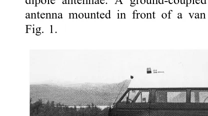
Ž .3 a samplerrrecorder which samples the re-flected signals and converts them into a form for computer storage. The radar antennae in common use fall into two broad categories: air-launched horn antennae and ground-coupled dipole antennae. A ground-coupled 500 MHz antenna mounted in front of a van is seen in Fig. 1.
Ž .
Ground-coupled antennae operate in a wide range of central frequencies from 80 to 1500 MHz. The clear advantage of ground-coupled systems is their depth of penetration compared with air-launched systems, while the surface coupling and antenna ringing present problems, which make it difficult to obtain any quantita-tive information from the near surface without signal processing. Data collection speed with ground-coupled systems is normally 5–15 kmrh. The leading manufacturer of ground-coupled systems is GSSI of New Hampshire, USA, other manufacturers include Sensors and
˚
Software from Canada and MALA from Swe-den.
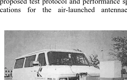
Air-launched systems operate in the range of 500 MHz–2.5 GHz, the most common central frequency being 1.0 GHz. Their depth penetra-tion is typically 0.5–0.9 m. During the data acquisition these antennae are suspended 0.3– 0.5 m above the pavement surface. The data collection speed can be up to 100 scansrs which allows GPR survey velocities up to 100 kmrh. Currently three vendors from the USA manufacture and sell air-launched systems: GSSI of New Hampshire, Penetradar of New York, and Pulse Radar of Texas. Fig. 2 presents TTI Penetradar air-launched horn antenna.
In order to promote efforts for better GPR
Ž .
hardware systems, Scullion et al. 1996 have proposed test protocol and performance specifi-cations for the air-launched antennae and
Ž .
Fig. 2. Texas Transportation Institute TTI GPR survey van with Pulse Radar 1.0 GHz horn antenna.
ground-coupled antennae with higher frequen-cies than 500 MHz.
In the future, the road GPR hardware devel-opment will go towards smaller non-contact antennae and multichannel data collection sys-tems, which allow tomographic images from the road. One example of these systems is the 64-channel HERMES bridge inspector under devel-opment by the Lawrence Livermore National
Ž .
Laboratory Davidson and Chase, 1998 .
2.2. Software
The GPR software available for road surveys
Ž .
can be classified into four groups: 1 GPR data
Ž .
acquisition software, 2 GPR data processing
Ž .
software, 3 interpretation and visualization
Ž .
software, and 4 software for integrated road analysis and design.
Most of the GPR data acquisition software has been developed by the GPR systems manu-facturers. However, custom built data collection and quality control software packages are now being developed. Improved packages are needed when air-launched horn antenna systems are used for pavement quality control purposes, where measurements have to be repeatable and where the GPR results will be used determine bonuses and penalties on newly completed pro-jects.
A very important feature in data acquisition software is the linkage to the positioning sys-tems, such as GPS, because modern pavement
Ž .
management systems PMS pavement design software need information to be attached to
x, y, z coordinates. Currently, most systems are
using a distance based data acquisition control. In the next few years exact positioning and linking of GPR data to other pavement survey data is one key research area.
( )
T. Saarenketo, T. ScullionrJournal of Applied Geophysics 43 2000 119–138
122
requires only basic signal filtering and back-ground removal algorithms. A challenge in the future in data processing software is to infer some quantitative information on electrical properties of the pavement layers and subgrade.
Ž
Spagnolini Spagnolini, 1996; Spagnolini, 1997;
.
Agosti et al., 1998 has approached this problem by investigating promising techniques to resolve some of the essential problems in road structure evaluation, i.e., inversion technique to gain in-formation about vertical distribution of dielec-tric value in road structures and layer stripping technique to define the exact location of the reflections when overlapping each other.
GPR data interpretation and visualization software for roads are used for detecting layer interfaces and individual objects from the GPR data and transforming the GPR data time scale into depth scale. Many efforts, including the use of neural networks, have been made in order to develop automatic interpretation software for roads and bridges. However, the results of these development projects have not been encourag-ing and have caused confusion among highway engineers. The reason for automatic interpreta-tion software packages will most likely never work is that the roads are mostly historical structures with ‘‘accumulation and deteriorated structures’’ and discontinuities in longitudinal, vertical, and transverse directions. That is why semiautomatic interpretation software used by well trained and experienced interpreting staff together with limited coring or other reference survey results has proved to be the only work-ing solution in road surveys. The user must also ensure that the echoes are from real interfaces and not the result of multiple reflections be-tween strong reflectors by comparing the echo profiles of the interface in question with those nearby. The only cases where automatic inter-pretation seems to calculate right thickness and dielectric values are surveys on new and defect free pavements. More discussion on this will be given in Section 5.
A new generation among GPR software are the integrated road analysis and design software
packages, which are designed for the combined analysis of GPR data with other road survey data, with the ability to calculate parameters which describe the condition of the old road, and parameters needed for a new road structure
Ž .
or rehabilitation design Saarenketo, 1999 . In road surveys GPR data output are presented in numeric format or they are visualized in longi-tudinal profiles or GIS maps. In many cases the actual GPR data is not presented, only the re-sults are visualized. When combined with other data types such as longitudinal profile, the GPR is used to identify the potential cause of surface defects.
3. Road subgrade surveys
3.1. General
Subgrade surveys and site investigations with GPR has been classified into the following three
Ž . Ž .
categories Saarenketo and Scullion, 1994 : 1
Ž .
new road alignment and site investigations, 2 strengthening and widening of an existing road,
Ž .
and 3 using the existing road as an informa-tion source for the design of a new roadway alongside the existing road. In each case the basic problem is similar, but the way the GPR techniques are applied varies.
In subgrade surveys for a new road align-ment, GPR can be used to determine the soil types and their boundaries, estimating the depth of bedrock, and evaluating the ground water
Ž .
level and frost susceptibility Saarenketo, 1992 . GPR data can be used also for guidance of conventional site investigations such as drilling and, in places which cover the variety of geo-logical conditions, to optimize the use of these traditional methods. Low frequency ground-coupled systems are used for this application.
techniques have been used also for detecting
Ž .
scours around bridge piers Haeni et al., 1992 . In road rehabilitation projects and when de-signing a new road alignment alongside the old roadway, most of the previously mentioned in-formation is collected from the subgrade under the existing road. These subgrade data, com-bined with other GPR data collected from the existing road layers, provide valuable informa-tion that can be used for predicting the perfor-mance of the new road.
3.2. Subgrade soil eÕaluation
It is often quite easy to identify coarse grained gravel, sand and glacial till soils from GPR data and GPR works well with organic peat soils
ŽUlriksen, 1982; Doolittle and Rebertus, 1988; Ground Penetrating Radar, 1992; Saarenketo et
.
al., 1992 . GPR signals have relatively good signal penetration in most silty soils, but prob-lems arise when surveys are carried out in clay soils. In Scandinavia, GPR signal penetration in clay soil areas is normally about 2 m, which is adequate for the cable and pipeline surveys but not for the highway design purposes. In such cases other geophysical methods, such as elec-trical resistivity profiling methods, have been applied.
In the USA, the penetration depth depends on the mineralogy and clay content of clay soils. A penetration depth of 5 m has been achieved in areas of Site Oxidic soils, while radar signals penetrate only 0.15 m in Vaiden type
Montmo-Ž .
rillonitic soils Doolittle and Rebertus, 1988 .
Ž .
According to Doolittle 1987 the best areas in the USA for radar in soil surveys are eastern and western states, while the greatest problems occur in the Mississippi–Missouri drainage basin area in the central states.
In many cases the soil type can be deter-mined from the GPR data, because every soil has its own geological structure, dielectric, and
Ž
electrical conductivity properties see
Saaren-.
keto, 1998a ; these properties cause a special ‘‘finger print texture’’ in a GPR profile. In
Finland, for instance, soils that have dielectric dispersion tend to have a special ‘‘ringing’’ GPR reflection pattern whereas soils with no dispersive fine grained materials do not have this phenomenon. This knowledge has been ap-plied especially when doing sand and gravel
Ž .
aggregate prospecting Saarenketo, 1992 . Soil type evaluations always need some ground truth data to confirm the GPR interpretation. A very helpful technique for interpreters is to attach drill core information to the GPR profile, which helps to select the right reflection interfaces for the final interpretation, as shown in the case study conducted in TH 28 Burtrum in
Min-Ž . Ž .
nesota Saarenketo, 1998b Fig. 3 . In this figure strong reflectors between 300–370 m and 410–480 m present old road surface levels that have settled due to highly compressive peat subgrade. Excellent supporting information can also be gained from the Falling Weight
Deflec-Ž .
tometer FWD survey data.
3.3. Depth to bedrock and bedrock quality
In road surveys GPR information of the depth of overburden and location of the bedrock is used in the design of grade lines, or in design against uneven frost heave and other specific technical problems such as in backcalculation of pavement layer moduli. GPR allows also obser-vation of bedrock stratification and major frac-ture zones when evaluating the stability of
high-Ž .
way cutting walls Saarenketo, 1992 . Similar information can also be obtained in highway tunnel surveys where both ground-coupled and
Ž
drill-hole antennae have been used Westerdahl
.
et al., 1992 .
( )
T. Saarenketo, T. ScullionrJournal of Applied Geophysics 43 2000 119–138
124
Fig. 3. 400 MHz ground-coupled antenna survey result from TH 28, Burtrum, Minnesota presented with interpretation and
Ž .
reference drill data Saarenketo, 1998b .
if the bedrock has been blasted under the road to a certain level, the transition zone from bedrock to road structures may be wide and no clear discrete interface reflection can be
ob-Ž
served in the radar trace Saarenketo and
Scul-.
lion, 1994 . That is also the case in areas of weathering crust over bedrock. In all of these cases, the estimation of bedrock interface has to be done by identification of the zone in the radar profile where the bedrock structure starts. In highway engineering the bedrock is de-fined as a stiff material that cannot be excavated without blasting. Because GPR gives structural information, the survey data always needs some supporting information and reference data, such as drilling, excavation pits or seismic survey data. A very promising and economical tech-nique in road surveys has been the analysis of the GPR data together with the FWD data
ŽSaarenketo, 1999; Scullion and Saarenketo,
.
1999 . If the bedrock is close to the surface it can be seen in the FWD deflection bowl data. The depth can be confirmed by using FWD backcalculation algorithms. Once the depth to
the stiff layer has been calculated from the FWD measurement point, the surface of the bedrock between the FWD measurement points can be defined from the GPR data as done in Rd
Ž .
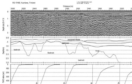
17469 in Kuortane, Western Finland Fig. 4 . If GPR surveys are performed in the wintertime, the areas of the bedrock closer to the surface than the frost level are easy to identify because the frost line reflection in the bedrock cannot be
Ž .
seen from the radar profile Fig. 4 .
3.4. Soil moisture and frost susceptibility
Moisture content has a great effect on the strength and deformation properties of the road structure and subgrade soils. Information about the subgrade soil moisture content is needed in estimating stability and compressibility of the subgrade soils, when designing highways on areas with expansive clays and when evaluating frost susceptibility of soils.
Fig. 4. 500 MHz ground-coupled data collected from Rd 17469, Kuortane, Western Finland. Measurements were performed in May 1998 when the subgrade was still partly frozen. GPR data is presented together with FWD data. Clear reflections in section 2140–2240 at depth of 1.4 and 2.0 m present upper and lower interface of the frost table.
soils and unbound road structures the term ‘‘suction’’ is used for the thermodynamic quan-tity, Gibbs free energy, which generates tension in the pore water between soil particles. The total suction is composed of two components:
Ž .1 matric suction and Ž .2 osmotic suction
ŽFredlund and Rahardjo, 1993 . The magnitude.
of the matric suction is mostly affected by the amount of fines in soils, while cation exchange
Ž .
capacity CEC and salt content affect the os-motic suction.
In low moisture contents, suction can in-crease the stiffness of soils and unbound aggre-gates and they have high modulus values, but when moisture content increases, suction
de-Ž .
creases Fredlund and Rahardjo, 1993 . At high moisture content, positive pore water pressure can decrease the material resistance to perma-nent deformation.
In the case of widening andror strengthening an existing highway, or when constructing new lanes, the best information about the changes in compressibility of the subgrade soil can be ob-tained directly by surveying the existing road with GPR. This technique is especially useful when estimating the amount of settlements in new road and when designing preloading em-bankments over clay, silt or peat subgrade
ŽSaarenketo et al., 1992 . A good example illus-.
trating the information obtained from an old road is the case study conducted on HW 170
Ž .
near Helsinki, Finland Fig. 5 .
re-( )
T. Saarenketo, T. ScullionrJournal of Applied Geophysics 43 2000 119–138
126
¨
Fig. 5. GPR data from HW 170 Ostersundom near Helsinki, Finland. The section of settled road can be seen between 4440 and 4620 m, where the old concrete road constructed in 1930s lies at the depth of 1.5 m. The bridge presents the level where the road was originally constructed.
lated to subgrade soil and moisture transition areas, or to the presence of bedrock or boulders. Structural elements in the road body, such as culverts, have also caused surface damage if the transition wedges are not properly constructed.
Frost susceptibility is also closely related to the moisture content and drainage character-istics of the subgrade, which can be estimated with GPR and other dielectric measurement de-vices, such as the Percometer technique.
Saaren-Ž .
keto 1995 has proposed a frost susceptibility
and compressibility classification for the sub-grade soils in Finland, which is based on in situ measurements of dielectric value and electrical conductivity.
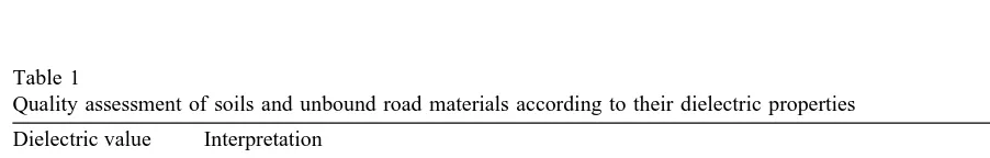
A tentative quality assessment of the strength and deformation properties of soils and unbound road materials based on the dielectric properties
Ž
is presented in Table 1 see also Hanninen and
¨
.
Sutinen, 1994; Hanninen, 1997 .
¨
The evaluation of potential frost action areas and presence of segregation ice using GPR can
Table 1
Quality assessment of soils and unbound road materials according to their dielectric properties Dielectric value Interpretation
Ž .
4–9 Dry and non-frost susceptible soil, in most cases good bearing capacity excluding some sands 9–16 Moist and slightly frost susceptible soil, reduced but in most cases adequate bearing capacity 16–28 Highly frost susceptible and water susceptible soil, low bearing capacity, under repeated dynamic
also be performed in winter time when frost has penetrated into the subgrade soil and when the dielectric value of frozen soils is closer to the
Ž
relative dielectric value of frozen water 3.6–
.
4.0 . When analyzing the GPR data the inter-preter has to pay attention to the following
Ž .
phenomena: 1 the appearance of the
Ž .
frozenrnon-frozen soil interface reflection, 2 the depth of frost table and clarity of the
reflec-Ž .
tion, and 3 the effect of the frost action upon
Ž
the road structures Saarenketo, 1995, 1999;
.
Saarenketo and Scullion, 1994 .
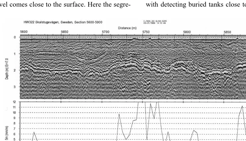
If the frost level cannot be identified from the radar data, then the subgrade soils have a low dielectric value and thus are non-frost suscepti-ble. If the frost level reflection is very clear in the GPR data, then the frost has penetrated the subgrade without forming segregation ice lenses that cause frost heave. High and uneven frost heave can be found in areas where the frost level comes close to the surface. Here the
segre-gation ice containing unfrozen water can be seen in the GPR data above the frost level as in the case from HW 322 Skalstugavagen in West-
¨
Ž .
ern Central Sweden Fig. 6 .
3.5. Other subgrade related surÕeys
GPR techniques have also been used when
Ž
locating sinkholes under the road Saarenketo
.
and Scullion, 1994; Casas et al., 1996 . Adams
Ž .
et al. 1998 have reported surveys results where GPR has been used to detect the washout of sandy material beneath the pavement in IS 44, Springfield, MO. After locating the area of voids, GPR has also been used to monitor the
Ž
grout injection into the voids see also Ballard,
.
1992 . Another GPR application related to the subgrade surveys is the location of underground
Ž
utilities under the existing road Bae et al.,
.
1996 . Numerous authors have also had success with detecting buried tanks close to the edge of
Fig. 6. 500 MHz ground-coupled data collected in March 1998 from HW322 Skalstugavagen, Sweden presented together¨
Ž .
( )
T. Saarenketo, T. ScullionrJournal of Applied Geophysics 43 2000 119–138
128
the existing pavement structure prior to widen-ing of the highway.
4. Road structure evaluation
4.1. General
In highway engineering a potential major growth area for GPR applications will be in the evaluation of existing road structures. This is because the basic road network in the industrial-ized world is now almost complete and the activities of national road authorities will be increasingly focused on maintaining and im-proving the service standards of their current road network. At the same time national road administrations have faced the fact that public funding has decreased markedly. That is why new maintenance strategies and rehabilitation techniques are needed to optimally allocate the shrinking available funds. GPR can certainly play an important role in this area, it is the only technology that can be used at highway speed to provide subsurface information about the pave-ment structure. Combining GPR with other non-destructive road survey techniques provides a powerful tool for diagnosing current pavement problems and selecting the optimum repair
tech-Ž .
nique Saarenketo, 1999 .
In pavement structure evaluation, both ground-coupled and air-coupled antennae sys-tems are used. Most of the ground-coupled an-tennae surveys are conducted using 400–500 MHz antennae in order to get information from the whole pavement structure up to 3 m, but high frequency 1.5 GHz ground-coupled anten-nae have been used to locate stripping and other
Ž .
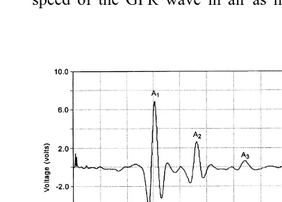
defects in pavement Saarenketo, 1998c . The air-launched GPR systems are increas-ingly being used for evaluation of the upper part of the pavement structure. They produce rela-tively clean signals and can operate at close to highway speed. Furthermore, on defect free pavements the signals can be processed to com-pute both layer thicknesses and layer dielectrics.
This is demonstrated in the following, with reference to Fig. 7 which shows a GPR reflec-tion from a homogeneous newly constructed flexible pavement. The reflections A , A and1 2
A are reflections from the surface, the top of3
granular base and the top of subgrade, respec-tively. The principles of using GPR reflections to compute layer properties has been given by
Ž .
Maser and Scullion 1991 . By automatically monitoring the amplitudes and time delays be-tween peaks, it is possible to calculate both layer dielectrics and thicknesses. These equa-tions are summarized below:
2
1qA1rAm
´ s ,
Ž .
1a
1yA1rAm
where, ´ sthe dielectric value of the asphalt a
surfacing layer; A1sthe amplitude of the
re-Ž
flection from the surface in volts peak A in1 .
Fig. 7 ; Amsthe amplitude of the reflection
Ž
from a large metal plate in volts this represents
.
the 100% reflection case .
c=Dt speed of the GPR wave in air as measured by
Fig. 7. GPR trace from a new pavement measured with a 1.0 GHz horn antenna and after background removal. Peaks A , A , and A are reflections from road surface,1 2 3
the system;Dt sthe time delay between peaks 1
A and A of Fig. 71 2 2
A1 A2
1y q
Am Am
´ s ´ , 3
(
b(
a A AŽ .
1 2
1y q
Am Am
where, ´ sthe dielectric of the base layer; b
A2sthe amplitude of reflection from the top of the base layer in volts.
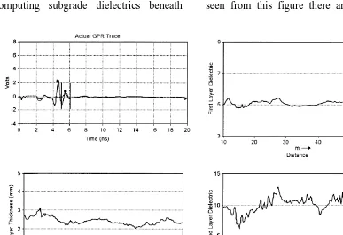
These simple equations have been proven to work well for flexible pavements over granular bases. They assume that no attenuation of the GPR signal occurs in the surface layer. This assumption appears to be reasonable for asphalt pavements and also gives reasonable dielectric values for base layer, if the asphalt is thicker than 60 mm and there are no also thin layers on the top of the base. However, the computations become less reliable for concrete pavements and for computing subgrade dielectrics beneath
granular base layers. Current research activities are aimed at incorporating signal attenuation into the calculation process.
For new or defect free pavements, the surface and base dielectrics together with the surface thickness can be easily calculated. Current work in Texas and Finland is aimed at performing these calculations in real-time primarily for quality control purposes. The results for a sec-tion of highway are often displayed as shown in Fig. 8. It is the magnitude and variation of both the surface and base dielectric which yields substantial information about subsurface condi-tions. The factors which primarily impacts the surface dielectric is the density of the asphalt layer, the factor impacting the base dielectric is the volumetric moisture content of the base. The GPR reflections can also be used to judge the homogeneity of the pavement layers. The reflec-tions shown in Fig. 7 are from a defect free homogeneous pavement structure. As can be seen from this figure there are no reflections
( )
T. Saarenketo, T. ScullionrJournal of Applied Geophysics 43 2000 119–138
130
between the reflections from the top of the surface and base. If the layer contained a defect at middepth such as stripping or trapped mois-ture then additional reflections would occur be-tween peaks A and A .1 2
4.2. PaÕement thickness
The GPR pavement thickness data has been
Ž .
collected for: a network level surveys where thickness is required for PMS data bases
ŽFernando et al., 1994 , b to supplement FWD. Ž . Ž
data in calculation of layer moduli Briggs et
. Ž .
al., 1991 , c pavement design purposes, e.g., to check if the pavement is thick enough for
Ž .
recycling milling, and d for quality control
Ž
purposes Saarenketo and Roimela, 1998;
Scul-.
lion and Saarenketo, 1998 .
Using the techniques described above for new pavements the accuracy of GPR thickness pre-dictions has been around 3–5%, without taking a validation core. For the base layer, the accura-cies have been reported to be close to 8–10%. For older pavement, validation cores are
recom-Ž
mended Maser and Scullion, 1991; see also
.
Morey, 1998 .
4.3. PaÕement defects
Even though a greatest part of the defects observed on asphalt pavements are related to material problems of the layers beneath the pavement, there are also some pavement dam-ages caused by deterioration problems inside the pavement. The most common asphalt pavement damage is stripping, which is a moisture related mechanism where the bond between asphalt and aggregate is broken leaving an unstable low density layer in the asphalt. Stripped layers should always be detected and removed before placing a new overlay. That is why engineers responsible for in-pavement design should know if stripping is present or not, how deep and how widespread it is.
GPR technique has been widely used to
de-Ž
tect stripping with varying success see Morey,
.
1998 . Stripping can be bee seen in most cases
Ž
as an additional positive or negative reversed
.
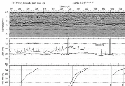
reflection polarity reflection in the pavement. However, similar reflection can be received from an internal asphalt layer with different electrical properties, which is why reference data, such as drill cores and FWD data should always be used to confirm the interpretation. Fig. 9 presents a case from Willmar, Minnesota, where 1.5 GHz ground-coupled and FWD data were used to
Ž .
evaluate stripping Saarenketo, 1998c .
Another major cause of surface distress is moisture becoming trapped within the surface layer. This happens when impermeable fabrics or chip seals are placed between asphalt layers or when the existing surface is milled and re-placed with a less dense layer. GPR signals are highly sensitive to variations in both moisture and density. In a recent study in Texas, five types of reflections were identified from within asphalt surfacing. These are shown schemati-cally in Fig. 10. The ‘‘ideal’’ trace with little contrast between the new and old Hot Mix
Ž .
Asphalt HMA is defined as a Case 1 reflection in Fig. 10, a small reflection B1 is proposed from the interface between the new and old HMA layers.
GPR reflections from existing highways can be complex particularly if the old HMA layer contains numerous thin layers constructed with different aggregates compacted to different den-sities. Moisture barriers within the layer and collecting data shortly after significant rain can also complicate the analysis. Fig. 10 was devel-oped to aid in signal interpretation.
Other asphalt defects include cracking
ŽSaarenketo and Scullion, 1994 , thermal crack-.
ing and debonding, which takes place when the bonding between separate asphalt layers comes loose.
Fig. 9. 1.5 GHz ground-coupled antenna data collected from TH71 Willmar, Minnesota presented with FWD data. The road section with severe stripping on the bottom of the asphalt between 900 and 990 m can be seen both with GPR and FWD data.
Ž .
stabilized bases Saarenketo and Scullion, 1994 . Over time, bases erode and supporting material is frequently pumped out under the action of truck loads.
The problem when using GPR to detect the voids beneath concrete slabs is the moisture content of the voids, i.e., depending on whether the voids are dry, semidry or saturated, in each case the GPR reflection pattern looks different. The size of the voids has to be big enough; GPR can detect only voids bigger than 15 mm
ŽSaarenketo and Scullion, 1994 ..
4.4. Base course and unbound road structures
Base course layer made of unbound aggre-gates which supports asphalt or concrete pave-ment is one of the most critical layer in road structure. A series of research projects have
been carried out in Finland and Texas where the relationship of dielectric properties of Finnish and Texas base materials to their water content and to their strength and deformation properties
Ž
were studied with a DCP Dynamic Cone
Pene-.
tration test and dynamic triaxial tests
ŽSaarenketo and Scullion, 1995, 1996;
Saaren-.
keto et al., 1998 . A special Tube Suction labo-ratory test based on the dielectric measurements of the material at its moisture equilibrium level has also been developed in order to test the moisture susceptibility of road materials
ŽSaarenketo and Scullion, 1995; Scullion and
.
Saarenketo, 1997 .
( )
T. Saarenketo, T. ScullionrJournal of Applied Geophysics 43 2000 119–138
132
Fig. 10. Classification and interpretation of different sub-surface reflections from asphalt layers containing a buried
Ž .
moisture barrier chip seal or fabric .
bound water’’ exists in materials, is a much better indicator of the strength and deformation properties of road aggregates than the moisture content. Each aggregate type has a unique rela-tionship between material dielectric and
mois-Ž .
ture content. As shown in Eq. 3 , the amplitude of the GPR reflection from the top of the granu-lar layer is used to calculate the dielectric of that layer. Furthermore, high dielectric values
Ž)16 , calculated from the GPR data, for ex-.
ample, are good indicators for potential
prob-Ž .
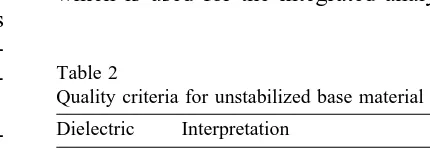
lems in the layer Saarenketo et al., 1998 . A tentative quality assessment scale for un-stabilized flexible base is proposed in Table 2.
4.5. Project leÕel surÕeys and road analysis
One of the best fields for the applications of GPR technology is in the project level testing
for pavement management purposes. Identifying the cause of existing problems and defining the optimal rehabilitation strategy is an area of criti-cal importance. GPR alone can provide only a part of the answer, but it becomes more power-ful when combined with other geophysical and non-destructive pavement testing methods. In Texas, GPR data has been analyzed together with FWD structural data, pavement distress data from the video image and drill core data
ŽScullion and Saarenketo, 1999 . Integrated.
analysis techniques has also been applied in airports where GPR data has been analyzed together with infrared thermography, magne-tometer and pachometer measurement data
ŽWeil, 1998 . Case studies of GPR in project.
level surveys has been published by
Hugen-Ž . Ž .
schmidt et al. 1996 and Wimsatt et al. 1998
Žsee also Morey, 1998 ..
In Finland, a comprehensive Road Analysis package has been developed by Roadscanners Oy in cooperation with Finnra. It includes an
Ž .
evaluation of: 1 overall pavement condition,
Ž .2 condition assessment of the unbound
pave-Ž .
ment structure, 3 subgrade damage related to
Ž . Ž .
frost fatigue, 4 drainage condition, and 5 local damage of the surveyed road. The analysis is based on measurements conducted with GPR, with the support of drill core samples, rough-ness and rutting measurements with 5 or 10 m
Ž .
mean value 5 m-IRI , FWD measurements, and visual observations of pavement surface condi-tion.
A key tool in Road Analysis is the Road Doctor software developed by Roadscanners Oy, which is used for the integrated analysis of the
Table 2
Quality criteria for unstabilized base material Dielectric Interpretation
5–10 Good aggregate base at or below optimum moisture content 10–16 Warning signal, wet base )16 Plastic base susceptible to load
pavement structure. In the first phase, Road Doctor processes the ground-coupled and air-coupled GPR data and the thickness of the asphalt and other structural layers are calcu-lated. In the next phase, FWD rutting and roughness survey data are imported to the Road Doctor database together with other reference
Ž .
data such as drill core information Fig. 11 . If
x, y, z information of the road under survey is
available, the GPR data can be viewed with topography information and all the layer inter-face information can be transferred to a road CAD systems together with the coordinates. In the Road Analysis, the road is divided into homogenous sections and classified according to the subgrade soil quality and effect of the freeze–thaw process to the road structures. Also
structural course thickness and material proper-ties are evaluated. As a result of a detailed Road Analysis of the road structure, the quality and extent of the damages in road structures are reported to the pavement engineer in order to provide reliable information to support rehabili-tation design decisions.
5. Quality control of a new structure
5.1. General
Nondestructive pavement testing methods, such as GPR, have gained increasing popularity in quality control surveys of new road struc-tures. The greatest advantages of GPR methods
( )
T. Saarenketo, T. ScullionrJournal of Applied Geophysics 43 2000 119–138
134
are that they are not destructive when compared to the traditional drill core methods, they are low cost methods and GPR surveys can also be performed from a moving vehicle reducing safety hazards to highway personnel. GPR al-lows for the possibility for continuous data col-lection and thus a 100% coverage can be ac-quired from the new road structure under in-spection. Drill core methods provide point spe-cific information and they cannot be reliably used to find defect areas in new pavements.
The GPR applications in quality control sur-veys include thickness verification of the road structures. This technique has been discussed earlier in Section 4.2. GPR has also been used to check if the soil replacement and transition wedges are constructed according to instructions and if dowel bars between concrete slabs have been installed properly. New GPR quality con-trol applications include measuring the air voids content of asphalt and detecting segregation in asphalt.
5.2. Asphalt airÕoid content
Asphalt air void content, i.e., the amount of air incorporated into the material or its function asphalt density, is one of the most important factors affecting the life span and deformation properties of pavements. This parameter has earlier been estimated by means of drilled sam-ple analysis or radioactive methods, but after 3 years of testing the GPR surface reflection tech-nique, it has also been accepted as official
Ž
quality control method in Finland Saarenketo, 1997; Saarenketo and Roimela, 1998; Roimela,
.
1998, 1999 .
Measuring voids content using its dielectric value relies on the fact that the dielectric value of the asphalt pavement is a function of volu-metric proportions of the dielectric values of its components. Compaction of the asphalt reduces the proportion of low-dielectric value air in the asphalt mixture and increases the volumetric proportions of bitumen and rock and thus results in higher dielectric values of asphalt. The
rela-tionship between dielectric value of asphalt and air voids content measured in the laboratory is presented in Fig. 12.
The GPR measurements in the field are per-formed using a 1.0 GHz horn antenna. Dielec-tric values of HMA surfacing are calculated by using the surface reflection techniques described earlier. Following the GPR field evaluation one or two calibration cores are taken. These cores are returned to the laboratory for traditional void content determination. Long term studies in Finland have concluded that an exponential relationship exists between surface dielectric and air void content. For each type of aggregate and mix design, similarly shaped relationships have been developed. The calibration cores are used to establish the link for each specific project. The correlation between air void content mea-sured with GPR technique and air void content using laboratory results is presented in Fig. 13. These results are obtained from a comprehen-sive series of field surveys conducted in Finland
Ž .
in 1997 Saarenketo and Roimela, 1998 . These
Ž
results and additional survey results Roimela,
.
1998, 1999 have convinced Finnra that GPR is a viable tool for monitoring the quality of new HMA surfacing. In 1999, GPR can be used as a quality control tool among other pavement den-sity measurement techniques on all new surfac-ing projects in Finland.
Fig. 13. Asphalt void content measured with GPR in the field versus void content measured in the laboratory.
5.3. Segregation
One of the major functions of Hot Mix Sur-facing on highways is to provide waterproofing for the underlying structural base layers. If ex-cessive moisture can enter the base layer, then rapid load and environmental damage will oc-cur. The surfacing layer will only function as intended if it is compacted to optimum density, it does not contain any defects such as areas of segregation, and if the longitudinal construction joints are waterproof. Segregation manifests it-self as localized periodic small areas of low density material in the compacted surfacing layer. Upon close inspection in these small lo-calized areas, an excess of coarse aggregates is found. The causes are often traced to improper handling or construction techniques. During construction, the segregated areas are often im-possible to detect visually; they only become apparent after 1 or 2 months in service. How-ever, these areas often have a major impact on long term pavement performance. The segre-gated areas are often sources for moisture to enter the lower pavement layers. The asphalt industry is well aware of the segregation prob-lem and in the past decade, several new con-struction techniques have been implemented in-cluding the use of Materials Transfer Vehicles as part of the paving train. Despite progress in this area, segregation is still a major concern
and at the present time, there are no ways of detecting these problems during construction. A second problem area is that of the permeability of longitudinal joints.
GPR offers tremendous potential to assist in monitoring the quality of the completed surfac-ing layer. The GPR parameter which can detect these problem areas is the surface dielectric. GPR traces can be collected at closely spaced intervals, and with minimal data processing, a plot of surface dielectric versus distance can be produced. The dielectric of the surface layer is a function of the dielectric of the component
ma-Ž .
terials aggregate, air and asphalt and their volumetric ratios. If an asphalt surface is uni-formly compacted, the surface dielectric should be constant; however, if a low permeability area has excessive air voids, this will be observed in the surface dielectric plot as a decrease in mea-sured dielectric.
The first use of GPR technology to monitor the quality control of pavements was reported
Ž .
by Saarenketo 1997 . Large changes in the surface dielectric were attributed to the use of an experimental paver. Fig. 14 shows surface dielectric plots taken over longitudinal construc-tion joints in Texas. The vehicle was travelling along the highway and made three transitions over the longitudinal joint between the lanes. As can be seen further away from the joint, the surface dielectric is relatively constant at around
( )
T. Saarenketo, T. ScullionrJournal of Applied Geophysics 43 2000 119–138
136
5.5, whereas over the joint, the value is closer to 4.5. Research studies are underway in both Texas and Finland to relate the change in sur-face dielectric to changes in both air voids and mix permeability.
6. Future developments
Even though the history of the GPR applica-tions in roads and highways is relatively short, the method has proven to be a very useful tool to solve various kinds of highway engineering problems. The life cycle of the GPR applica-tions on roads are still on the introduction phase in most of the highway agencies. Awareness and education are still needed to get diffusion and adoption for the method.
A very important factor in the future of GPR in road surveys is to establish the technique in routine road analysis and pavement rehabilita-tion and design procedures. The status of radar as an interesting but obscure method for specific pavement survey projects should be changed to a routine road survey tool that is used among other survey techniques. For that to occur, cer-tain standards and specifications for GPR equip-ment, data acquisition and interpretation tech-niques will be needed.
Even though this paper has described the GPR technique on roads and presents some successful cases, there are unfortunately several failures that have been reported around the world. These are usually attributed to over-sell-ing the technology by vendors who understand GPR but do not appreciate the complexity of the pavement systems. The best hope for the future
Ž .
involves three critical steps: 1 developing user-friendly software packages in order to con-vert the GPR data with other road survey data into information which is meaningful to
pave-Ž .
ment engineers, 2 gaining an understanding of the electrical properties of road materials and subgrade soils and their relation to the moisture
Ž .
and strength and deformation properties, and 3
provide training for highway agencies and other customers who are using the GPR data and for the staff who are responsible for GPR surveys. When these steps have been accomplished, GPR techniques and applications will have huge mar-kets in road design, construction and mainte-nance industry.
References
Adams, G., Anderson, N., Baker, J., Shoemaker, M., Hatheway, A., 1998. Ground-penetrating radar study of subsidence along U.S. interstate 44, Springfield, MO. In: Proceedings of the Seventh International Confer-ence on Ground Penetrating Radar, May 27–30, Lawrence, KS, USA, pp. 619–623.
Agosti, S., Spagnolini, U., Gentili, G.G., Rampa, V., 1998. Electromagnetic inversion and interface tracking: sys-tem calibration and application. In Proceedings of the Seventh International Conference on Ground Penetrat-ing Radar. May 27–30, Lawrence, KS, USA, pp. 607– 612.
Alongi, T., Clemena, G.G., Cady, P.D. 1992. Condition Evaluation of Concrete Bridges relative to Reinforce-ment Corrosion, Vol. 3, SHRP Report SHRP-SrFR-92-105, Washington, D.C.
Bae, S.H., Kim, H.S., Yoon, W.S., 1996. Cases studies on the application of ground penetrating technology in detection of underground utilities and structure safety diagnosis. In: Proceedings of the Sixth International Conference on Ground Penetrating Radar, September 30–October 3, Sendai, Japan, pp. 467–472.
Ballard, G., 1992. Under the Skin. World Highwaysr Routes du Monde. JanrFeb 1992, pp. 37–39.
Berg, F. 1984. Ikke destruktiv maling af lagstykkelser I˚
vejbefastelser. Vejdirektoratet, Statens vejlaboratorium, Notat 157, Denmark.
Briggs, R.C., Scullion, T., Maser, K., 1991. Asphalt thick-ness variation an effect on backcalculation. 2nd Interna-tional Conference on Backcalculation, Nashville, USA. Casas, A., Lazaro, R., Vilas, M., 1996. Detecting karstic cavities with ground penetrating radar at different geo-logical environment in Spain. In: Proceedings of the Sixth International Conference on Ground Penetrating Radar. September 30–October 3, Sendai, Japan, pp. 455–460.
Doolittle, J.A., 1987. Using ground-penetrating radar to increase quality and efficiency of soil surveys. Soil survey techniques. Soil Science Society of America Journal 53, 1806–1812.
Doolittle, J.A., Rebertus, R.A., 1988. Ground-penetrating radar as means of quality control for soil surveys. Transportation Research Board Record 1192.
Fernando, E.G., Maser, K.R., Dietrich, B., 1994. Imple-mentation of ground penetrating radar of network level pavement evaluation in Florida. Proceedings of the Fifth International Conference on Ground Penetrating Radar, Vol. 1 of 3, June 12–16, Kitchener, Ontario, Canada, pp. 351–365.
Fredlund, D.G., Rahardjo, H., 1993. Soil Mechanics for Unsaturated Soils, Wiley, New York, 517 pp.
Ground Penetrating Radar, 1992. Geophysical Survey Methods, the Finnish Geotechnical Society and The Finnish Building Centre, Finland, 64 pp.
Haeni, F.P., Placzek, G., Trent, R.E., 1992. Use of ground penetrating radar to investigate refilled scour holes at bridge foundations, Geological Survey of Finland, Spe-cial Paper 16, pp. 285–292.
Hanninen, P. 1997. Dielectric coefficient surveying for¨
overburden classification. Geological Survey of Fin-land, Bulletin 396, Helsinki, 72 p.
Hanninen, P., Sutinen, R., 1994. Dielectric prediction of¨
landslide susceptibility: a model applied to recent sedi-ment flow deposits. Proceedings of VII IAEG, Lisboa 1, 137–144.
Hugenschmidt, J., Partl, M.M., de Witte, H., 1996. GPR inspection of a mountain motorway — a case study. Proceedings of the Sixth International Conference on Ground Penetrating Radar. September 30–October 3, Sendai, Japan, pp. 365–370.
Johansson, H.G., 1987. Anvanding av georadar I olika¨
vagverksprojekt. Vagverket, Serviceavdelning Vag och¨ ¨ ¨
brokonstruktion, Sektionen for¨ geoteknik, Publ. 1987:59, Sweden.
Maijala, P., Saarenketo, T., Valtanen, P., 1994. Correlation of some parameters in GPR measurement data with quality properties of pavements and concrete bridge decks. Proceedings of the Fifth International Confer-ence on Ground Penetrating Radar, Vol. 2 of 3, June 12–16, Kitchener, Ontario, Canada, pp. 393–406. Maser, K.R. 1994. Highway speed radar for pavement
thickness evaluation. Proceedings of the Fifth Interna-tional Conference on Ground Penetrating Radar, Vol. 2 of 3, June 12–16, Kitchener, Ontario, Canada, pp. 423–432.
Maser, K.R., Scullion, T., 1991. Automated Detection of Pavement Layer Thicknesses and Subsurface Moisture Using Ground Penetrating Radar. TRB paper 1991. Morey, R., 1998. Ground penetrating radar for evaluating
subsurface conditions for transportation facilities. Syn-thesis of Highway Practice 255, National Cooperative Highway Research Program, Transportation Research Board, National Academy Press.
Roimela, P. 1998. Ground penetrating radar surveys in pavement quality control 1996–1997. Tielaitoksen
Ž
selvityksia 4r1998, Rovaniemi, Finland English ab-¨
.
stract , 55 pp.
Roimela, P. 1999. The use of pavement radar in quality control of bituminous pavements. Tielaitos, Konsul-tointi. Tielaitoksen selvityksia 6r1999. Rovaniemi,¨
Ž .
Finland English abstratc , 33 pp.
Saarenketo, T. 1992. Ground penetrating radar applications in road design and construction in Finnish lapland. Geological Survey of Finland, Special Paper 15, pp. 161–167.
Saarenketo, T. 1995. The use of dielectric and electrical conductivity measurement and ground penetrating radar for frost susceptibility evaluations of subgrade soils. Proceedings of the Application of Geophysics to Engi-neering and Environmental Problems. Comp. By R.S. Bell. Orlando, FL, pp. 73–85.
Saarenketo, T., 1997. Using ground penetrating radar and dielectric probe measurements in pavement density quality control. Transportation Research Record 1997, pp. 34–41.
Saarenketo, T., 1998a. Electrical properties of water in clay and silty soils. Journal of Applied Geophysics 40, 73–88.
Saarenketo, T., 1998. Minnesota GPR Project, Report: TH28, Burtrum, District 3. Minnesota Department of Transportation, Office of Minnesota Road Research. Saarenketo, T., 1998. Minnesota GPR Project, Report:
TH71, TH23, Willmar, District 8. Minnesota Depart-ment of Transportation, Office of Minnesota Road Re-search.
Saarenketo, T., 1999. Road analysis, an advanced inte-grated survey method for road condition evaluation. Proceedings of the COST Workshop on Modelling and Advanced testing for Unbound and Granular materials, January 21–22. Lisboa, Portugal.
Saarenketo, T., Maijala, P., 1994. Applications of geophys-ical methods to sand, gravel and hard rock aggregate
Ž .
prospecting in northern Finland. In: Luttig, G.W. Ed. , Aggregates — Raw Materials’ Giant, Report on the 2nd International Aggregates Symposium, Erlangen, Germany, October 22–27, pp. 109–123.
Saarenketo, T., Roimela, P., 1998. Ground penetrating radar technique in asphalt pavement density quality control. Proceeding of the Seventh International Con-ference on Ground Penetrating Radar, Vol. 2, May 27–30, 1998, Lawrence KS, pp. 461–466.
( )
T. Saarenketo, T. ScullionrJournal of Applied Geophysics 43 2000 119–138
138
radar applications on roads and highways. Research Report 1923-2F, Texas Transportation Institute, Col-lege Station, Texas, 36 pp.
Saarenketo, Scullion, 1995. Using electrical properties to classify the strength properties of base course aggre-gates. Research Report 1341-2. Texas Transportation Institute, College Station, TX.
Saarenketo, T., Scullion, T., 1996. Laboratory and GPR tests to evaluate electrical and mechanical properties of Texas and finnish base course aggregates. Proceedings of the Sixth International Conference on Ground Pene-trating Radar, September 30–October 3, Sendai, Japan, pp. 477–482.
Saarenketo, T., Soderqvist, M.-K., 1993. GPR applications¨
for bridge deck evaluations in Finland. Proceeding of the Non-Destructive Testing in Civil Engineering, April 14–16, 1993, The University of Liverpool.
Saarenketo, T., Hietala, K., Salmi, T., 1992. GPR applica-tions in geotechnical investigaapplica-tions of peat for road survey purposes. Geological Survey of Finland, Special Paper 16, pp. 293–305.
Saarenketo, T, Scullion, T., Kolisoja, P., 1998. Moisture susceptibility and electrical properties of base course aggregates. Proceeding of BCRA’98, Vol. 3, July 6–8, Trondheim, Norway, pp. 1401–1410.
Scullion, T., Saarenketo, T., 1997. Using suction and dielectric measurements as performance indicators for aggregate base materials. Transportation Research Board Record 1577, pp. 37–44.
Scullion, T., Saarenketo, T., 1998. Applications of ground penetrating radar technology for network and project level pavement management survey systems. Proceed-ings of the 4th International Conference on Managing Pavements, Durban, South Africa, 17th–21st May 1998. Scullion, T., Saarenketo, T., 1999. Integrating ground pen-etrating radar and falling weight deflectometer tech-nologies in pavement evaluation. Proceedings of the Third ASTM Symposium of Nondestructive Testing of Pavements and Backcalculation of Moduli, June 30th– July 1st 1999, Seattle, WA.
Scullion, T., Lau, C.L., Chen, Y., 1992. Implementation of the Texas Ground Penetrating Radar System, Report No. FHWArTX-92r1233-1, Texas Department of Transportation.
Scullion, T., Lau, C.L., Chen, Y., 1994. Pavement evalua-tions using ground penetrating radar. Proceedings of the Fifth International Conference on Ground Penetrating Radar, Vol. 1 of 3, June 12–16, Kitchener, Ontario, Canada, pp. 449–463.
Scullion, T., Lau, C.L., Chen, Y., 1996. Performance specifications of ground penetrating radar. Proceedings of the Sixth International Conference on Ground Pene-trating Radar, September 30–October 3, Sendai, Japan, pp. 341–346.
Spagnolini, U., 1996. Joint approach of EM inversion and multi-layer detectionrtracking for pavement profiling. In: Proceedings of the Sixth International Conference on Ground Penetrating Radar, September 30–October 3, Sendai, Japan, pp. 443–448.
Spagnolini, U., 1997. Permittivity measurements of multi-layered media with monostatic pulse radar. IEEE Transactions on Geoscience and Remote Sensing 35
Ž .2 , 454–463.
Ulriksen, C.P.F., 1982. Application of Impulse Radar to Civil Engineering. Doctoral Thsesis. Lund University of Technology, Department of Engineering Geology, 179 pp.
Weil, G.J., 1998. Nondestructive testing of airport concrete structures. In Proceeding of the Seventh International Conference on Ground Penetrating Radar, May 27–30, Lawrence, KS, USA, pp. 443–448.
Westerdahl, H.R., Austvik, R., Kong, F.-N., 1992. Geo-radar in tunneling — the tunnel Geo-radar. Geological Survey of Finland, Special Paper 16, pp. 41–45. Wimsatt, A., Scullion, T., Ragsdale, J., ja Servos, S., 1998.