ANNEX: INDIVIDUAL REPORTS
2.1. INVESTIGATION OF OXIDE-DISPERSED-STRENGTHENED STEELS
Author Affiliation Title of the paper
Balagurov, A. Joint Institute for Nuclear Research (JNIR),
Russian Federation
Investigation of Precipitation-Hardened Steels using TOF Neutron Diffraction Coppola, R. National Agency for New
Technologies, Energy and Sustainable Economic Development (ENEA), Italy
Characterization of Y2O3 particle distribution in Oxide Dispersion Strengthened Eurofer steel for nuclear applications by means of small-angle neutron scattering (SANS) and of neutron diffraction
2.2. RESEARCH ON ZIRCONIUM BASED MATERIALS (INCLUDING HYDROGEN UPTAKE)
Bourke, M.A.M. Los Alamos National Laboratory (LANL), United States of America
Neutron scattering activity at Los Alamos National Laboratory
Grosse*, M. Institut für
Materialforschung, Germany
In-situ neutron radiography investigations of the hydrogen re-distribution during DHC
Grosse**, M. Institut für
Materialforschung, Germany
Post-test examination of the hydrogen distribution in zirconium claddings after LOCA tests
Grosse***, M. Institut für
Materialforschung, Germany
Small angle neutron scattering investigations of hydride precipitations in Zircaloy-4
Lehmann*, E. Paul Scherrer Institut,
Switzerland Final report about activities at PSI, Switzerland Santisteban*, J. Comisión Nacional de
Energía Atómica (CNEA);
Santisteban**, J. Comisión Nacional de Energía Atómica (CNEA); Argentina
Crystallographic phases, texture and dislocation densities of ZR2.5%NB pressure tubes at different stages of manufacturing
2.4. RESULTS WITH IRRADIATED MATERIALS Kozlov, A.
Institute of Nuclear Materials, Russian Federation
Examination of austenitic steels microstructure change induced neutron irradiation by using of neutron scattering methods
Beams in China Shikama, T. Tohoku University,
Japan Neutron beam analysis on materials for nuclear applications, being irradiated in fission reactors and having radioactivity Tӧrӧk, G. Wigner Research Institute,
Institute of Solid State Physics. Hungary
Investigation of irradiation RPV and ODS steels by SANS and residual stress
2.5. OPTIMIZATION OF INSTRUMENTS FOR RESIDUAL STRAIN/STRESS MEASUREMENTS
Carr, D. Australian Nuclear Science and Technology
Organisation (ANSTO) Australia
Final report on evaluating residual stresses and internal defects in nuclear materials at the Opal reactor at ANSTO, Australia.
Mikula, P. Nuclear Physics Institute (NPI), Sutiarso, S. National Nuclear Energy
Agency (BATAN) Indonesia
Optimization of Neutron Beam Techniques for Characterization
of Structural Materials
2.6. EFFORTS TOWARDS STANDARDIZATION OF NEUTRON IMAGING Pugliesi, R. Instituto de Pesquisas
Energeticas e Nucleares (IPEN)
Brazil
Improvement of a neutron tomography facility
Radebe, M. South African Nuclear Energy Corp. (NECSA) South Africa
2. RESULTS ACHIEVED
INVESTIGATION OF PRECIPITATION-HARDENED STEELS USING TOF NEUTRON DIFFRACTION
A.M. BALAGUROV, G.D. BOKUCHAVA, V.V. SUMIN, I.V. PAPUSHKIN
Frank Laboratory of Neutron Physics, Joint Institute for Nuclear Research, Joliot-Curie 6, 141980 Dubna, Moscow region
Russia
Email: [email protected]; [email protected]
Abstract.
In the frame of current CRP activity series of austenitic and ferritic dispersion-hardened steels, which are used as various structural reactor components, were investigated using high resolution neutron diffraction. The effect of temperature and duration of heat treatment on the precipitation of dispersion-hardened phase particles, as well as lattice parameter changes and microstrain during high temperature creep was studied.
1. INTRODUCTION
Increasing the strength of constructional materials allows one to reduce the amount of material used in the manufacturing of various machinery parts and mechanisms and significantly increase their lifetime. In addition to improving strength properties during the creation of materials for the nuclear industry (steel, structured alloys, etc.) the actual problem is to improve their radiation resistance too, i.e. to reduce their tendency to embrittlement and vacancy swelling. One of the most promising ways to solve this problem is to use the effect of metal or alloy hardening due to the formation of chemically stable non-metallic dispersed phases of submicron size, which inhibit the dislocations movement in the material. Accordingly, the most important task of material science is to understand the processes that occur during precipitation hardening in steels and alloys that can help to create materials purposefully with the desired mechanical properties.
Precipitation strengthening process can take place in the hardened material as a result of annealing at a certain temperatures or under irradiation. It is well known that the strength, creep resistance and radiation resistance of hardened material depend on the dispersed phase state: the degree of its crystal lattice coherence with matrix lattice, the location of nanoparticles precipitation and their size. In addition, the precipitation of second-phase particles is accompanied by a lattice spacing changes in the matrix phase and, thus, the appearance of microstrain, which has a significant effect on the material characteristics.
Important role in the study of dispersion hardening processes occurring in structural materials play nuclear physics methods and, in particular, the diffraction of thermal neutrons. Constructed in various research centers high resolution neutron diffractometers have unique capabilities to determine the materials microstructure due to the high accuracy of the results, the possibility of analysis of multiphase materials, and especially the deep penetration length of neutrons, which is hundred times greater than the penetration length of X rays.
2.1. Investigation of oxide-dispersed-strengthened steels
2. METHODS AND SAMPLES
2.1. Microstrain studies in precipitation-hardened austenitic steels
The studied cylindrical samples with 6 mm diameter were made from austenitic steels H16N15M3T1 and N26H5T3 with Ni3Ti hardening phase and 40H4G18F2 with VC hardening phase (hereinafter labeled as S1, S2 and S3, respectively). In the initial state, all samples were annealed at 450ºC for 2 hours, and then quenched in water. Then the samples were subjected to aging at different temperatures. Subsequent heat treatment temperature and aging duration were selected taking into account the results of Ref. [1]. In this work the kinetic curves of Ni3Ti precipitation in quenched Fe-Ni-Ti alloy during isothermal annealing were presented. It was also shown that the characteristic size of precipitates during isothermal annealing at 650ºC ranged from 3 to 10 nm when the aging time varied from 2 to 12 hours.
Neutron diffraction experiments for microstrain analysis were conducted on the HRPT instrument [2], operating at the SINQ neutron source in the Paul Scherrer Institute (Switzerland). HRPT is the constant wavelength high resolution diffractometer (with resolution value of Δd/d ≈ 0.001 at the minimum of the resolution curve), which allowed to perform detailed analysis of the microstructural characteristics of the samples.
Before investigating the microstress influence on the radiation resistance as well as modification of microstress under irradiation, it was necessary to clarify the possibility of using high resolution neutron diffraction for these purposes. Correct definition of microstresses in polycrystalline samples on a neutron diffractometer is possible if it has a sufficiently high resolution and its resolution function dependence versus interplanar distance dhkl is well known. Therefore, at first the resolution function of the HRPT diffractometer was investigated. This was done by measuring the diffraction patterns from a standard polycrystalline sample Na2Al2Ca3F14 (NAC), recommended by the International Union of Crystallography for instrument calibration and definition of the resolution function with good accuracy. Thus, using the obtained calibration parameters for further patterns processing from working samples by the help of the Rietveld method it was possible to obtain the precise lattice parameters, as well as the microstrain and the average crystallite size.
In Fig.1 diffraction peak widths for two 40H4G18F steel samples tempered at 600ºС and 700ºС measured on HRPT in comparison with instrument resolution function are shown. As it can be seen from this figure on the HRPT diffractometer the diffraction peak broadening effects can be measured easily and with high accuracy.
For quantitative estimates we use the formula relating the width of the diffraction lines with the characteristics of the microstructure of the material - the microstrain ε = Δa/a0, where a0 is stress-free unit cell parameter, and the characteristic size of coherent scattering domains D. Respective contributions to the peak width are (see, e.g. [3]):
βD = k∙λ/(D∙cosθ), βε = 4∙ε∙tanθ, (1)
analysing a wide range of Bragg angles, one can confidently share them. The experimental practice on HRPT showed that the peak broadening effects can be reliably detected at the microstrain values ε ≥ 10-4 and the average crystallite size of the D ≤ 2000 Å.
FIG. 1. Diffraction peak widths for two 40H4G18F steel samples tempered at 600ºС (squares) and 700ºС (circles)measured with HRPT at λ = 1.494 Å in comparison with instrument resolution function (solid line).
FIG. 2. A typical diffraction pattern from the H16N15M3T1 steel sample (S1) measured on HRPT at λ = 1.1545 Å and processed by the Rietveld method. The experimental points, calculated profile (bottom) and peak positions (vertical bars) are shown. The diffraction peaks correspond to the d-spacing interval 0.55 - 2.15 Å.
30 40 50 60 70 80 90 100 110 120 130 140 0.1
0.2 0.3 0.4 0.5 0.6 0.7 0.8 0.9 1.0
Peak wid
th
, deg
.
2.1. Investigation of oxide-dispersed-strengthened steels
and for steel S3, annealed under the same conditions except at 700ºC, 1 hour and 6 hours. The neutron diffraction patterns were measured at room temperature for two wavelengths of the primary beam (λ = 1.1545 and 1.494 Å). Processing of diffraction data were done according to the Rietveld method using the software package FullProf [5], which has the opportunity to analyze the peak width dependence on the scattering angle and to estimate the contributions to the peak broadening due to lattice microstrain and the average size of the coherently scattering domains. It was found that the size effect contribution to the peak width is negligible, i.e. D >> 2000 Å. Conversely, microstresses contribute significantly and, therefore, in further considerations the peak broadening is attributed to the microstress presence only. All main diffraction peaks in the patterns are indicated in the face-centered cubic space group Fm3m with a lattice parameter a0 ≈ 3.6 Å. A typical diffraction pattern processed by the Rietveld method is shown in Fig. 2.
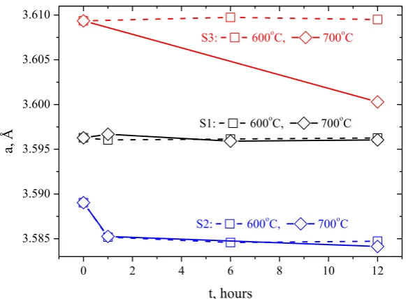
Experimental values of the lattice parameter and microstrain obtained for two neutron wavelengths are in good agreement with each other for each sample; therefore, their average value was used in further considerations. The obtained results are shown in Fig.3 and Fig.4 and in Table 1. The standard deviations for lattice parameters obtained with Full Prof software are very small (the relative error is much smaller than 10-4). Microstrain error values calculation is rather complicated and is not yet implemented in FullProf. The error of the experimental microstrain values was evaluated based on the spread between the results obtained for two different wavelengths, and was about 0.5∙10-4. In Fig. 3, the lattice parameter dependence on the isothermal annealing duration for all three steels is shown. It can be clearly seen that except for the point 700°C for S3 sample depending on the parameter of temperature and time of annealing does not have any features, so here only the behavior of microstrain in the samples is analysed.
FIG. 3. Lattice parameter changes versus isothermal annealing time. The lattice parameter value for the initial state is shown at t=0. Error bars for data points are smaller than symbols.
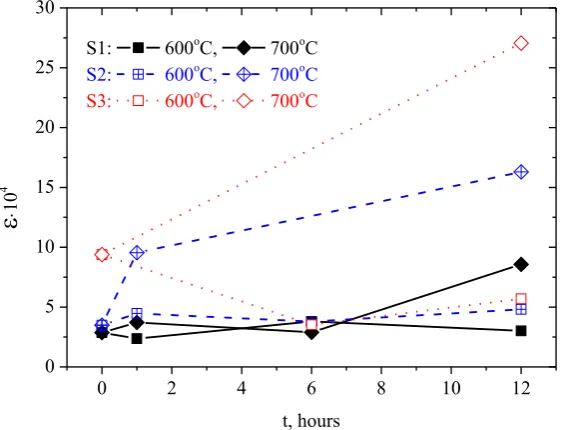
FIG. 4. The experimental values of the microstrain depending on the isothermal annealing duration. The value for the initial state is shown at t=0.
TABLE 1. LATTICE PARAMETER AND MICROSTRAIN FOR S1, S2 AND S3 STEELS QUENCHED AND AGED AT 600ºС AND 700ºС (1, 6, 12 HOURS)
Microstrain behavior depending on the isothermal annealing duration is shown in Fig. 4. It can be seen that after annealing at 600ºC microstrain is approximately constant or even slightly decreases. On the contrary, annealing at 700ºC leads to a significant increase in microstrain. Let us discuss the obtained results in more detail.
2.1. Investigation of oxide-dispersed-strengthened steels
2. FCC N26H5T3 alloy with 3 wt% Ti. For fcc alloy N26H5T3 with 3 wt% Ti after annealing at 600ºC Brinell hardness increases from 1360 to 1880 MPa, and microstrain remains at the level of 4.0·10-4 for all annealing durations. At the same time after annealing at 700ºC hardness increases from 1360 to 3160 MPa, and microstrain up to 18·10-4, i. e. four times. In the neutron diffraction pattern of this alloy the diffraction peaks of ´-Ni3Ti phase at both annealing temperatures are observed (Fig.5). However, after annealing at 600ºC (and 700ºC, 1 hour), they exhibit Lorentz type of broadening, which points to small particle size of this phase. These results are in good agreement with transmission electron microscopy (TEM) and electron diffraction [1] data – the ´-Ni3Ti phase particles were observed only after annealing at 700ºC, 6 and 7 hours. After annealing at 600ºC (and 700ºC, 1 hour) tweed contrast is clearly seen, which indicates a stress field change in the solid solution of the matrix due to the precipitation of the coherent ´-Ni3Ti phase nanoparticles.
FIG. 5. Precipitation kinetics of the -Ni3Ti phase (the additional peaks appearance in the patterns),
depending on the temperature and annealing duration of hardened alloy Н26Х5Т3 (alloy S2). Three strong diffraction peaks from matrix phase of the alloy are clearly visible at 2θ ≈ 42°, 49° and 73°, the low intensity peaks belong to the -Ni3Ti phase.
The similar behavior was observed during decay of the nitrous austenite [7]. Hardness increase at these heat treatment regimes we explain by the proximity of the studied steel to the Hadfield steel, in which martensitic transformation occurs easily during deformation, in our case, during the hardness test.
As a result of the destabilizing “high-temperature” (700-750ºC) aging, passing with the release of relatively large (up to 9-10 nm) incoherent vanadium carbide particles, austenitic matrix is depleted in carbon and vanadium. These results do not contradict the neutron structural data. At the “high-temperature” (700ºC) aging (Fig.3 and Table 1) due to the formation of the second phase – precipitation of relatively large (up to 9-10 nm) incoherent vanadium carbide particles – lattice parameter decreases from 3.60956 to 3.60050 Å, i. e. by 0.00906 Å, or in terms of 1 at% of carbon atom it is 0.0054 Å. This value is typical for lattice parameter changes during the dissolution of carbon in the fcc transition metals.
In accordance with popular opinion the microstress level around precipitation-hardening particles should decrease at the failure of coherence (due to the precipitation of the second phase). However, our measurements have shown that they remain at the level of microstrain produced by coherent vanadium carbides nanoparticles up to 30·10-4 for the 40H4G18F2 steel and slightly lower for coherent precipitates in the case of ´-Ni3Ti phase in N26H5T3 steel at 700ºC, 6 and 12 h (Fig.4). If we use the simplest approximation [6] for estimation of microstress values from measured microstrain σ = Е∙ε, where E - Young's modulus of steel, from our data follows that for the N26H5T3 alloy σ ≈ 300 MPa, and for the vanadium-carbide austenite σ ≈ 640 MPa, which is quite close to the yield point of these materials.
2.2. Н26Х5Т3 austenitic steel behavior under applied load
The experiments were performed on the MEREDIT neutron powder diffractometer in Nuclear Physics Institute of the Czech Academy of Sciences in Řež near Prague (http://neutron.ujf.cas.cz/meredit). The instrument is placed on the horizontal channel number 6 in the reactor hall of LWR15 light water reactor and it is mainly dedicated to the study of the crystalline and/or magnetic structure of the powder or polycrystalline samples. To enhance the possibility to measure the samples at different conditions there are several sample environments available for practical use: close cycle cryostat and vacuum furnace for temperature dependent studies in the range between 10 up to 1300 K, automatically exchangeable sample carousel for up to 6 samples, deformation rig with tensile/pressure load up to 20 kN for mechanical testing, an Euler goniometer for texture measurements available.
Three Н26Х5Т3 alloy samples were chosen for uniaxial loading, which were austenized beforehand at 1100°С during one hour and quenched in water. One sample was measured in quenched form, two other passed through preliminary thermal treatment at 600°С and 700°С for 12 hours to precipitate the strengthening Ni3Ti -phase.
2.1. Investigation of oxide-dispersed-strengthened steels
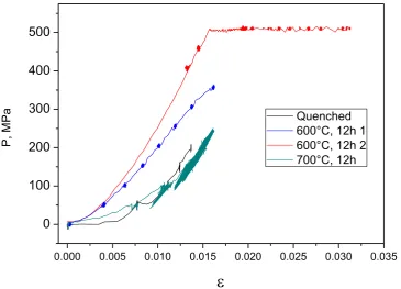
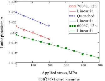
FIG. 6. Sample macro deformation as a function of uniaxial load at test temperature of 500°С: black line – quenched sample of Н26Х5Т3 alloy; green line – quenching + tempering at 700°С (12 h); blue line - quenching + tempering at 600°С (12 h, first cycle); red line - quenching + tempering at 600°С (12 h, second cycle).
Neutron diffraction patterns of all samples were measured in situ simultaneously with the sample macro deformation measurement. Lattice parameter dependence of the studied samples as a function of applied load is shown in Fig.7. As in case of mechanical deformation, micro deformation (Figs. 7, 8) exhibits greater rigidity for the sample annealed at 600°С. It was caused obviously by smaller precipitation of Ni3Ti -phase and this can be judged by the diffusion of diffraction peaks (see Fig.5).
0.000 0.005 0.010 0.015 0.020 0.025 0.030 0.035
0 100 200 300 400 500
P,
MP
a
FIG. 7. The fcc lattice parameters of Н26Х5Т3 alloy as a function of external load at various tempering after quenching: ○ – alloy after quenching, ▄ - quenching + tempering 600°С, 12 h, - quenching + tempering 700°С, 12 h.
FIG. 8. Microstrain in Н26Х5Т3 alloy as a function of applied load at various tempering after quenching (legend is the same as for the previous figure).
2.1. Investigation of oxide-dispersed-strengthened steels
FIG. 9. Effective modulus of elasticity based on neutron diffraction pattern data of Н26Х5Т3 alloy at 500°С (legend is given in Fig.7).
FIG. 10. Microstrain in Н26Х5Т3 alloy as a function of applied load at 600°С for various (hkl). Additionally, the fcc-lattice parameter dependence obtained by Rietveld method is shown.
FIG. 11. Diffraction line width of Н26Х5Т3 alloy as a function of applied stress at various tempering after quenching (legend is given in Fig.7).
FIG. 12. Microstrain (left) and calculated dislocation density values (right) of Н26Х5Т3 alloy as a
0 100 200 300 400 500
0.4 0.42 0.44 0.46 0.48
700°C, 12h Quenched 600°C, 12h
Peak width (°) vs. applied stress
Stress, MPa
Pe
ak
w
id
th
2.1. Investigation of oxide-dispersed-strengthened steels
2.3. Investigation of new heat-resistant ferrite-martensite steels 10H9K3V2MFBR and 10H9MFB by neutron diffraction and SANS
Heat-resistant pipeline components (elements of steam and boiler superheaters, turbines, blades, etc.) of thermal power plants operating in the creep range at temperatures up to 650°C are often made from tempered ferrite-martensite steels with approx. 10 %wt chromium content. Therefore, it is important to improve their thermal efficiency and mechanical properties. The heat treatment of tempered ferrite-martensite steels usually consists of two stages: austenization and tempering. It is well known that chromium in steels delays the formation of carbides, and that martensite phase forms in such steels after slow air cooling [10]. Ferrite-martensite steels have a complex microstructure which consists of fine micro grains separated by different kinds of interfaces (austenite grain boundaries, block boundaries and twin boundaries) and carbides which are precipitated near these boundaries. Additionally, these steels exhibit a very high dislocation density after heat treatment [11, 12]. Dislocations are produced in the parent phase during the martensitic transformation due to the associated martensite shear. As it well known from literature the dislocation density strongly drops in the early stages of tempering and then gradually further decreases with further aging. Ferrite-martensite steels with high dislocation densities exhibit specific mechanical properties. Thus they show cyclic softening when exposed to strain controlled fatigue testing and a strong decrease of creep rate during primary creep. The decrease of the high dislocation density in such material during tempering and creep accounts for the formation of subgrain boundaries that represent a dominant feature of ferrite-martensite steel microstructures.
Therefore new ferrite-martensite steels are of great interest for nuclear industry due to their unique heat- and radiation-resistant properties. To this end two newly developed in Russia heat-resistant ferrite-martensite steels 10H9K3V2MFBR and 10H9MFB (similar to P91 steel, Russ. grading) were investigated on FSD diffractometer at the IBR-2 pulsed reactor in wide range of tempering temperatures. These steels revealed good results in the long-term heat resistance which is by about 10% as compared with the previously developed steels of this type. This gives hope for its use in thermal power units at supercritical conditions (P = 30 MPa and T = 620°C). Hereinafter 10H9K3V2MFBR and 10H9MFB steels are designated as K3 and P91, accordingly.
Using TOF neutron diffraction it is possible to estimate in situ microstrain and coherent domain size in material from diffraction peak broadening and their changes with temperature and external load. Both mentioned phenomena are closely related to the dislocation structure inside the grain of polycrystalline materials. The obtained information will be useful for better understanding of the heat-resistant properties of investigated steels, as well as high embrittlement at low and high temperatures. This approach will give a possibility to optimize thermomechanical treatment of the steels to improve their properties.
FIG. 13. Left: Studied K3 steel sample inside the mirror furnace (1 kW, ~ 1000 C) during experiment. Right: Typical neutron diffraction spectrum from K3 ferrite-martensite steel sample heated at 200 °C.
Two series of experiments were performed on FSD diffractometer at the IBR-2 reactor. In first measurement initially quenched K3 steel sample was heated in situ in the mirror furnace from room temperature to 600ºC and at the same time the neutron diffraction spectra were recorded (Fig.13 and Fig.14). All the main diffraction peaks are indicated within the body-centered cubic group Im3m with lattice parameter a0 ≈ 2.87 Å. The diffraction data has been processed routinely by the Rietveld method in order to evaluate main crystal structure parameters changes with temperature (Fig.15). The lattice parameter dependence vs. temperature allowed estimating the linear thermal expansion coefficient of the material, which has a value typical for this class of steels α = (10.9±0.5)∙10−6 °C-1 (Fig.15, left). The neutron spectra measured on FSD diffractometer have shown significant diffraction peak broadening in comparison with reference sample (Fig.15).
In order to analyze peak broadening effects due to the crystal lattice microstrain and finite size of coherently scattering crystallites the individual diffraction peaks were fitted. Detailed analysis of peak widths revealed anisotropic character of peak broadening at which some reflection deviate from linearity (especially for (200) and (310) peaks). This deviation is usually associated with the dislocation contrast factor variation, repeatedly has been observed previously in the literature as well as in our earlier neutron experiments. The observed anisotropic peak broadening effect is expressed quite strongly and can be readily registered due to quite good instrument resolution of FSD. For correct microstrain evaluation this peak width anisotropy should be taken into account during fitting procedure which can be done using the model proposed in [13] (Fig. 17 and 18, left). The dislocation density behavior during heat treatment for both studied steels is presented in Fig. 18, right. It can be clearly seen that main changes occur in the temperature interval from 500°C to 600°C where sharp decrease of dislocation density is observed.
In addition, outlined above neutron diffraction measurements heat-resistant 10H9MFB (P91) steel samples were investigated at the SANS instrument “Yellow Submarine” in the Budapest Neutron Center, Hungary (Fig.19). Heat-treated steel plates of thickness of 1.8 mm were measured by SANS with the position of the PSD detector at 1 m (λ = 6 Å) and 6 m (λ = 6 Å and 12 Å). In the same positions a standard sample of the water and the background of fast neutrons were measured. The measurements were performed with magnetic saturation field of H = 1.4 T perpendicular to the scattering vector and without the field. The intensity of the SANS was analyzed by standard method with separation of nuclear and magnetic contributions (Fig.20). The nuclear SANS data were fitted using approach [14] in order to evaluate main structural parameters of the studied systems (Fig.22).
2.1. In
ve
stigat
ion
of ox
id
e-d
isp
erse
d-str
en
gt
he
ne
d ste
els
2.1. In
ve
stigat
ion
of ox
id
e-d
isp
erse
d-str
en
gt
he
ne
d ste
els
FIG. 16. Comparison of squared peak width (Δd)2 vs. squared interplanar spacing (d
hkl) 2 dependences (left) and the resolution function (right) for standard
FIG. 17. Fitting of anisotropic peak broadening: comparison of squared peak width (Δd)2 dependence vs. (A+B∙Γ
hkl)·d2 (left) and squared interplanar spacing
2.1. In
ve
stigat
ion
of ox
id
e-d
isp
erse
d-str
en
gt
he
ne
d ste
els
According to the nuclear SANS data the nature of neutron scattering changes from surface fractals to the volume fractals, which also indicates the mass appearance of carbonitrides, packages and other surfaces, which probably suppress the scattering from surfaces. It should be noted that after the mass precipitation of carbonitrides from martensite lattice and their coarsening, the scattering spectrum from these objects is shifted to the low Q region, which is not reachable at the “Yellow Submarine” spectrometer. However, at the same time the scattering by surface fractals is restored again.
3. CONCLUSIONS
The behavior of the hardness and lattice parameter of the fcc H16N15M3T1 steel after tempering does not provide valuable information about changing of materials structure. At the same time our analysis indicates an increase in the lattice microstrain after annealing at 700ºC, 12 h, caused most likely by formation of Ni3Ti type clusters. At the increase of the titanium concentration in the N26H5T3 alloy up to 3 wt% the early precipitation and precipitation stages of the second phase are observed. Joint diffraction and TEM analysis indicate that -Ni3Ti phase is formed after annealing 700ºC and the heat treatment duration of about 6 hours. During the growth of number of the precipitated particles at 600ºC microstrain does not increase, while the hardness increases. In addition, we see that with the growth of intermetallic nanoparticles, coherently coupled with the crystal lattice, the level of hardness and microstrain increases.
Unlike the previous steel, where the lattice parameters for the dispersion-hardening phase and for the matrix are almost equal, the lattice parameter of vanadium carbide nanoparticles is by 15.5% higher than in the matrix for the 40H4G18F2 steel. However, even in this case, at the failure of coherence caused by the second phase appearance there is a significant increase in microstrain, and not decrease, as is sometimes stated in the literature [15].
The dislocation density value obtained in our experiment with Н26Х5Т3 alloy (Fig.12) is comparable with dislocation density in ferrite-martensite steels. However, in our case the dislocation density drops sharply at prolonged high temperature creep tests. This fact as well as a sharp drop of Young’s modulus at increased temperature obviously complicates the use of this steel at high temperatures.
Sample Nr. 1 2: Tempering: 500°C, 1 h 3: 500°C, 100 h 4: 600°C, 1 h (initial) quenching at 1050°C
5: Tempering: 525°C, 3 h 6: 640°C, 5 h 7: 600°C, 24 h 8: 750°C, 3 h
ACKNOWLEDGEMENTS
This work was supported by IAEA research contract Nr. 16000. The authors are grateful to Dr. D. Sheptyakov, Dr. P. Lukáš, Dr. P. Mikula, Dr. P. Beran and Dr. Gy. Török for their assistance in conducting experiments and useful discussions.
COOPERATION WITHIN THE CRP PARTNERS
1) Institute of Nuclear Materials, Zarechny, Russia (A. Kozlov). The main task of this collaboration was investigation of residual microstresses in the radiation-resistant steels with BCC and FCC lattices which are used for reactor vessels, components of inter-reactor structures and fuel element shells during the process of formation, growth and coagulation of second-phase disperse particles. Microstress level was estimated in iron-based alloys with precipitates of coherent intermetallides Ni3Ti (type 16Cr-15Ni-3Mo-Ti and 36Ni-3Ti steels) and coherent carbides VC (type 15Cr-2Ni-Mo and 0.2C-18Mn-V steels).
2) Nuclear Physics Institute, Řež near Prague, Czech Republic (P. Mikula). Austenitic Н26Х5Т3 steel with -Ni3Ti precipitation-hardening phase behavior under applied load was studied on the MEREDIT neutron powder diffractometer in Nuclear Physics Institute of the Czech Academy of Sciences in Řež near Prague. The properties of quenched and tempered at various temperatures samples were compared: from measured strain-stress dependencies Young's moduli were estimated as well as microstrain and dislocation density values from diffraction line broadening as a function of applied stress.
4) Research Institute for Solid State Physics and Optics, Budapest, Hungary (Gy. Török). New ferritic-martensitic steels are of great interest for nuclear industry due to their unique heat- and radiation-resistant properties. To this end two newly developed in Russia heat-resistant martensitic steels 10H9K3V2MFBR and 10H9MFB (similar to P91 steel) were investigated at the SANS instrument in the Budapest Neutron Center. The SANS spectra measured on quenched and annealed samples exhibit a large surface fractal scattering in these steels. At the annealing temperature of 600ºC, 1 hour, an intensive precipitation of bulk fractal carbides and nitrides particles is observed. With further annealing carbides are enlarged in size and cannot be observed by SANS. This process restores the surface scattering on fractals up to high annealing temperature.
5) Institute of Nuclear Research, Pitesti, Romania (I. Ionita). The aging behavior of the Incoloy 800HT alloy and OL 304C austenitic stainless steel was studied at the Fourier Stress Diffractometer (FSD) in the Frank Laboratory of Neutron Physics of the JINR, Dubna, Russia. The samples were subjected to heat treatment for 60 days at 450ºC, 500ºC, 550ºC, 600ºC. Totally 10 samples in two series (Incoloy 800HT and OL 304C) were investigated. Both materials are going to be used in nuclear power industry due to their advanced properties. The 304-L alloy is an austenitic stainless steel with high ductility, good corrosion resistance, low yield stress and relatively high ultimate tensile strength. Incoloy 800 HT is a nickel based alloy with good mechanical properties and excellent corrosion resistance in water at high temperatures. For this reason Incoloy 800 HT alloy is exceptionally useful for many applications involving long term exposure to elevated temperature and corrosive atmosphere. Recently, this alloy starts to be studied as candidate material for fuel cladding in supercritical water reactors.
2.1. Investigation of oxide-dispersed-strengthened steels
FLNP JINR, Dubna. Zr-2.5 wt% Nb can be used as the pressure tube material for nuclear reactors due to its good mechanical strength, high corrosion and creep resistance. The final goal of these experiments is to estimate the macroscopic and intergranular residual stresses appearing after various technological processes; and optimize the annealing treatment required to relieve them to acceptable levels.
REFERENCES
[1] SAGARADZE, V., et al., The Physics of Metals and Metallography, 112 (2011) 543-551.
[2] FISCHER, P. et al., Physica B 276-278 (2000) 146.
[3] MITTEMEIJER, E.J., WELZEL U., Zeitschrift für Kristallographie 223 (2008) 552-560.
[4] HOLZWARTH U., GIBSON N., Nature Nanotechnology 6 (2011) 534. [5] RODRÍGUEZ-CARVAJAL, J., Physica B 192 (1993) 55-69.
[6] SAGARADZE, V., et al., The Physics of Metals and Metallography 111 (2011) 82-92. [7] BANNYH O.A. et al., Russian Metallurgy (Metally) 5 (2002) 55-59.
[8] H. CHOO, D.W. BROWN, “Intergranular Strain Evolution during High-Temperature Tensile Deformation”, SNS-HFIR User Meeting, Oak Ridge (2005).
[9] WILLIAMSON, G.K., SMALLMAN, R.E., III. Dislocation Densities in Some
Annealed and Cold-Worked Metals from Measurements on the X ray Debye-Scherrer Spectrum, Philosophy Magazine 1, 1 (1956) 34-46.
[10] KAYBYSHEV, R.O., et. al., New martensitic steels for fossil power plant: Creep resistance, The Physics of Metals and Metallography, 109, No. 2 (2010) 186-200. [11] PESICKA, J., et al., The evolution of dislocation density during heat treatment and
creep of tempered martensite ferritic steel, Acta Materialia 51 (2003) 4847-4862. [12] KIPELOVA, A.Yu., et al., Tempering-induced structural changes in steel
10KH9K3V1M1FBR and their effect on the mechanical properties. Metal Science and Heat Treatment, 52, 3-4 (2010) 100-110.
[13] UNGAR, T., et al., The contrast factors of dislocations in cubic crystals: the dislocation model of strain anisotropy in practice, J. Appl. Cryst. 32 (1999) 992-1002.
[14] HIRSCH, P.B., et al., Electron microscopy of thin crystals, Butterworths, London, 1968. [15] BEAUCAGE G., Small-angle scattering from polymeric mass fractals of arbitrary
mass-fractal dimension, J. Appl Cryst. 29 (1996) 134-149.
CRP related publications and presentations
1) G.D. BOKUCHAVA, A.M. BALAGUROV, V.V. SUMIN, I.V. PAPUSHKIN, “Neutron Fourier diffractometer FSD for residual stress studies in materials and industrial components”, Journal of Surface Investigation. X-ray, Synchrotron and Neutron Techniques, 4, 6, (2010) 879-890.
2) A.M. BALAGUROV, G.D. BOKUCHAVA, I.V. PAPUSHKIN, V.V. SUMIN, A.M. VENTER, “Neutron diffraction potentialities at the IBR-2 pulsed reactor for non-destructive testing of structural materials”, JINR Preprint E13-2010-84, Dubna, 2010. 3) V.V. SUMIN, G.D. BOKUCHAVA, I.V. PAPUSHKIN, A.M. BALAGUROV, A.M.
4) I.V. PAPUSHKIN, V.V. SUMIN, G.D. BOKUCHAVA, A.M. BALAGUROV, D.V. SHEPTYAKOV, “Determination of residual stresses in precipitation hardening steels by neutron diffraction”, STI-2011: The International Conference “Stress and Texture Investigations by Means of Neutron Diffraction”, http://sti2011.jinr.ru, Dubna (2011), JINR E14-2011-41 (2011) 49.
5) G.D. BOKUCHAVA, “Neutron Fourier diffractometer FSD for residual stress studies in advanced materials and industrial components”, in: The International Conference “Stress and Texture Investigations by Means of Neutron Diffraction 2011 (STI-2011)”, http://sti2011.jinr.ru, 6-9 June 2011, Dubna, Russia, Abstracts book, JINR E14-2011-41, 2011, 37.
6) G.D. BOKUCHAVA et al., “Anisotropic peak broadening studies on the RTOF diffractometer”, NSCMI-2012: XXII International Workshop on Neutron Scattering in Condensed Matter Investigations, Gatchina (2012).
7) I.V. PAPUSHKIN et al., “Microstrain in dispersion-hardened steels”, NSCMI-2012: XXII International Workshop on Neutron Scattering in Condensed Matter Investigations, Gatchina (2012).
8) V.V. SUMIN, “Investigation of the martensite decay in ferritic-martensitic steels by SANS method”, NSCMI-2012: XXII International Workshop on Neutron Scattering in Condensed Matter Investigations, Gatchina (2012).
9) G.D. BOKUCHAVA, V.V. Sumin, I.V. Papushkin, “Microstrain studies in ferrite-martensite steel using TOF neutron diffraction, FLNP Annual Report (2012).
2.1. Investigation of oxide-dispersed-strengthened steels
CHARACTERIZATION OF Y2O3 PARTICLE DISTRIBUTION IN OXIDE DISPERSION STRENGTHENED EUROFER STEEL FOR NUCLEAR
APPLICATIONS BY MEANS OF SMALL-ANGLE NEUTRON SCATTERING (SANS) AND OF NEUTRON DIFFRACTION
R. COPPOLA*, M. VALLI**
*ENEA-Casaccia, Via Anguillarese 301, 00123 Roma, Italy ** ENEA-Faenza, Via Ravegnana 186, 48018 Faenza (RA), Italy Email: [email protected]
Abstract.
This report summarizes the scientific results obtained in the frame IAEA Agreement No. 16200/R0 4/5/2010 until May 2013. Small-angle neutron scattering (SANS) and neutron diffraction measurements have been carried out on Oxide Dispersion Strengthened (ODS) Eurofer97 and 14 Cr ferritic/martensitic steels, obtaining relevant information on their microstructure. Collaborative results have also been obtained with other CRP participants, concerning the optimization of SANS data analysis, compared SANS measurements on ODS material at different neutron sources and the characterization of H-loaded Zr tubes.
1. INTRODUCTION
This report refers to the experimental activities carried out until May 2013 to characterize by means of small-angle neutron scattering (SANS) and neutron diffraction the microstructure of Oxide Dispersion Strengthened (ODS) Eurofer97 and 14 Cr ferritic/martensitic steels, based on the following originally proposed work plan:
Year 1
1.1 SANS measurements of polycrystalline and nano-structured Eurofer-ODS. 1.2 SANS data analysis.
Year 2
2.1 Neutron diffraction measurements of polycrystalline and nano-structured Eurofer-ODS. 2.2 Neutron diffraction data analysis.
Year 3
3.1 Correlation of neutron diffraction and SANS results.
3.2 Preparation of a technical report summarizing the obtained results and outlining their relevance to the metallurgical characterization and optimisation of the investigated material. The objectives of this work plan have up to now been mostly fulfilled (except 3.2), a considerable amount of SANS and neutron diffraction experimental data has been collected on different ODS ferritic/martensitic steels and data analysis has been carried out or is underway. However, a deep and complete metallurgical characterization of microstructural evolution in such complex materials will require collaborative efforts well beyond the deadline of this CRP, as it was also discussed during the 2nd RCM (Beijing, September 2011). More specifically, the results obtained by neutron techniques are being correlated with other microstructural information, obtained by other techniques and some scientific papers are in preparation or submitted for presentation at international conferences.
CNEA on H-loaded Zr tubes SANS characterization, obtaining quite recently very promising SANS results. Finally, this CRP has allowed strengthening the collaboration with JRC, already established in the frame of the “NeT – Network on Neutron Techniques Standardization for Structural Integrity”.
2. INDIVIDUAL PROGRESS REPORT ON THE WORK CARRIED OUT AND RESULTS OBTAINED
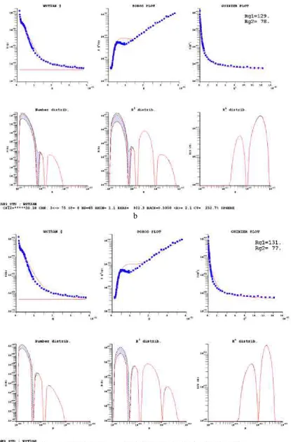
SANS measurements have been carried out on 14 Cr ODS Y2O3 0.35 wt% ferritic martensitic steel with Ti contents ranging from 0.2 wt% to 0.4 wt%, provided by KIT, where such promising laboratory heats are being produced and characterized, both mechanically and by TEM and ATP. A reference 14 Cr ODS sample, with no Ti, and three samples with respective Ti contents of 0.2, 0.3 and 0.4 wt% were investigated by SANS at the D22 instrument at the High Flux Reactor of the Institut Max von Laue – Paul Langevin (ILL) in Grenoble, France. Sample-to-detector distances of 2 m and 11 m were utilized with a neutron wavelength of 6 Å, giving an experimental range corresponding to particle sizes ranging between 10 and 300 Å in size approximately. A saturating magnetic field of 1 T was utilized to separately measure the nuclear and magnetic SANS components.
a b
FIG.1. Nuclear SANS cross-sections (cm-1 vs Å-1) of 14 Cr ODS Y
2O3 0.35 wt% ferritic / martensitic steel with different Ti contents (a) whole spectrum, b) 2 m
sample-to-detector distance.
a b c
FIG. 3. Number distribution functions (number of particles per unit volume with size between R and R+dR) for 14 Cr ODS without 0 (a) 0.3 (b) and 0.4 (c) wt% Ti; the uncertainty band is 15-20%.
FIG. 4. Nuclear SANS cross-sections (cm-1 vs Å-1) of nano-structured 9 Cr Eurofer ODS (empty dots) 14 Cr ODS Y
2O3 0.35 wt% (full dots) ferritic/martensitic
2.1. Investigation of oxide-dispersed-strengthened steels
The size distribution functions obtained by the method described in ref.s [4,5] for Ti contents varying between 0 and 0.4 wt% are presented in Fig. 3, showing the occurrence of the new phase when Ti is added.
This new 14 Cr ODS heat (Ti-free reference) has been compared to 9Cr Eurofer ODS material, also previously investigated by SANS: it is clear from Fig. 4 that increasing the Cr content results in a more heterogeneous microstructure.
3. COLLABORATIVE EFFORTS AND RESULTS ACHIEVED Joint work with other CRP participants has consisted in the following:
3.1. In collaboration with BNC-Budapest Dr. G. Torok
A series of SANS data obtained on an aged duplex steel has been analysed by the transformation method reported in ref.s [4,5] in order to contribute in assessing the reliability of the size distribution functions. The most interesting result is shown in Fig. 4, referring to the data obtained on samples showing inter-particle interference effects: even without introducing in the model the interference effect, increasing to 8-9 the number of B-spline reduces considerably the fitting problems; work is underway to eliminate the unphysical oscillations in the obtained distributions and to compare with the results obtained on the same samples by other methods.
b
c
2.1. Investigation of oxide-dispersed-strengthened steels 3.2. In collaboration with BNC, Dr. T. Gyula
A set of nano-structured 9 Cr Eurofer ODS, submitted to annealing at temperatures ranging between 750°C and 1150°C, [6] characterized by SANS at the ILL-Grenoble (Fig. 5) has been characterized at the at the BNC reactor. Figure 6 shows the good agreement of these two SANS measurements, carried out on the same ODS sample, at two different neutron sources. Experimental details on this “round robin” exercise will be provided in the report by Dr. T. Gyula.
FIG. 6. Nuclear SANS cross-sections (cm-1 vs Å-1) of Eurofer ODS mechanically alloyed
nano-powders annealed between 850°C and 1150°C (measurements carried out at the ILL-Grenoble).
0,1 1
Comparison of sample measured BNC and ILL HXN950 T=1150C H=1.4T nuclear
Int
FIG. 7. Comparison of SANS nuclear cross-sections of Eurofer-ODS mecanichally alloyed nano-powders submitted to 2 h annealing at 950° C measured at ILL (red ) and at BNC (blue). 3.3. SANS measurements
cross-section one order of magnitude higher with a completely different high Q background. Both samples exhibit marked anisotropy (relating to the tube texture) accentuated in the H-loaded material by the growth of elongated large hydride precipitates. Figure 9 shows the size distribution obtained from the difference between h-loaded and reference sample utilizing the B-spline method for polydisperse systems: clearly, to obtain a reliable fit the system anisotropy has to be taken into account. Work is underway, as well as to try and determine the H content from integrated SANS intensity and transmission measurements.
FIG. 8. Radially averaged SANS cross sections (cm-1 vs Å-1) of CNEA H-loaded and H-free Zr samples
(unpublished measurements carried out by Dr. Andre Heinemann, TUM).
2.1. Investigation of oxide-dispersed-strengthened steels
4. REMAINING WORK-PLAN
4.1. Individual work
As clarified in the introduction, completing the SANS and neutron diffraction data analysis of the investigated ODS materials, summarizing these findings in scientific publications.
FIG. 9. Best fit and size distributions for the difference between CNEA H-loaded and H-free samples obtained by the B-spline method of Ref. (4, 5).
4.2. Collaborative efforts
As a collaborative work, some completion of SANS data analysis of H-loaded Zr tubes with be done with the involved partners.
5. SUMMARY AND CONCLUSIONS
The activities foreseen by the agreed work plan are on schedule, they have allowed a considerable progress in the characterization of microstructural effect relating to compositional changes in ODS ferritic/martensitic steels; further progress is expected by metallurgical analysis based also on the results of other non-nuclear techniques. Additionally significant interactions have been established with other CRP participants, to be hopefully kept and further developed and in the future.
REFERENCES
[1] HE, P., KLIMENKOV, M., LINDAU, R., MOSLANG, A., J. of Nuclear Materials 428
(2012) 131
[2] RHOGOZKIN, A., et al., to be published.
strengthened steels of interest for fusion technology, pres. at ICFRM16 and J. N. Mat 455 (2014) 426-430.
[4] MAGNANI, M., PULITI, P., STEFANON, M., Nucl. Inst.& Meth. A271 (1988) 611. [5] COPPOLA, R., KAMPMANN, R., MAGNANI, M., STARON, P., Acta Mat. 46 (1998)
5447.
2. RESULTS ACHIEVED
2.2. RESEARCH ON ZIRCONIUM BASED
MATERIALS (INCLUDING HYDROGEN
NEUTRON SCATTERING ACTIVITY AT LOS ALAMOS NATIONAL LABORATORY
M.A.M. BOURKE
Los Alamos Neutron Science Center, MS H805, Los Alamos National Laboratory, Los Alamos, NM 87545, U.S.A.
Email: [email protected]
Abstract.
The nondestructive and bulk penetrating aspects of neutron scattering techniques make them well suited to the study of materials from the nuclear energy sector (particularly those which are radioactive). This report provides a summary of the facility, LANSCE, which is used at Los Alamos National laboratory for these studies. It also provides a brief description of activities related to line broadening studies of radiation damage and recent imaging and offers observations about the outlook for future activity. The work alluded to below was performed during the period of the CRP by researchers that included but were not limited to; Sven Vogel and Don Brown of Los Alamos National Laboratory; and Anton Tremsin of the University of California, Berkeley.
1. INTRODUCTION
Neutron scattering offers unique advantages for characterization of materials relevant to the nuclear energy sector. In contrast with electrons or (low) energy X rays, neutrons penetrate most materials to depths of several centimetres. This both allows measurements through cladding and allows concomitant use of shielding to mitigate radiation dose. Since neutron interactions with nuclei do not scale with atomic number and are isotope specific they are flexible and prove to be equally pertinent for the study of hydrogen and uranium. Although samples typically need to be larger than a cubic millimeter nevertheless a range of microstructural length scale insights are possible. To place work described below into a wider context the reader is directed to a review of neutron scattering applied to nuclear materials by Vogel [1].
Los Alamos national laboratory in collaboration with national and international partners is engaged in a range of applied and fundamental studies of radiation damage. Much of the work is applied and initiated both by the U.S. Office of nuclear energy but there is considerable complementary funding on fundamental research. The range of activities span ceramic fuels, accident tolerant cladding to metallic fuels and the use of supercomputers to connect first principles insights to engineering relevance. Industrial activity has included examination of 100 Kg structural welds that were removed from nuclear reactors. LANL routinely machines and prepares radioactive samples for electron microscopy. Hot cells are used to examine highly radioactive material removed from reactors. Thermophysical properties and fabrication processes for urania based fuels are examined in The Fuels Research Laboratory. An Ion Beam Materials Laboratory enables simultaneous ion irradiation of surfaces in contact with molten metals to assess synergistic effects of irradiation on corrosion. A strong theoretical and simulation computational mechanics effort spans the atomistic to macroscopic regime. It is in this context that neutron scattering measurements at the LANSCE facility are employed.
2. LANSCE FACILITY
2.2. Research on zirconium based materials (including hydrogen uptake)
short proton pulse width. The former offers a broad bandwidth that is well suited to studies of soft condensed matter and pair distribution function analysis. The latter enables resonance imaging using epithermal neutrons for which the pulse width of the incident proton beam is critical. The Lujan Center also supports the Department of Energy’s national security mission and performs programmatic and classified research in support of LANL programs.
Provided belowis a brief description of activity at LANL pursued within the context of the CRP addressing studies of irradiated material and proof of principle studies of irradiated material.
At the Lujan Center several instruments have been used extensively for studies of nuclear energy related materials. HIPPO provides time-resolved studies under a variety of extreme temperature, magnetic field, and pressure conditions. NPDF provides local structure studies for amorphous, disordered, and nano materials, as well as routine high-resolution powder diffraction. SMARTS is optimized for engineering and provides in situ deformation, with a unique loading capability of 250 kN in conjunction with temperature from 77 K to 1800 K. Both SMARTS and HIPPO offer complementary capabilities focused on extreme conditions (temperature, stress, magnetic field and pressure), determining crystal structure, texture, and lattice strains. HIPPO provides in situ texture measurements at temperatures from 10 K to 2000 K, as well as at pressures to 10 GPa. Many material characteristics derive from surface and interface properties in which interactions on the atomistic, molecular, and nano scales determine higher-order morphology and properties. In work that preceded this CRP, Brown et al. utilized the engineering diffractometer SMARTS [2] to investigate the uni-axial deformation behavior of uranium at room temperature as well as 200°C and 400°C [66].
3. RESULTS
3.1. Results: diffraction studies of radiation damage
Zirconium and its alloys are used in nuclear applications due to its compromise between mechanical performance under high pressure/high temperature condition and its neutronic transparency. Thus its behavior during manufacturing, in service and under accident scenarios is a topic of interest. Pure zirconium has a hexagonal closed packed (hcp) crystal-structure up to 866°C and transforms to a body-centered cubic (bcc) crystal structure above that. For nuclear applications the main alloying elements are niobium and tin which with with other minor elements form the Zircaloy 2 alloy. Neutron diffraction has been applied to zirconium and its alloys to characterize welds, characterize deformation modes to allow predictive modeling of deformation, investigate the development of texture under temperature and stress, and characterize the phase transformations including texture variant selection during the hcp/bcc phase transformation.
non-Ferritic/martensitic steels such as T91 (9Cr1Mo) and HT-9 (12Cr1Mo) have also been used for nuclear fuel cladding. In similar work to that of the Zirconium study Hosemann et al. studied the evolution of the microstructure, i.e. phase composition, texture etc. in situ using neutron diffraction [6]. Deformation behavior was investigated by Clausen et al. [7] using in situ neutron diffraction and modeled using elasto-plastic self-consistent (EPSC) modeling. These experiments on (non-irradiated specimens) provide baseline data for future experiments on irradiated materials. Comparing the mechanical response of irradiated and non-irradiated materials will allow to understand the influence of radiation damage on the mechanical behavior of these materials and provide benchmark data for advanced deformation models that attempt to include radiation damage [8]. In complementary work Anderoglu et al. studied the microstructure and phase evolution in a fully tempered ferritic /martensitic HT-9 steel irradiated in the Fast Flux Test Reactor Facility (FFTF) up to 155 dpa at a temperature range of 380 to 504 °C [9] using small angle neutron scattering using the LQD instrument.
3.2. Results: proof of principle, imaging of ceramic fuels
Neutron radiography and tomography are based on the attenuation of neutron beams by the sample. Since the interaction of neutrons with matter is fundamentally different from X rays, they allow investigations that are qualitatively different. A good example is the observation of hydrogen in operating systems. Recent detector developments have allowed for spatially and time-resolved neutron detection [10] and are opening new avenues of research. Specifically the characterization of nuclear materials and nuclear fuels with isotope-sensitive imaging via neutron resonance absorption imaging [11]. A program exploring advanced non-destructive examination (NDE) capabilities using neutron and proton imaging was initiated in 2011 between Los Alamos National Laboratory and Idaho National Laboratory.
To illustrate the advantages of neutron radiography and energy-dispersive neutron radiography mock nuclear fuel rodlets were prepared using urania powder. Each consisted of five pellets and were characterized by high energy proton radiography, X ray radiography [12], energy-dispersive neutron radiography, and thermal neutron radiography [13]. To simulate cracks and voids that typically result during irradiation and burn-up, plastic wire was introduced during synthesis and which burned out during sintering leaving a range of defect features. As a proof of principle to assess the viability of the resonance technique to detecting the different fission products (that would typically form during the life cycle of a nuclear fuel) tungsten pieces of different sizes and shapes were embedded. Finally, some fuel pins were sintered with different green (pre-sintering) densities.
2.2. Research on zirconium based materials (including hydrogen uptake)
4. SUMMARY
Determination of the positions of light elements in the presence of heavier ones is an area of competitive advantage for neutron scattering techniques. For example the complex crystallography of urania can accommodate a large range of hyper-stoichiometric oxygen atoms and will continue to offer a rich field of research for neutron diffraction. While stoichiometric UO2 crystallizes in the CaF2 structure, concentrations up to UO2:25 are possible at elevated temperatures with the location of the excess oxygen atoms affecting lattice dynamics and therefore thermal expansion and thermal conductivity. At lower temperatures, several distinct crystallographic phases occur in the U-O phase diagram, many of which were determined and refined by neutron diffraction.
Imaging is now an integral part of the instrument suite at many neutron sources. In particular energy-dispersive neutron imaging, enabled by new detector technology, offers interesting opportunities. Further improvements in detector efficiency, for example through doping the neutron converters with specific isotopes, will further improve the potential of this technique. In the realm of data analysis further advances may also be expected. For example, when tomographic reconstruction software (that is routinely applied in medical applications) is applied to energy-dispersive neutron data. With improved sensitivity, accurate measurements of isotope concentrations will be possible, which will allow new opportunities for the study of ion migration.
Modeling of reactors depends on the precise knowledge of interaction cross-sections of thermal neutrons with reactor materials. These cross-sections are energy-dependent and in the thermal neutron energy range are convoluted with coherent and incoherent inelastic and elastic scattering properties as well as with resonant absorption. Intense pulsed spallation neutron sources offer rapid cross-section measurements in the thermal energy region for reactor materials.
The benefits of neutron diffraction for crystallographic studies of fuels, consisting of high and low Z-number elements, are obvious. Development of new fuels or advanced sample environments to study these materials at extreme conditions, will continue. Few high temperature and controlled atmosphere experiments above 1500°C are reported. Thus advances in sample environments at neutron sources offer potential return on investment. Combinations of diffraction with the recently developed spatially resolved neutron time-of-flight detectors for energy-dispersive neutron radiography will open up entirely new avenues of neutron scattering research.
REFERENCES
[1] Vogel, S. “A review of neutron scattering applications to nuclear materials” in press. [2] M. Bourke, D. Dunand, E. Ustundag, SMARTS-a spectrometer for strain measurement
in engineering materials, Applied Physics A: Materials Science & Processing 74 (2002) 1707–1709.
[3] D. Brown, M. Bourke, B. Clausen, D. Korzekwa, R. Korzekwa, R. McCabe, T. Sisneros, D. Teter, Temperature and direction dependence of internal strain and texture evolution during deformation of uranium, Materials Science and Engineering: A 512
(2009) 67–75.
[4] G. Rib´arik, J. Gubicza, T. Ung´ar, Correlation between strength and microstructure of ball-milled al–mg alloys determined by X ray di ffraction, Materials Science and Engineering: A 387 (2004) 343–347.
[5] L. Balogh, D. W. Brown, P. Mosbrucker, F. Long, M. R. Daymond, Dislocation structure evolution induced by irradiation and plastic deformation in the zr–2.5 nb nuclear structural material determined by neutron diffraction line profile analysis, Acta Materialia 60 (2012) 5567–5577.
[6] P. Hosemann, S. Kabra, E. Stergar, M. Cappillo, S. Maloy, Micro-structural characterization of laboratory heats of the Ferric/Martensitic steels HT-9 and T91, Journal of Nuclear Materials 403 (2010) 7–14.
[7] B. Clausen, D. Brown, M. Bourke, T. Saleh, S. Maloy, In situ neutron diffraction and elastic–plastic self-consistent polycrystal modeling of HT-9, Journal of Nuclear Materials 425 (2012) 228–232.
[8] N. R. Barton, A. Arsenlis, J. Marian, A polycrystal plasticity model of strain localization in irradiated iron, Journal of the Mechanics and Physics of Solids (2012). [9] O. Anderoglu, J. Van den Bosch, P. Hosemann, E. Stergar, B. Sencer, D.
Bhattacharyya, R. Dickerson, P. Dickerson, M. Hartl, S. Maloy, Phase stability of an HT-9 duct irradiated in FFTF, Journal of Nuclear Materials (2012).
2.2. Research on zirconium based materials (including hydrogen uptake)
IN-SITU NEUTRON RADIOGRAPHY INVESTIGATIONS OF THE HYDROGEN RE-DISTRIBUTION DURING DHC
M. GROSSE*, C. RÖSSGER*, S.VALENCE**, J.BERTSCH**,A. KAESTNER**, J. SANTISTEBAN***
* Karlsruhe Institute of Technology, Institute for Applied Materials, PO Box 5640
D-76021 Karlsruhe, Germany
**Paul Scherrer Institute Villigen, CH-5232 Villigen PSI, Switzerland ***Comision Nacional de Energia Atomica, Bariloche, Argentina
Email: [email protected]
Abstract.
The hydrogen uptake and re-distribution in mechanical pre-loaded Zircaloy-4 specimens were investigated by means of in-situ neutron imaging. The stress fields in the material affect the hydrogen uptake as well as its distribution in the material. The investigations confirmed the existence of an initial oxide layer formed at room temperature by contact with air. This oxide layer suppresses the hydrogen uptake until dissolution in the zirconium matrix.
1. INTRODUCTION
Corrosion of nuclear fuel claddings made from various zirconium alloys in water or steam results in a production of free hydrogen:
Zr + 2 H2O↔ZrO2 + 4 H (1) Partial strong local concentrations results in a degradation of the mechanical properties which may induce mechanical failure of the nuclear fuel cladding tubes at low loadings. The hydrogen absorption based reduction of strength and toughness is of high safety relevance for the reactor under service and transient conditions.
One of these failure modes, the delayed hydrides cracking (DHC), is characterized by crack propagation at macroscopic sub-critical load. It takes advantage of the interplay between stress concentrations at a stress raiser and hydrogen precipitation when the local content reaches the terminal solid solubility limit. The hydrogen diffuses in the strained region of the stress field in front the tip of a crack. It reduces the strength and toughness of this area significantly. The crack can grow in this area. The stress field shifts ahead the newly formed crack tip and the hydrogen follows. The diffusion characteristics of hydrogen in Zircaloy-4 under temperature and concentration gradients are well known [1]. Otherwise, the effect of the stress gradient is still an open issue [2]. The main blocking point pertains to the difficulty to make in-situ measurement of hydrogen content under viable testing conditions, e.g. temperature above 400 K under mechanical loading. Post-mortem investigations do not allow distinguishing between hydrogen diffusion effectively driven by the stress gradient at test temperature and by the decrease of the solubility during cooling down to room temperature. Moreover, postmortem investigations do not allow characterizing the kinetics of the hydrogen diffusion.
2. EXPERIMENTS
The neutron imaging investigations were performed at the ICON facility at the Swiss neutron source SINQ (Paul Scherrer Institute Villigen, Switzerland). The non-destructive character of neutron imaging allows in-situ investigations of hydrogen uptake and relocation in zirconium alloys. The strong contrast between hydrogen (very high total neutron cross section) and zirconium (very low total neutron cross section) provides the possibility to detect even small changes in the hydrogen concentrations.
For in-situ neutron radiography investigations, the INRRO (in-situ neutron radiography reaction oven) was constructed. Figure 1 shows a scheme of the furnace. It is a resistivity heated horizontal tube furnace with two windows transparent for neutrons on the front and back side. The furnace allows studying chemical reactions in a well defined flowing gas atmosphere at temperatures up to 1750 K.
The measurements were performed applying the middle imaging setup and a collimation ratio L/d of about 340. An acquisition time of 117 s results in a frame repetition time of 2 min. The spatial resolution was about 0.1 mm. For the mechanical loading during the annealing in the INRRO furnace a special sample load device was constructed.
The experiments comprise annealing at 350°C in argon/hydrogen atmosphere for hydrogen loading of the samples until complete destruction. In a second beam time, hydrogen was loaded up to a certain local hydrogen concentration followed by an annealing in inert atmosphere at the same temperature. The field of view was limited by the INRRO furnace windows with a diameter of 40 mm.
2.2. Research on zirconium based materials (including hydrogen uptake)
3. RESULTS
The investigations of the hydrogen uptake and redistribution in mechanical pre-stressed specimens were performed in two beam-times. At first, pre-stressed specimens were annealed at 350°C in Ar/H2 atmosphere. A radiograph sequence of this experiment is given in Fig.2.
No hydrogen uptake occurred during the first 8 h. The reason may be that an initial sub-micrometer thick oxide layer formed at room temperature during manufacturing, preparation and material storage. This initial oxide layer has to be dissolved to enable hydrogen uptake. After this time, the hydrogen absorption starts at the notch position. The data do not allow deciding why the uptake starts here, if due to the stress field or to the manufacturing of the specimen. After about 10 h the hydrogen is concentrated in the specimen region with the highest tensile stress (clearly visible as darker regions e.g. in the frames taken at 37080 and 39700 s). Spallation of small hydrides from the sample starts at the same time (dark objects below the specimen).
Later, hot spots of the hydrogen uptake are formed. These dark hot spots characterized by very high hydrogen concentrations grow and result in additional breakaway of small hydrides from the sample until the specimen is completely destroyed and the mechanical stress is relieved after about 15 h.
In a second beam-time the experiment was varied. The pre-oxidation and removing of the oxide layer at both sides of the notch defined the position of the hydrogen uptake. The samples were annealed again in Ar/H2 atmosphere at 350°C. In order to prevent the complete destruction of the sample, the hydrogen supply was switched off after reaching a certain gray value in the radiograph at 17000 s. Figure 3 shows a radiograph sequence of the notch and pre-crack sample region taken during the hydrogen loading phase and at the end of the experiment is given. The time needed for dissolving the initial oxide produced between the removing of the pre-oxidation at both sides of the notch and starting the annealing (several minutes) was about 4.5 h. A fast hydrogen uptake follows.
FIG. 2. Neutron radiograph sequence taken during the destruction of a mechanical stressed specimen in Ar/H2 atmosphere at 350°C.
14000 s 15000 s 16000 s 17000 s 18000 s 57000 s
FIG. 3. Neutron radiograph sequence taken during hydrogen loading in Ar/H2 atmosphere until 18000 s and inert annealing of a mechanical stressed specimen
until 57000 s at 350°C.