A STUDY OF THE INFLUENCE OF GUIDE VANE DESIGN ON SAVONIUS WIND TURBINE PERFORMANCE
Thesis
Organized to fulfill the requirement to achieve Postgraduate degree of Mechanical Engineering
ELSADIC SALIM .A. MOHAMED NIM. S951208505
POSTGRADUATE PROGRAM SEBELAS MARET UNIVERSITY
SURAKARTA 2015
ii
iii
iv
ORIGINALITY AND PUBLICATION STATEMENT
The writer declared that:
1. Thesis entitled: “A STUDY OF THE INFLUENCE OF GUIDE VANE DESIGN ON SAVONIUS WIND TURBINE PERFORMANCE“ is an original work of the writer without plagiarism, and there is no scientific papers that have been asked by others to obtain academic degrees and there is no work or opinion ever written or published by another person without mentions as reference on the text and a reference source as well as mentioned in the bibliography. If there is a proven plagiarism towards scientific papers in future, the writer accepts sanctions as consequence in accordance with provisions of the legislation (Permendiknas No 17, tahun 2010).
2. Publication of a part or entire thesis content in scientific forums was permitted and must be included author and supervisors as a team. If there is no publishing of a part or entire thesis contents at least within a semester (six months after final examination), Mechanical Engineering Program of UNS has a right to publish in scientific journal publisher. When the writer contravene this publication, the wrier is willing to get an academic sanction.
v
ELSADIC SALIM .A. MOHAMED, Student Number: S951208505 A STUDY OF THE INFLUENC OF GUIDE VANE DESIGN ON SAVONIUS WIND TURBINE
PERFORMANCE. Supervisor I: Dr. Danardono Dwi Prija T, ST, MT, Ph.D. Supervisor II: Dr. Dwi Aries Himawanti, ST, MT. Thesis: Mechanical Engineering Department, Graduate School of Sebelas Maret University.
ABSTRACT
This work experimentally studied the influence of guide vane design to increase Savonius rotor performance. Guide vane is one of additional device that its function is to direct wind stream onto concave blade and deserves as obstacle of the wind that flowing on to convex blade. This method increased wind speeds to the rotor, consequently it produced higher power and the Savonius rotor performed better. Four designs of guide vane were arranged in this study. They were basic design of guide vane and basic design of guide vane that added a tilt angle on the top and bottom sides by 15°, 30°, and 45°. The result concluded that guide vane affects the performance of Savonius rotor. The power that generated by the rotor with guide vane increases significantly compared with Savonius rotor without guide vane. The maximum improvement was attained up to 65.89%.
Keywords: Wind energy, Wind Turbine, Savonius rotor, Guide Vane, Savonius rotor performance
vi
CONTENT LIST
COVER ... i
APPROVAL PAGE ... ii
ORIGINALITY AND PUBLICATION STATEMENT ... iii
ABSTRACT ... v
CHAPTER II LITERATURE REVIEW AND BASIC THEORY ... 4
2.1.Literature Review ... 4
2.2.7. Method to Improve Savonius Wind Turbine Performance ... 12
2.2.8. Principle of Wind Energy Conversion ... 15
2.2.9. Betz‟s Momentum Theory ... 15
2.2.10.Power Coefficient and Tip Speed Ratio... 18
2.2.11.Torque ... 20
CHAPTER IIIRESEARCH METHODOLOGY ... 21
3.1. Research Place ... 21
3.2. Apparatus ... 21
vii
3.4. Step of Research Diagram ... 25
CHAPTER IV RESULT AND DISCUSSION ... 27
4.1. Result of Experiment ... 27
4.2. Discussion ... 28
CHAPTER V CONCLUSION ... 33
REFERENCE ... 34
APPENDIX ... 36
viii FIGURE LIST
Figure 2.1 Aerodynamic Force of Wind Turbine ... 8
Figure 2.2 Horizontal Axis Wind Turbine ... 8
Figure 2.3 Vertical Axis Wind Turbine of Darrieus ... 9
Figure 2.4 Savonius Wind Turbine Model ... 11
Figure 2.5 Principle of Savonius Rotor ... 11
Figure 2.6 Deflector Plate ... 12
Figure 2.7 Double-step Savonius Wind Turbine ... 12
Figure 2.8 Twisted-Savonius Wind Turbine ... 13
Figure 2.9 Modification of Savonius Wind Turbine Parameters ... 14
Figure 2.10 Savonius Wind Turbine with Guide Vane ... 15
Figure 2.11 Flow condition due to the extraction of mechanical energy from free-stream air flow according to the elementary momentum theory ... 16
Figure 2.12 Power coefficient compared to the flow velocity ratio of the flow before and after the energy converter ... 18
Figure 2.13 Characteristic of Power Coefficient and Tip Speed Ratio for some wind turbines... 19
Figure 2.14 Characteristic of Torque Coefficient and Tip Speed Ratio for some wind turbines... 20
Figure 3.1 Model of VerticalAxisWind Turbine Savonius ... 21
Figure 3.2 Savonius Wind Turbines with Guide Vane Model ... 22
Figure 3.3 Models of Guide Vane Various Designs ... 22
Figure 3.4 Experiment set-up ... 23
Figure 3.5 Steps of Research Diagram ... 25
Figure 4.1 Frequency and Velocity ... 27
Figure 4.2 Correlation between RPM and velocity ... 27
Figure 4.3 Correlation between Power Coefficient and Velocity ... 28
Figure 4.4 Correlation between Power Coefficient and Tip Speed Ratio 29 Figure 4.5 Correlation between Torque Coefficient and Velocity ... 30 Figure 4.6 Correlation between Torque Coefficient and Tip Speed Ratio 30
ix TABLE LIST
Table 2.1 Resume of Previous Study ... 6 Table 4.1 Table of Frequency and Wind Speed ... 27 Table 4.2 Data Experiment of RPM ... 27 Table 4.3 Comparison of Maximum Power Coefficient and
Maximum Tip Speed Ratio with previous study ... 31
x
NOMENCLATURE
E Kinetic Energy .
m Mass flow (kg/s) Velocity (m/s) ρ Density (kg/m3) A Swept Area (m2) P Power (Watt) Po Wind Power (Watt) Cp Power Coefficient ω Angular Speed (1/s)
R Tip radius of Savonius Wind Turbine (m) λ Tip Speed Ratio
N Rotational speed of Rotor (rpm) D Diameter (m)
T Torque (Nm) Ct Torque Coefficient
1 CHAPTER I INTRODUCTION
1.1. Background of the Study
Renewable energy of wind interest increases as alternative energy to fulfill the increasing of energy needs over the world. It is being important due to decrease of fossil fuel resources. Moreover, the fossil fuels cause environment pollution. CO2 emission of the fossil fuels brings greenhouse effect and global warming. Utilization of wind energy is reliable to reduce the usage of fossil fuels(Alam, Ali et al. 2012). It means reducing environmental problems. Wind power is transformation of wind energy into electricity by using wind turbine. The wind energy is basically the kinetic energy of large masses of air moving over the surface of earth. The wind turbine receives the kinetic energy, then transforms it into electrical forms (Mathew 2006).
Vertical-axis wind turbines (VAWTs) have been tested to be effective devices to extract energy from the wind. VWATs have been used to generated mechanical and electrical energy at a range of scales, from small-scale applications through the large-scale electricity production (Tong 2010). One of VAWTs is Savonius wind turbine. It has simple structure, relatively low operating speeds, and an ability to capture wind from any directions. However, it has low aerodynamic efficiency (Akwa, Vielmo et al. 2012; Mahmoud, El-Haroun et al. 2012). There are many studies that conducted to determine the efficiency of Savonius wind turbine. These studies were carried out to understand the influence of various parameters and modification of Savonius wind turbine in attaining maximum performance of it such as the number of blades, the rotor aspect ratio, the profile change of the bucket cross section, the overlap and separation gap between blades, the existence of end plates and etc(Altan, Atılgan et al. 2008).
Wind direction device is one of some ways that examined to improve the Savonius wind turbine performance. In studies of the usage of wind direction device, scientists introduced various design of the wind direction device. On-coming Direction Guide Vane (ODGV) that surround a VAWT that is designed to improve the wind turbine performance conducted by Chong et al(Chong, Fazlizan et al. 2010). The performance of rotor is optimized by increasing the wind speed, guiding the wind flow onto the certain direction to improve the starting behavior of the turbine. Altan et al(Altan, Atılgan et al. 2008) introduced some curtain arrangement dimensions without changing the basic structure of the wind turbine (rotor) to meet Savoniuswind turbine efficiency in their study. The result shows that
2
rotor performance increases with the increasing of sweeping area of the curtain arrangement. The sweeping area of curtain can be attained by the increase of curtain lengths and the angles. A new augmented shroud integrated with VAWT was introduced by Wong et al (Wong, Chong et al. 2014) to improve performance of wind turbine system for urban area. This power augmented shroud can increase the performance of the VAWT significantly by increasing the wind speed. It increases self-starting behavior of VAWT andpower coefficient. The current study is to understand the influence of guide vane dimension designs to meet Savonius wind turbine efficiency. Guide vanes are arranged surround the two-blade Savonius wind turbine. Several dimension designs of guide vane will tested to determine the most appropriate one to improve the Savonius wind turbine performance.
1.2. Problem Statement
The problem statements of this research are as follow:
1. How is the guide vane design influence to increase Savonius Wind Turbine performance? 2. What is the most suitable design of guide vane to increase Savonius Wind Turbine
performance?
1.3. Objective of the Study
This research has objectives as follow:
1. To understand the influence of the guide vane design towards increasing of Savonius Wind Turbine performance
2. To identify the suitable design to get maximum performance of Savonius Wind Turbine
1.4. Limitation of the Study
The writer limits the study in order to be focused on main idea of the study which is as follow:
1. Model of wind turbine is vertical axis Savonius with specifications as follow: a. Turbine diameter : 20 cm
b. Turbine height : 18 cm
c. Overlap : 1 cm
d. Number of blade : 2 blades
e. Material : Aluminum
3
3. Wind speed frequency variant are 16 hz that was equal to 7.7 m/s, 18 hz that was equal to 8.6 m/s, 20 hz that was equal to 9.7 m/s, and 22 hz that was equal to 10.7 m/s.
1.5. Contribution of the Study
Savonius wind turbine is not much preferred to be used because of its lower aerodynamic performance than other high-speed wind turbines. There are many theoretical and experimental studies have been conducted to increase the low aerodynamic performance of the Savonius wind turbine to get maximum efficiency in using it. A lot of modifications of turbine models have been tested to understand the effect on Savonius wind turbine performance. The addition of guide vane has been carried out to increase performance of Savonius wind turbine. Guide vane placed in front of Savonius wind turbine to prevent negative torque that affect convex surface. Therefore, it directs the wind into concave blade, the flow that passes over the concave blade has been able to produce a torque with the new force on the concave of other blade that rotates opposite direction to the wind. That way could increase the power of Savonius wind rotor (Altan and Atılgan 2012). Modification of the guide vane design will carry out in this research by increasing of guide vane angle to determine the Savonius wind turbine efficiency. This research is expected to be a reference to develop vertical axis Savonius wind turbine for renewable energy production.
4 CHAPTER II
LITERATURE REVIEW AND BASIC THEORY
2.1. Literature Review
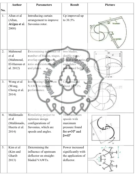
There are some researches dealing with increasing of Savoniuswind turbine performance. Altan et al (Altan, Atılgan et al. 2008) conducted a study to introduce a new curtaining arrangement to improve the performance of Savonius rotors. The curtain arrangement was placed in front of the rotor preventing the negative torque opposite the rotor rotation. The maximum power coefficient of the Savonius wind rotor is increased to about 38.5% with the optimum curtain arrangement.
Mahmoud et al (Mahmoud, El-Haroun et al. 2012) carried out an experimental study to determine the most effective operation parameters on different geometries of Savonius wind turbine such as number of blades, stages, overlap ratio, aspect ratio and existence of end plates. The research found that the two blades rotor is more efficient than three and four ones. Double stage rotors have higher performance. The rotors without overlap ratio (β) have better performance. The end plates give higher efficiency. And the power coefficient increases accordingly with the aspect ratio raise (α).
Wong et al (Wong, Chong et al. 2014) conducted a numerical study to introduce the power augmented shroud which is known as the new design of Omni Directional Guide Vane (ODGV) on Vertical Axis Wind Turbine (VAWT) to improve small wind turbine performance. New ODGV design are divided into two segments with same length with the standard guide vane plate and bent at 10° angle. The new design reduces the cut in speed better. The coefficient of power increases about 31.65% compared to the original ODGV design. Furthermore, when it compared to the bare VAWT, it increases about 147.1%.
Maldonado et al (Maldonado, Huerta et al. 2014) studied simulation project to optimize the design configuration of Savonius rotors. A study of speeds and maximum pressures as a function of incidence angles in the windows proposals for the Savonius rotor was proposed. The maximum speed with maximum pressure were found for the angles α=30° and β=40°. The proposed input configurations in curtains increase the speed of the Savonius rotor and consequently increase the Cp. The configuration α =30° and β=40 ° can increase the on-coming speed to the Savonius rotor of 5 m/s to 8.18 m/s increases by 62%.
Kim et al (Kim and Gharib 2013) studied experimentally influence of upstream deflector on performance of straight-bladed VAWTs. The power of wind turbine increases significantly when the turbine placed behind the deflector. Further, there is higher power
5
increase when the turbine placed outside of the near-wake of the deflector. The height of deflector has important influence. The power increases constantly on each turbine positions when the height between deflector and turbine is parallel.
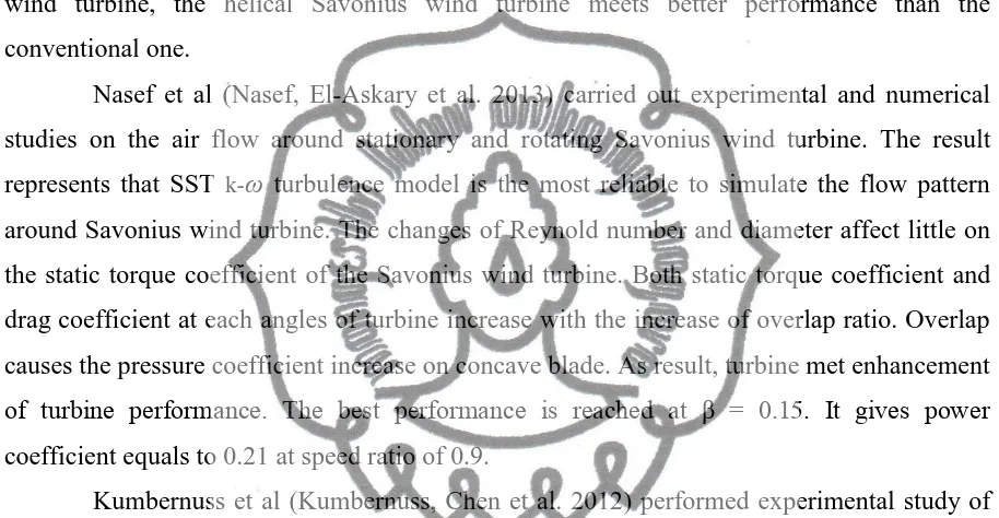
Damak et al (Damak, Driss et al. 2013) conducted experimental study to increase Savonious wind turbine by proposing a 180° twisted-helical Savonius wind turbine. They studied the aerodynamic behavior of helical Savonius wind turbine. The result shows that the Re variation and overlap ratio affect global characteristics of the helical Savonius wind around Savonius wind turbine. The changes of Reynold number and diameter affect little on the static torque coefficient of the Savonius wind turbine. Both static torque coefficient and drag coefficient at each angles of turbine increase with the increase of overlap ratio. Overlap causes the pressure coefficient increase on concave blade. As result, turbine met enhancement of turbine performance. The best performance is reached at β = 0.15. It gives power coefficient equals to 0.21 at speed ratio of 0.9.
Kumbernuss et al (Kumbernuss, Chen et al. 2012) performed experimental study of Savonius wind turbine with various overlap ratios and shift angles. Results determine that higher overlap ratio gives higher impact on increasing the starting characteristic of Savonius wind turbine than any phase shift angles. There is a certain phase shift angle related to a certain velocity that will increase the power coefficient. Furthermore, the recorded data shows an unexpected second performance peak that appeared at higher tip speed ratios.
Jeon et al (Jeon, Jeong et al. 2014) carried out experimental study of the end plate influence on the aerodynamic performance of helical Savonius wind turbine with a twist angle of 180° of two semicircular buckets. Four helical Savonius wind turbine models were tested by a subsonic open-circuit type wind tunnel. The results show that the maximum power coefficient and tip ratio increased linearly with the increase of end plate ratio up to 1.0. The application both top and bottom circular end plates on turbine increase significantly the power coefficient up to 36% compared without end plates.
6
Table 2.1 Resume of Previous Study
No.
Author Parameters Result Picture
7 2.2. Basic Theory
2.2.1. Type of Wind Turbine
8
axis rotation, wind turbine is classified into horizontal axis wind turbine and vertical axis wind turbine.
Figure 2.1 Aaerodynamic forces of Wind Turbine (Hau 2006)
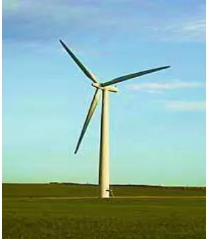
2.2.2. Horizontal Axis Wind Turbine
Horizontal axis wind turbines (HAWT) have rotation axis horizontal to the ground and parallel to the wind stream (Fig. 2.2). Most of the commercial wind turbines are based on this category. Horizontal axis machines have some advantages such as low cut-in wind speed and easy furling. In general, they show relatively high power coefficient. The generator and gearbox of turbines are placed over the tower. Which it makes the design is more complex and expensive. Another disadvantage is the need for the tail or yaw drive to orient the turbine towards wind.
9
Based on the number of blades, horizontal axis wind turbines are classified as single bladed, two bladed, three bladed and multi bladed. The ratio between the actual blade areas to the swept area of a rotor is termed as the solidity. Multi bladed rotors are also called high solidity rotors. These rotors can start easily as more rotor area interacts with the wind initially. Some low solidity designs may require external starting. Based on the direction of receiving the wind, HAWT can be classified as upwind and down wind turbines. Upwind turbine‟s rotors face the wind directly. On the other hand, downwind machines are more flexible and may not require a yaw mechanism.
2.2.3. Vertical Axis Wind Turbine
The axis of rotation of vertical axis wind turbine (VAWT) is vertical to the ground and almost perpendicular to the wind direction. The VAWT can receive wind from any direction. So complicated yaw devices can be eliminated. The generator and the gearbox can be housed at the ground level. It makes the tower design simple and more economical. Moreover the maintenance of these turbines can be done at the ground level. Pitch control is not required when used for synchronous applications. The major disadvantage of some VAWT is that they are usually not self-starting. Additional mechanisms may be required to start the turbine, once it is stopped. As the rotor completes its rotation, the blades have to pass through aerodynamically dead zones which will result in lowering the system efficiency. There are chances that the blades may run at extreme high speeds causing the system to be failed, if it is not controlled properly. Further, guy wires are required to support the tower structure which may pose practical difficulties.
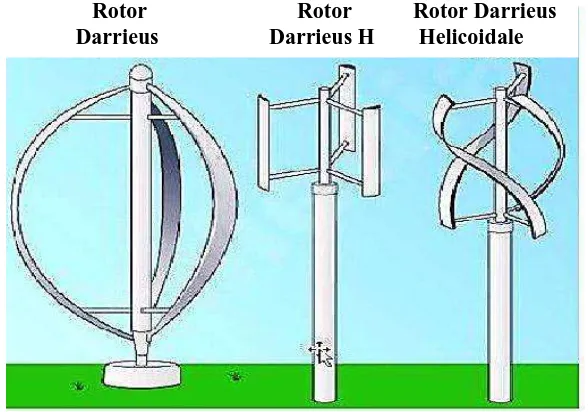
Figure 2.3 Vertical Axis Wind Turbines of Darrieus
Rotor Rotor Rotor Darrieus Darrieus Darrieus H Helicoidale
10 2.2.3.1. Darrieus Wind Turbine
Darrieus rotor, named after its inventor Georges Jeans Darrieus, works due to the lift force generated from a set of airfoils (Fig. 2.3). The original design blades are shaped like egg beaters or troposkein (turning rope) and are under pure tension while in operation. This typical blade helps to reduce bending stress experienced by the blades. There are several variations in the Darrieus design of which some are with straight vertical blades, usually called Giromills. Darrieus rotor usually works at high tip speed ratio which makes it attractive for wind electric generators. However, they are not self-starting and require external „excitation‟ to cut-in. Moreover, the rotor produces peak torque only twice per revolution.
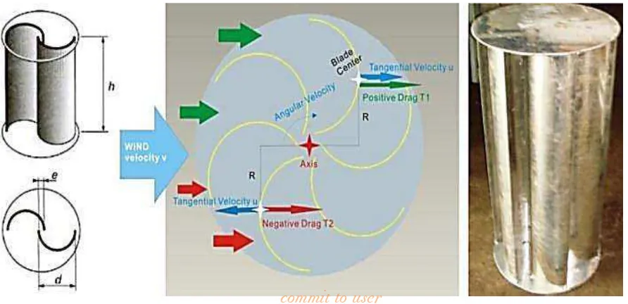
2.2.3.2. Savonius Wind Turbine
The Savonius wind turbine, invented by S.J. Savonius, is a vertical axis machine consisting of two half cylindrical (or elliptical) blades arranged in „S‟ shape (Fig.2.4). Convex of one side and the concave side of the other are facing the wind at a time as shown in Fig.2.5. The basic driving force of Savonius rotor is drag. The drag coefficient of a concave surface is more than the convex surface. Hence, the concave half cylinder that facing the wind will experience more drag force than the convex one, thus force the rotor to rotate. Sometimes two or more rotors fixed one over the other at 90° offset may be used to reduce the torque fluctuations during rotation. Another way to get its efficiency is adding deflector augmenters with the rotor. The augmenter shades the convex half facing the wind and directs the flow to the concave half thus enhancing the performance.
11
Being drag machines, Savonius rotors have lower power coefficient. However, some experimental rotors have shown power coefficient up to 35 percent. These rotors have high solidity and thus high starting torque. They work at low tip speed ratios, with the maximum of about one. They have simple construction and it even can be made from oil barrels cut in two halves lengthwise. Hence they are preferred for high torque-low speed applications like water pumping.
Figure 2.5 Principle of Savonius Rotor(Sathyajith 2006) 2.2.3.3. Advantages of Savonius Wind Turbine
Savonius wind turbine has some advantages as follow:
1. Due to the relative simplicity of the turbine assembly, this type of turbine can be constructed simply without complex fabrication and cost effectively.
2. Similarly because of the relative simplicity of the design. Savonius wind turbines are reliable and less prone to damage. This is also due to the relative solidity of the design. 3. Being a drag type, the Savonius turbine has a high starting torque and hence can
self-starting even in low wind speeds.
4. Like all VAWT, Savonius turbines are able to receive wind from any directions. And being drag type, they are less affected by air turbulence.
2.2.3.4. Method to Improve Savonius Wind Turbine Performance
There are argumentations to improve Savonius wind turbine performance that explained in some past literatures.
1. Deflector Plate
As one way to improve Savonius wind turbine efficiency, deflector plate is plates that placed in front of the Savonius rotor in order to prevent negative torque and directing wind onto concave blade (Altan, Atılgan et al. 2008; Mohamed and Thévenin 2010).
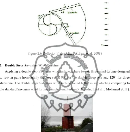
12
Figure 2.6 Deflector Plate (Altan, Atılgan et al. 2008)
2. Double Steps Savonius Wind Turbine
Applying a double-step Savonius wind turbine, where two or three wind turbine designed to row in pairs horizontally that are set at 90° for the double steep one and 120° for three steps one. The double steps Savonius wind turbine found better in self-starting comparing to the standard Savonius wind turbine (single wind turbine)(Hayashi, Li et al. ; Mohamed 2011).
Figure 2.7 Double-step Savonius Wind Turbine
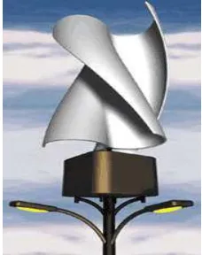
3. Twisted Blade Savonius Wind Turbine
Twisted-blade Savonius wind turbine was investigated to improve its efficiency. Based on performance analysis has been done on the starting characteristic, static torque and rotation speed. The result shows that the twisted-blade Savonius wind turbine has potential values due to its smooth running, high efficiency and the self-starting ability is better than conventional or standard Savonius wind turbine(Mohamed 2011; Damak, Driss et al. 2013).
13
Figure 2.8 Twisted Savonius Wind Turbine
4. Modified Savonius Wind Turbine Parameter
Various Savonius rotor parameters were studied to understand the effect of various parameters toward efficiency of Savonius wind turbine performance. Manipulation of parameters were done determine efficiency and to know the best condition of Savonius rotor performance such as the effect of end plates, aspect ratio, number buckets, the influence of bucket spacing and overlap, the influence of Reynold‟s number and turbulence intensity, the influence of stator (Akwa, Vielmo et al. 2012; Mahmoud, El-Haroun et al. 2012).
14
Figure 2.9 Modification of Savonius Wind Turbine Parameter(Akwa, Vielmo et al. 2012)
15
5. Guide Vane
Deflector plates that designed and placed around the Savonius wind turbine to increase turbine performance. Besides to direct the wind on to concave blade (wind concentrator function) and to avoid negative torque, guide vane also can be used to increase starting characteristic of Savonius wind turbine and it also decreases its fluctuation (OGAWA, TAHARA et al. 1986; Chong, Fazlizan et al. 2010; Mohamed 2011).
Figure 2.10 Savonius Wind Turbines with Guide Vane(OGAWA, TAHARA et al. 1986)
2.2.4. Principle of Wind Energy Conversion
The kinetic energy of a stream of air with mass (m) and moving with a velocity (v) is given by
(1)
2.2.4.1. Betz’s Elementary Momentum Theory
The extraction of mechanical energy from a stream of moving air with the help of a disk shaped, rotating wind energy converter follows its own basic rules. The credit for having recognised this principle is owed toAlbert Betz.Between 1922 and 1925, Betz published writings in which he was able to show that, by applying elementary physical laws, the mechanical energy extractable from an air stream passing through a given cross-sectional area is restricted to a certain fixed proportion of the energy or power contained in the air stream. Moreover, he found that optimal power extraction could only be realised at a certain
16
ratio between the flow velocity of air in front of the energy converter and the flow velocity behind the converter (Hau 2006).
Figure 2.11 Flow conditions due to the extraction of mechanical energy from a free-stream air flow according to the elementary momentum theory (Hau 2006)
Considering a certain cross-sectional area A, through which the air passes at velocity (v), the volume V flowing through during a certain time unit, the so-called volume flow, is:
(m3/s) (2)
and the mass flow with the air density ρ is:
(kg/s) (3)
The equations expressing the kinetic energy of the moving air and the mass flow yield the amount of energy passing through cross-section A per unit time. This energy is physically identical to the power P:
(Watt) (4)
Here, v1 is the undelayed free-stream velocity, the wind velocity, before it reaches the converter, whereas v2 is the flow velocity behind the converter.The mechanical energy which the disk-shaped converter extracts from the airflow corresponds to the power difference of the air stream before and after the converter:
(Watt) (5) Maintaining the mass flow (continuity equation) requires that:
(6)
Hereafter:
(Watt) (7)
17
From this equation it follows that, in purely formal terms, power would have to be at its maximum when v2 is zero, namely when the air is brought to a complete standstill by the converter. However, this result does not make sense physically. If the outflow velocity v2 behind the converter is zero, then the inflow velocity before the converter must also become zero, implying that there would be no more flow through the converter at all. As could be expected, a physically meaningful result consists in a certain numerical ratio of v2/v1 where the extractable power reaches its maximum equation expressing the mechanical power of the converter. Using the law of conservation of momentum can be expressed as:
(N) (8)
According to the principle of “action equals reaction”, this force, the thrust,must be counteracted by an equal force exerted by the converter on the air flow. The thrust, so to speak, pushes the air mass at air velocity (v)‟, present in the plane of flow of the converter. The power required for this is:
(Watt) (9)
Equating these two expressions yields the relationship for the flow velocity v‟:
(Watt) (10)
Hereafter;
(m/s) (11)
Thus the flow velocity through the converter is equal to the arithmetic mean of v1 and v2:
(m/s) (12)
The mass flow thus becomes:
(kg/s) (13)
The mechanical power output of the converter can be expressed as:
(Watt) (14)
18
It is compared with the power of the free air stream which flows through the same cross sectional area A, without mechanical power being extracted from it. This power was:
(Watt) (15)
2.2.4.2. Power Coefficient and Tip Speed Ratio
When the wind stream passes the turbine, a part of its kinetic energy is transferred to the rotor and the air leaving the turbine carries the rest away. Actual power produced by a rotor would thus be decided by the efficiency with which this energy transfer from wind to the rotor takes place. This efficiency is usually termed as the power coefficient (Cp). Thus, the power coefficient of the rotor can be defined as the ratio of actual power developed by the rotor to the theoretical power available in the wind(Mathew 2006). It is expressed as follows:
(16)
After some re-arrangement, the power coefficient can be specified directly as a function ofthevelocity ratio v2/v1:
(17)
Figure 2.12 Power coefficient compared to the flow velocity ratio of the flow before and after the energy converter(Hau 2006)
19
The power coefficient, the ratio of the extractable mechanical power to the power contained in the air stream, therefore, now only depends on the ratio of the air velocities before and after the converter. If this inter relationship is plotted graphically naturally, an analytical solution can also be found easily, it can be seen that the power coefficient reaches a maximum at a certain velocity ratio (Fig.2.7). With v2/ v1 = 1/3, the maximum “ideal power coefficient” Cp becomes:
(18)
This is called Betz‟s limits where the ideal coefficient power will not over than the ideal number which is 0,593.
Speed is conventionally given as a non-dimensional ratio known as the tip speed ratio λ, which is the ratio of the speed of the rotor tip at radius R in meter, when rotating at ω radians per seconds, to the speed of the wind (v).
(19)
This graphic shows tip speed ratio (λ) and power coefficient (Cp) of various wind turbines.
Figure 2.13 Characteristic of PowerCoefficient and TipSpeed Ratio for some wind turbines(Hau 2006)
20 2.2.4.3. Torque
Apart from the rotor power, there are other parameters which are of significance in characterizing rotor performance. The most important of these is the behaviour of the torque. The rotor torque can present as follows:
(20)
Where the rotor radius R is the reference parameter. Since the torque can be calculated by dividing power by the rotational speed,the following simple relationship between power and torque coefficient is obtained:
(21)
The tip speed ratio can be given by the ratio between the power coefficient and torque coefficient of the rotor.
Figure 2.14 Characteristic of Torque Coefficient and
Tip Speed Ratio for Some Wind Turbines(Akwa, Vielmo et al. 2012)
21 CHAPTER III RESEARCH METHOD
3.1. Research Place
The research was conducted at Heat Transfer Laboratory of Mechanical Engineering Department of Engineering Faculty of Sebelas Maret University in Surakarta
3.2. Apparatus
a. Model of Vertical Axis Wind Turbine Savonius
Contrive the wind turbine model as following specifications: - Turbine diameter : 20 cm
- Axis height : 18 cm
- Overlap of blade : 1 cm - Number of blade : 2 blades - Material of blade : Aluminum
a. Two-blade Savonius Rotor b. Savonius Rotor with Guide Vane Figure 3.1 Models of Vertical Axis Wind Turbine Savonius
22
Figure 3.2 Savonius Wind Turbines with Guide Vane Model c. Guide Vane
This research uses four guide vane designs with the specification of each guide vane as follows:
Figure 3.3 Models of Various Guide Vane Design d. Wind Source
The source of wind for the turbine is fan. The velocity variants were 7.7 m/s, 8.6 m/s, 9.7 m/s, and 10.7 m/s.
23 e. Tachometer
It used to measure rotation speed (rpm) of the Savonius wind turbine f. Anemometer
It used to measure wind speed in front of and the turbine.
3.3. Research Procedure 1. Experiment Set-up
- Contrive the model of Savonius wind turbine based on its design
- Prepare and set up the instruments that will be used according to the following scheme:
Figure 3.4 Experiment set-up 2. Experiment Steps
- Experiment steps of Savonius wind turbine without guide vane
1) Turn on the fan 1.2 m in front of the Savonius wind turbine at wind velocity of 7.7 m/s and wait 3 minutes in order to attain steady wind flow to start taking data or measurement.
2) Measure the wind speed in front of Savonius wind turbine system from several points using anemometer.
3) Measure the rotation speed (rpm) on the axis of turbine using tachometer.
4) Repeat the step 2 and 3 for twice, so it would be got three data of wind speeds and rotation speeds.
5) Make an average of the three data of wind speeds and rotation speed above. The result will be the final data.
24
- Experiment steps of Savonius Wind Turbine with guide vane
1) Set-up the guide vane with the basic design to Savonius wind turbine.
2) Turn on the fan at the wind velocity of 7.7 m/s and wait for 3 minutes to attain steady wind slow before taking the measurement.
3) Measure the wind speed in front of wind turbine using anemometer. Take the data of wind speed in some points of wind turbine with guide vane area and average the data from the some spots. The several points were taken at center of Savonius rotor. Eight points were taken from guide vane system, which were four points at corner of inner height of guide vane, four points at corner of outer height of guide vane. Two points were about 5 cm away on above and under the Savonius rotor system. The two last points were about 5 cm away on left and right side of the Savonius rotor system. The result will be the final data.
4) Measure the rotation speed (rpm) on the axis of wind turbine using tachometer. 5) Repeat the step 1 to 4 for each guide vane designs, which are guide vane with tilt
angle of 15°, guide vane with tilt angle of 30° and guide vane with tilt angle of 45°.
6) Repeat the step 1 to 5 for each wind velocity.
3. Data analysis
The data that can be taken after experiments are the wind velocity (m/s) and the rotation speed (rpm) from the Savonius wind turbine without guide vane and Savonius wind turbine with variation dimension designs of guide vane. Further, it can be calculate to determine power coefficient (Cp), tip speed ratio (λ) and torque coefficient (Ct). Based on those calculations, the correlation between wind speeds (m/s), rotation (rpm), tip speed ratio (λ), power coefficient (Cp) and torque coefficient (Ct) can be clearly drawn on figure either for Savonius wind turbine without guide vane or the Savonius wind turbine with various designs of guide vane that is presented on the present study.
25 3.4. Steps of Research Diagram
Diagram of present research was conducted based on following diagram flow:
Figure 3.5 Steps of Research Diagram
The first step conducted this research with contriving the model of small-scale wind turbine for low speeds. The next step contrived guide vanes based on the model of this study. There were four designs of guide vane, which are basic design, basic design plus 15°, 30°, and 45°. Further, data retrievals conducted starting with Savonius wind turbine without guide vane and continued by Savonius wind turbine with basic design of guide vane, Savonius with guide vane design plus 15°, 30°, and 45°. The data that taken were wind velocity, rotational speed (RPM), and voltage. Based on the data, calculating Power Coefficient (Cp), Tip Speed
26
Ratio, and Torque Coefficient (Ct) were conducted. Analysis conducted based on the calculation of Cp, tip speed ratio and Ct. Finally, conclusion could be gotten and this research finished.
27 voltage (volt), current (ampere) and power (P). Hence these data will be calculated to know Savonius wind turbine performance. Here are the wind speed variations in the experiments:
No
28 4.2. Discussion
Experiments have been done to determine performance of Savonius wind turbine. Those have carried out with various guide vane designs to know the effect of the design on efficiency of Savonius wind turbine performance. The performance of Savonius wind turbine with various guide vane designs compared to Savonius wind turbine without guide vane.
4.2.1. Power Coefficient
Figure 4.3 Correlation between Power Coefficient (Cp) and Velocity (v)
Figure 4.3 shows correlation between power coefficient (Cp) and wind speeds (v) of Savonius wind turbine without guide vane and with various designs of guide vane. There is increase of power that generated by Savonius wind turbine accordingly with the increase of wind speed (v).Figure 4.3 also illustrates that the addition of guide vane increased the Cp significantly compared to wind turbine without guide vane.
The guide vane blocked up the wind into convex blade and directed the wind into concave blade of wind turbine. It consequently increased rotor rotation, so that the rotor generated higher power than the rotor without guide vane at every wind speed. The maximum Cp of Savonius wind turbine without guide vane was attained 13.2 at 10.7 m/s. And the maximum Cp of Savonius wind turbine with basic design of guide vane 18.3 at the same wind speed. The power coefficient increased about 27.66% based on the maximum Cp that produced by rotor without and with basic design of guide vane.
29
which is 18 cm. And the guide vane was added a top and a bottom disc. Higher height of the guide vane helped to capture more wind that coming to the rotor. And the additional top and bottom discs deflect the wind on upper and bottom part of rotor. As result, the wind directed into Savonius rotor which has 18 cm height. The Cp increased about 43.30% compared toward without guide vane rotor.
Hence other designs of guide vane were basic design with additional tilt angle of 30°
and 45°. The outer blade of guide vane of tilt angle 30° increased to be 28.3 cm and 36 cm for guide vane with additional tilt angle of 45°. The maximum power coefficient generated by the rotor with both guide vanes were 32.1 for guide vane with additional 30° tilt angle and 38.7 for the guide vane design with additional tilt angle of 45°. It improves about 58.86% for rotor with 30° design of guide vane and up to 65.90% for the rotor with guide vane design plus tilt angle of 45° compared to Savonius rotor without guide vane.
3.4.2. Tip Speed Ratio
Figure 4.4 Correlation Tip Speed Ratio (λ) and Power Coefficient (Cp)
Figure 4.4 shows the relation between power coefficient (Cp) and Tip Speed Ratio (TSR) of Savonius wind turbine without guide vane and with various designs of guide vane. There are increases of Cp of Savonius wind turbine accordingly with the increase of TSR. Based on the above chart, maximum Cp of Savonius wind turbine without guide vane was attained 13.2 at 10.7 m/s when TSR reached 0.42.
The maximum Cp of Savonius wind turbine reached 18.3 while the TSR was 0.48 by additional of basic guide vane design. TSR improved about 12.6%. TSR increased 23.65% on
30
the Savonius rotor with second guide vane design by adding tilt angle of 15°, which is 0.54 compared to Savonius rotor without guide vane.
The next experiment used the third design of guide vane by adding tilt angle of 30°, the maximum TSR attained 0.59 which means increased about 29.15% compared to without guide vane rotor. The last design of guide vane with additional tilt angle of 45°, the maximum TSR was 0.62 and it increased about 32.54% compared to without guide vane rotor. The additional of guide vane increaced the tip speed ratio, it might be caused by the guide vane that directed the wind on to concave blade and brougt more wind to the rotor blade. As result, the ratio speed of the wind increased.
4.2.3. Torque Coefficient
Figure 4.5 Correlation between Torque Coeffient and Velocity
31
Figure 4.5 and 4.6 illustrate correlation between coefficient torque (Ct) and wind speed (v) and correlation between Ct and tip speed ratio (λ). The figure describes that Ct of rotor without guide vane increased at each velocity. There was increasing of Ct compared to the rotor with basic guide vane design. Maximum Ct that produced by the rotor without guide vane was 31.8 while the tip speed ratio (λ) reached 0.42 and the rotor with basic design of guide vane attained the Ct of38.4 at 10.7 m/s and at the λ of 0.48, which means increaced about 17.23% compared to rotor without guide vane.
Other experiments used basic design of guide vane with additional tilt angle of 15°, maximum Ct of rotor was 47.7 at the λ of 0.44 that is improves about 33.31% compared to maximum Ct of rotor without guide vane, however it was attained at the velocity of 8.6 m/s.
The Savonius rotor with the third design of guide vane with additional tilt angle of 30°, the Ct maximum reached up to 60.1 at the velocity of 8.6 m/s and at the λ of 0.50, which means improves about 47.09% compared to the rotor without guide vane. And the last design of guide vane with additional of tilt angle of 45°, the Ct of Savonius rotor was attained up to 66.1 at the velocity of 8.6 m/s and at the λ of 0.53. It was improved about 51.87%.
Therefore, Ct started to decrease at velocity of 9.7 m/s, when the value of λ increased accordingly with the increase of velocity. The decreace happened on the rotor with basic design guide vane with additional tilt angle of 15°, 30°, and 45°.The decreace happened might because of the characteristic of the Savonius wind turbine that Ct increaces liniear due to the decrease of tip speed ratio (λ). So that when the tip speed ratio value increaces, the Ct decreased as happening in the present study.
4.3 Comparison of Guide Vane Influence on Savonius Wind Turbine Performance with Previous Study
There is previous study that has been conducted to improve Savonius wind turbine through guide vane as present study. Table 4.3 described comparison the results of this study with previous one which was conducted by WT Chong at al in 2010. It compares maximum power coefficient that reached on certain tip speed ratio value.
Table 4.3 Comparison of Maximum Power Coefficient and Maximum Tip Speed Ratio with previous study
32
Maximum power coefficient of WT Chong‟s study reached up to 0.26 at the tip speed ratio of 0.95. In other hand, power coefficient of this study reached maximum value at 0.39 at the tip speed ratio of 0.62. The power coefficient of WT Chong study increased up to 56.86% compared with Savonius wind turbine without guide vane. And in this study, Power coefficient increased up to 65.89% compared with Savonius wind turbine without guide vane. It can be concluded that guide vane addition improved Savonius wind turbine performance.
33 CHAPTER V CONCLUSION
In present work, a series of experiment has been carried out. This experiment used two-blade Savonius wind turbine without guide vane and with various designs of guide vane, which are basic design of guide vane, basic design with additional tilt angle of 15°, 30° and 45°. It can be concluded as follows:
1. The best design of guide vane is the basic design with additional tilt angle of 45°. The power generated by turbine increases up to 65.89% compared without guide vane turbine. 2. It has been proven that the addition of guide vane support the improvement of the
Savonius wind turbine. The guide vane helps to block up wind direction on to convex blade and direct it to concave blade. They are able capture the wind and prevented the wind that might be escaped to the sides, upper, or bottom sides. And the Savonius rotor met its efficiency.
3. Coefficient of power (Cp) increases accordingly with the increase of wind velocity and at same time Cp increase with the increase of tip speed ratio (λ) in this present study.
4. Torque coefficient (Ct) increased with the increasing of wind velocity (v) and tip speed ratio. However, Ct started to decreace on Savonius rotor with guide vane design plus tilt angle of 15°, 30°, and 45° at the wind speed of 9.7 m/s.
34 REFERENCE
Akwa, J. V., H. A. Vielmo, et al. (2012). "A review on the performance of Savonius wind turbines."
Renewable and Sustainable Energy Reviews 16(5): 3054-3064.
Alam, F., A. Ali, et al. (2012). "Status of power generation by domestic scale wind turbines in
Australia." Procedia Engineering 49: 205-212.
Alta , B. D. a d M. Atılga . "A stud o i creasi g the perfor a ce of Sa o ius i d rotors."
Journal of mechanical science and technology 26(5): 1493-1499.
Alta , B. D., M. Atılga , et al. 8 . "A e perimental study on improvement of a Savonius rotor
performance with curtaining." Experimental thermal and fluid science 32(8): 1673-1678.
Chong, W. T., A. Fazlizan, et al. (2010). Design and Wind Tunnel Testing of a Savonius Wind Turbine
Integrated with the Omni-Direction-Guide-Vane. Proceedings of the Solar Conference.
Damak, A., Z. Driss, et al. (2013). "Experimental investigation of helical Savonius rotor with a twist of
180." Renewable Energy 52: 136-142.
Hau, E. (2006). "Wind turbines: fundamentals, technologies, application, economics."
Hayashi, T., Y. Li, et al. "Suzuki (2004) Proceedings of European Wind Energy Conference and
Exhibition." Wind tunnel test on a three stage out phase Savonius rotor, London, England.
Jeon, K. S., J. I. Jeong, et al. (2014). "Effects of end plates with various shapes and sizes on helical
Savonius wind turbines." Renewable Energy.
Kim, D. and M. Gharib (2013). "Efficiency improvement of straight-bladed vertical-axis wind turbines
with an upstream deflector." Journal of Wind Engineering and Industrial Aerodynamics 115:
48-52.
Kumbernuss, J., J. Chen, et al. (2012). "Investigation into the relationship of the overlap ratio and
shift angle of double stage three bladed vertical axis wind turbine (VAWT)." Journal of Wind
Engineering and Industrial Aerodynamics 107: 57-75.
Mahmoud, N., A. El-Haroun, et al. (2012). "An experimental study on improvement of Savonius rotor
performance." Alexandria Engineering Journal 51(1): 19-25.
Maldonado, R., E. Huerta, et al. (2014). "Design, Simulation and Construction of a Savonius Wind
Rotor for Subsidized Houses in Mexico." Energy Procedia 57: 691-697.
Mathew, S. (2006). "Wind Energy Fundamentals, Resource Analysis and Economics."
Mohamed, M. and D. Thévenin (2010). Performance optimization of a Savonius turbine considering
different shapes for frontal guiding plates. Proceedings of the 10th international congress of
fluid dynamics (ICFD 10), Ain Soukhna, Egypt.
35
Mohamed, M. H. A. (2011). "Design optimization of savonius and wells turbines." Ottovon-Guericke
University Magdeburg.
Nasef, M., W. El-Askary, et al. (2013). "Evaluation of Savonius rotor performance: static and dynamic
studies." Journal of Wind Engineering and Industrial Aerodynamics 123: 1-11.
OGAWA, T., K. TAHARA, et al. (1986). "Wind tunnel performance data of the Savonius rotor with
circular guide vanes." Bulletin of JSME 29(253): 2109-2114.
Sathyajith, M. (2006). Wind energy: fundamentals, resource analysis and economics, Springer
Science & Business Media.
Tong, W. (2010). Wind power generation and wind turbine design, WIT press.
Wong, K., W. Chong, et al. (2014). "The Design and Flow Simulation of a Power-augmented Shroud
for Urban Wind Turbine System." Energy Procedia 61: 1275-1278.
36 APPENDIX
Table A. 1 Data Experiment of Savonius Wind Turbine without Guide Vane
No Frequency Velocity (m/s)
Table A. 2 Data Experiment of Savonius Wind Turbine with Basic Design of Guide Vane
No Frequency Velocity (m/s)
Table A. 3 Data Experiment of Savonius Wind Turbine with Basic Design of Guide Vane and Additional Tilt Angle of 15°
37
Table A. 4 Data Experiment of Savonius Wind Turbine with Basic Design of Guide Vane and Additional Tilt Angle of 30°
No Frequency Velocity (m/s)
Table A. 5 Data Experiment of Savonius Wind Turbine with Basic Design of Guide Vane and Additional Tilt Angle of 45°