Revisions, January 2003
Manual of Steel Construction
Load and Resistance Factor Design
3rd Edition
A
MERICANI
NSTITUTE OFS
TEELC
ONSTRUCTIONby
American Institute of Steel Construction, Inc.
ISBN 1-56424-051-7
All rights reserved. This book or any part thereof
must not be reproduced in any form without the
written permission of the publisher.
The information presented in this publication has been prepared in accordance
with recognized engineering principles and is for general information only. While
it is believed to be accurate, this information should not be used or relied upon
for any specific application without competent professional examination and
verification of its accuracy, suitability, and applicability by a licensed professional
engineer, designer, or architect. The publication of the material contained herein
is not intended as a representation or warranty on the part of the American
Institute of Steel Construction or of any other person named herein, that this
information is suitable for any general or particular use or of freedom from
infringement of any patent or patents. Anyone making use of this information
assumes all liability arising from such use.
Caution must be exercised when relying upon other specifications and codes
developed by other bodies and incorporated by reference herein since such
material may be modified or amended from time to time subsequent to the
printing of this edition. The Institute bears no responsibility for such material other
than to refer to it and incorporate it by reference at the time of the initial
publication of this edition.
Printed in the United States of America
First Printing: November 2001
Second Printing: January 2003
A
MERICANI
NSTITUTE OFS
TEELC
ONSTRUCTIONPREFACE
This 3
rdEdition
LRFD Manual of Steel Construction
is the twelfth major update of the
AISC Manual of Steel Construction, which was first published in 1927. With this revision,
member and connection design information has been condensed back into a single
volume. It has been reorganized and reformatted to provide practical and efficient access
to the information it contains, with a roadmap format to guide the user quickly to the
applicable specifications, codes and standards, as well as the applicable provisions in
those standards.
The following specifications, codes and standards are included in or with this Manual:
•
1999
LRFD Specification for Structural Steel Buildings
•
2000
LRFD Specification for Steel Hollow Structural Sections
•
2000
LRFD Specification for Single-Angle Members
•
2000
RCSC Specification for Structural Joints Using ASTM A325 or A490 Bolts
•
2000
Code of Standard Practice for Steel Buildings and Bridges
•
AISC Shapes Database V3 CD
The following major improvements have been made in this revision:
•
Workable gages for flange fasteners have been reintroduced.
•
The
revised
T
,
k
and
k
1 values for W-shapes and the 0.93 wall-thickness reductionfactor for HSS have been considered.
•
Guidance is provided on the new OSHA safety regulations, stability bracing
requirements and proper material specification.
•
New information is provided on design drawing information requirements, criteria
needed for connection design, mill, fabrication and erection tolerances, façade
issues, temperature effects and fire protection requirements with summaries of
common UL assemblies.
•
Shape information has been updated to the current series.
•
Coverage of round HSS has been added.
•
Dimensions and properties have been added for double channels back-to-back.
•
Tables of surface and box perimeter, weight/area-to-perimeter ratios and surface
areas have been expanded to cover all common structural shapes.
•
A new section on properly specifying materials, including shapes, plates, fasteners
and other products, has been added.
•
New information on corrosion protection and seismic design has been added.
•
A new section has been added with design aids for tension members, including
explicit consideration of net section requirements to ensure connectable member
selection.
•
Beam selection tables are included for selection based upon
I
x,Z
x,I
y, andZ
y.•
Beam
charts
(
φ
M
n vs.L
b) are plotted for both W-shapes and channels.•
New floor plate deflection and bending design aids have been added.
•
Additional beam diagrams and formulas have been added.
•
A new section has been added with design aids for W-shape beam-columns.
•
New bolt length selection tables have been added.
•
Bolt entering and tightening clearances have been updated.
A
MERICANI
NSTITUTE OFS
TEELC
ONSTRUCTIONan update of Disque’s historic “type 2 with wind” moment connection design
approach.
•
Previous limitations on the use of moment end-plate connections have been
relaxed.
•
Information on the design of anchor rods has been updated, including a new table
of minimum dimensions for washers used with anchor rods.
•
Composite member tables have been updated to include coverage of both 4 ksi
and 5 ksi concrete.
•
A cross-reference between U.S. customary and Metric shapes series has been
included.
In addition, many other improvements have been made throughout this Manual.
By the AISC Committee on Manuals and Textbooks,
William A. Thornton, Chairman
Charles J. Carter
Robert O. Disque
Marshall T. Ferrell
Lanny J. Flynn
Mark V. Holland
Bill R. Lindley II
Leonard R. Middleton
William C. Minchin
Thomas M. Murray
Barry L. Barger, Vice Chairman
Charles R. Page
Davis G. Parsons II
David T. Ricker
Marc L. Sorenson
Scott T. Undershute
Gary C. Violette
Michael A. West
Heath E. Mitchell, Secretary
Table 1-5.
C-Shapes
(American Standard Channels)
Dimensions
Shape Area,
A Depth,d
Web Flange Distance
Thickness,
tw
tw
2
Width,
bf
Thickness,
tf k T
Work-able Gage†
in.2 in. in. in. in. in. in. in. in.
C15×50 14.7 15.0 15 0.716 11/16 3/8 3.72 33/4 0.650 5/8 17/16 121/8 21/4
×40 11.8 0.520 1/2 1/4 3.52 31/2 2
×33.9 9.95 0.400 3/8 3/16 3.40 33/8 2
C12×30 8.81 12.0 12 0.510 1/2 1/4 3.17 31/8 0.501 1/2 11/8 93/4 13/4
×25 7.34 0.387 3/8 3/16 3.05 3
×20.7 6.08 0.282 5/16 3/16 2.94 3
C10×30 8.81 10.0 10 0.673 11/16 3/8 3.03 3 0.436 7/16 1 8 13/4
×25 7.34 0.526 1/2 1/4 2.89 27/8 13/4
×20 5.87 0.379 3/8 3/16 2.74 23/4 11/2
×15.3 4.48 0.240 1/4 1/8 2.60 25/8 11/2
C9×20 5.87 9.00 9 0.448 7/16 1/4 2.65 25/8 0.413 7/16 1 7 11/2
×15 4.41 0.285 5/16 3/16 2.49 21/2 13/8
×13.4 3.94 0.233 1/4 1/8 2.43 23/8 13/8
C8×18.75 5.51 8.00 8 0.487 1/2 1/4 2.53 21/2 0.390 3/8 15/16 61/8 11/2
×13.75 4.04 0.303 5/16 3/16 2.34 23/8 13/8
×11.5 3.37 0.220 1/4 1/8 2.26 21/4 13/8
C7×14.75 4.33 7.00 7 0.419 7/16 1/4 2.30 21/4 0.366 3/8 7/8 51/4 11/4 ×12.25 3.60 0.314 5/16 3/16 2.19 21/4
×9.8 2.87 0.210 3/16 1/8 2.09 21/8
C6×13 3.81 6.00 6 0.437 7/16 1/4 2.16 21/8 0.343 5/16 13/16 43/8 13/8
×10.5 3.08 0.314 5/16 3/16 2.03 2 11/8
×8.2 2.39 0.200 3/16 1/8 1.92 17/8 11/8
C5×9 2.64 5.00 5 0.325 5/16 3/16 1.89 17/8 0.320 5/16 3/4 31/2 11/8 ×6.7 1.97 5.00 5 0.190 3/16 1/8 1.75 13/4 0.320 5/16 3/4 31/2 – C4×7.25 2.13 4.00 4 0.321 5/16 3/16 1.72 13/4 0.296 5/16 3/4 21/2 1
×5.4 1.58 0.184 3/16 1/8 1.58 15/8 –
×4.5 1.32 0.125 1/8 1/16 1.58 15/8 –
C3×6 1.76 3.00 3 0.356 3/8 3/16 1.60 15/8 0.273 1/4 11/16 15/8 –
×5 1.47 0.258 1/4 1/8 1.50 11/2 –
×4.1 1.20 0.170 3/16 1/8 1.41 13/8 –
×3.5 1.03 0.132 1/8 1/16 1.37 13/8 –
†See definition of “Workable Gage” in Nomenclature section at the back of this Manual.
– in Workable Gage column indicates that flange is too narrow to allow tabulation of a workable gage.
Rev.
11/1/02
Shape k Wt. Area,
A
Axis X-X
I S r y Z yp
in. lb/ft in.2 in.4 in.3 in. in. in.3 in.
L5×31/2×3/4 13/16 19.8 5.82 13.9 4.26 1.55 1.74 7.60 1.12 ×5/8
11/16
16.8 4.93 12.0 3.63 1.56 1.69 6.50 1.06
×1/2 15/16 13.6 4.00 9.96 2.97 1.58 1.65 5.33 0.997
×3/8 13/16 10.4 3.05 7.75 2.28 1.59 1.60 4.09 0.933
×5/16 3/4 8.72 2.56 6.58 1.92 1.60 1.57 3.45 0.901
×1/4 11/16 7.03 2.07 5.36 1.55 1.61 1.55 2.78 0.868
L5×3×1/2 15/16 12.8 3.75 9.43 2.89 1.58 1.74 5.12 1.25
×7/16 7/8 11.3 3.31 8.41 2.56 1.59 1.72 4.53 1.21
×3/8 13/16 9.74 2.86 7.35 2.22 1.60 1.69 3.93 1.18
×5/16 3/4 8.19 2.41 6.24 1.87 1.61 1.67 3.32 1.15
×1/4 11/16 6.60 1.94 5.09 1.51 1.62 1.64 2.68 1.12
L4×4×3/4 11/8 18.5 5.43 7.62 2.79 1.18 1.27 5.02 0.679
×5/8 1 15.7 4.61 6.62 2.38 1.20 1.22 4.28 0.576
×1/2 7/8 12.7 3.75 5.52 1.96 1.21 1.18 3.50 0.468
×7/16 13/16 11.2 3.30 4.93 1.73 1.22 1.15 3.10 0.413
×3/8 3/4 9.72 2.86 4.32 1.5 1.23 1.13 2.69 0.357
×5/16 11/16 8.16 2.40 3.67 1.27 1.24 1.11 2.26 0.300
×1/4 5/8 6.58 1.93 3.00 1.03 1.25 1.08 1.82 0.242
L4×31/2×1/2 11.9 3.50 5.30 1.92 1.23 1.24 3.46 0.497
×3/8 9.10 2.68 4.15 1.48 1.25 1.20 2.66 0.433
×5/16 7.65 2.25 3.53 1.25 1.25 1.17 2.24 0.401
×1/4 6.18 1.82 2.89 1.01 1.26 1.14 1.81 0.368
L4×3×5/8 13.6 3.99 6.01 2.28 1.23 1.37 4.08 0.810
×1/2 11.1 3.25 5.02 1.87 1.24 1.32 3.36 0.747
×3/8 8.47 2.49 3.94 1.44 1.26 1.27 2.60 0.683
×5/16 7.12 2.09 3.36 1.22 1.27 1.25 2.19 0.651
×1/4 5.75 1.69 2.75 0.988 1.27 1.22 1.77 0.618
L31/2×31/2×1/2 7/8 11.1 3.27 3.63 1.48 1.05 1.05 2.66 0.466
×7/16 13/16 9.82 2.89 3.25 1.32 1.06 1.03 2.36 0.412
×3/8 3/4 8.51 2.50 2.86 1.15 1.07 1.00 2.06 0.357
×5/16 11/16 7.16 2.10 2.44 0.969 1.08 0.979 1.74 0.301
×1/4 5/8 5.79 1.70 2.00 0.787 1.09 0.954 1.41 0.243
L31/2×3×1/2 7/8 10.3 3.02 3.45 1.45 1.07 1.12 2.61 0.480
×7/16 13/16 9.09 2.67 3.10 1.29 1.08 1.09 2.32 0.446
×3/8 3/4 7.88 2.32 2.73 1.12 1.09 1.07 2.03 0.411
×5/16 11/16 6.65 1.95 2.33 0.951 1.09 1.05 1.72 0.375
×1/4 5/8 5.38 1.58 1.92 0.773 1.10 1.02 1.39 0.336
L31/2×21/2×1/2 7/8 9.41 2.76 3.24 1.41 1.08 1.20 2.52 0.736
×3/8 3/4 7.23 2.12 2.56 1.09 1.10 1.15 1.96 0.668
×5/16 11/16 6.10 1.79 2.20 0.925 1.11 1.13 1.67 0.633
×1/4 5/8 4.94 1.45 1.81 0.753 1.12 1.10 1.36 0.596
15/16 13/16 3/4 11/16
15/16 13/16 3/4 11/16
Rev.
Table 1-55.
S-Shapes, M-Shapes, and Channels
∗Back of square and centerline of web to be parallel when measuring “out-of-square”
Permissible Cross-Sectional Variations
Shape Depth, in.Nominal,
Aa
Over Under Over Under
3 to 7, incl. 3/32 1/16 1/8 1/8 Channels Over 7 to 14,
incl. 1/8 3/32 1/8 5/32 1/32 –
Over 14 3/16 1/8 1/8 3/16
Permissible Variations in Length
Shape
Variations Over Specified Length for Lengths Givenc, in. 5 to 10 ft,
Mill Straightness Tolerances
dCamber 1/
8in.×(total length, ft)5
Sweep Due to the extreme variations in flexibility of these shapes, permitted variations for sweep aresubject to negotiation between the manufacturer and purchaser for the individual sections involved.
Other Permissible Rolling Variations
Area and Weight ±2.5 percent theoretical or specified amount.
Ends Out of Square S-shapes, M-shapes and channels1/64in. per in. of depth. – indicates that there is no requirement.
aAis measured at center line of web for beams and at back of web for channels. bT
+T′applies when flanges of channels are toed in or out.
cThe permitted variation under the specified length is 0 in. for all lengths. There are no requirements for lengths over 65 ft. dThe tolerances herein are taken from ASTM A6 and apply to the straightness of members received from the rolling mill,
mea-sured as illustrated in Figure 1-1. For tolerance on induced camber and sweep, see Code of Standard Practice Section 6.4.4.
Rev.
As shown in Table 2-3, the preferred material specification for twist-off-type tension-control
bolt assemblies is ASTM F1852, which offers a strength level that is equivalent to that of
ASTM A325 bolts. When a higher strength is desired, twist-off-type tension-control bolt
assemblies can be obtained in a strength level that is equivalent to that of ASTM A490 bolts
using the provisions for alternative-design fasteners in RCSC Specification Section 2.8. In
either case, Type 1 (medium-carbon steel) is most commonly specified. When atmospheric
corrosion resistance is desired, Type 3 can be specified.
Nuts
As shown in Table 2-3, the preferred material specification for heavy-hex nuts is ASTM
A563. The appropriate grade and finish is specified per ASTM A563 Table X1.1 according to
the bolt or threaded part with which the nut will be used. For steel-to-steel structural bolting
applications, the appropriate grade and finish is summarized in RCSC Specification Section
2.4. If its availability can be confirmed prior to specification, ASTM A194 grade 2H nuts are
permitted as an alternative as indicated in RCSC Specification Table 2.1.
Washers
As shown in Table 2-3, the preferred material specification for hardened steel washers is
ASTM F436. This specification provides for both flat and beveled washers. While standard
ASTM F436 washers are sufficient in most applications, there are several specific applications
when special washers are required. The special washer requirements in RCSC Specification
Section 6 apply when oversized or slotted holes are used in the outer ply of a steel-to-steel
structural joint. In anchor rod and other embedment applications, hole sizes are generally
larger than those for steel-to-steel structural bolting applications (see Table 14-2 for
maxi-mum anchor-rod hole sizes). Accordingly, washers used in such applications are generally
larger and may require design consideration for proper force transfer, particularly when the
anchorage is subject to tension. See Table 14-2 for anchor-rod washer sizes.
Compressible-Washer-Type Direct-Tension Indicators
When bolted joints are specified as pretensioned or slip-critical and the
direct-tension-indicator pretensioning method is used, ASTM F959 compressible-washer-type direct-tension
indicators are specified, as shown in Table 2-3. Type 325 is used with ASTM A325
high-strength bolts and type 490 is used with ASTM A490 high-high-strength bolts.
Anchor Rods
As shown in Table 2-3, the preferred material specification for anchor rods is ASTM F1554,
which covers hooked, headed and threaded and nutted anchor rods in three strength grades:
36, 55 and 105. ASTM F1554 grade 36 is most commonly specified, although grades 55 and
105 are normally available, albeit with potentially longer lead times, when higher strength
is required. ASTM F1554 grade 36 or ASTM F1554 grade 55 with weldability supplement
S1 and the carbon equivalent formula in ASTM F1554 Section S1.5.2.1 can be specified to
allow welded field correction should the anchor rods be placed incorrectly in the field. ASTM
F1554 grades 36, 55 and 105 are essentially the anchor-rod equivalents of the generic rod
specifications ASTM A36, ASTM A572 grade 55 and A193 grade B7, respectively.
All types
Beams securely fastened to the framing members
Wood
Construction
Concrete
Framing
All types of cast-in-place floor and roof systems (such as
beam-and-slabs, flat slabs, pan joists, and waffle slabs) where the
floor system is cast with the framing members
Interior and exterior spans of precast systems with cast-in-place
joints resulting in restraint equivalent to that which would
exist in [concrete framing]
b(i)All types of prefabricated floor or roof systems where the structural
members are secured to such systems and the potential thermal
expansion of the floor or roof systems is
resisted by the framing system or the adjoining floor or roof
construction
bPrecast concrete where the potential thermal expansion is resisted
by adjacent construction
bWall Bearing
Steel beams welded, riveted, or bolted to the framing members
All types of cast-in-place floor and roof systems (such as
beam-and-slabs, flat slabs, pan joists, and waffle slabs) where the
floor or roof system is secured to the framing members
Steel
All types of prefabricated floor or roof systems where the structural
members are secured to the framing members and the
potential thermal expansion of the floor or roof system is resisted
by the framing system or the adjoining floor or roof
construction
bTable 2-10.
Construction Classification,
Restrained and Unrestrained
Open-web steel joists or steel beams, supporting precast units or
metal decking
Cast-in-place concrete slab systems
Open-web steel joists or steel beams, supporting concrete slab,
precast units, or metal decking
Concrete slabs, precast units, or metal decking
Open-web steel joists, steel beams or metal decking, supporting
continuous concrete slab
a
Floor and roof system scan be considered restrained when they are tied into walls or without tie beams,
the walls being designed and detailed to resist thermal thrust from the floor or roof system.
b
For example, resistance to potential thermal expansion is considered to be achieved when:
(i) Continuous structural concrete topping is used,
(ii) The space between the ends of precast units or between the ends of units and the vertical face of
supports is filled with concrete or mortar, or
(iii) The space between the ends of precast units and the vertical faces of supports, or between the
ends of solid or hollow core slab units does not exceed 0.25% of the length for normal weight
concrete members of 0.1% of the length for structural light weight concrete members.
From ASTM E119-2000 Table X 3.1. Copyright ASTM. Reprinted with permission.
=
249 kips
Similarly, for solution b,
A
e
A
g
=
5
.
68 in
.
2
7
.
08 in
.
2
=
0
.
802
<
0
.
923
Therefore, tension rupture controls. For tension rupture, the W8
×
24
de-sign strength with
A
e
=
0
.
75
A
g
=
5
.
31 in.
2
is tabulated as 259 kips.
φ
t
P
n
=
259 kips
A
e
0
.
75
A
g
=
259 kips
5
.
68 in
.
2
5
.
31 in
.
2
=
277 kips
Note that end-connection limit-states, such as block shear rupture and bolt
bearing strength must also be checked.
EXAMPLE 3.2. Single-angle tension member design.
Given:
Determine the design strength of an ASTM A36 L4
×
4
×
1
/
2
with one line
of
3
/
4
-in.-diameter bolts in standard holes, two per flange, as illustrated
in Figure 3–2. Assume the connection length is 18 in. Also, calculate at
what length this tension member would cease to satisfy the slenderness
limitation in Single-Angle Specification Section 2.
F
y
=
36 ksi
A
g
=
3
.
75 in
.
2
F
u
=
58 ksi
y
=
1
.
18
Solution:
For tension yielding, per Single-Angle Specification Section 2,
φ
t
P
n
=
φ
t
F
y
A
g
=
0
.
9(36 ksi)(3
.
75 in
.
2
)
=
122 kips
Fig. 3–2. Illustration for Example 3.2.
For tension rupture, per Single-Angle Specification Section 2,
U
=
1
−
x
ℓ
≤
0
.
9
=
1
−
1
.
18 in
.
18 in
.
≤
0
.
9
=
0
.
934
≤
0
.
9
=
0
.
9
A
n
=
A
g
−
(
d
h
+
1
/
16
in
.
)
t
=
3
.
75 in
.
2
−
(
13
/
16
in
.
+
1
/
16
in
.
)(
1
/
2
in
.
)
=
3
.
31 in
.
2
A
e
=
UA
n
=
0
.
9(3
.
31 in
.
2
)
=
2
.
98 in
.
2
φ
t
P
n
=
φ
t
F
u
A
e
=
0
.
75(58 ksi)(2
.
98 in
.
2
)
=
130 kips
Thus, the L4
×
4
×
1
/
2
tension member design strength is controlled by the
tension yielding limit-state, where
φ
t
P
n
=
122 kips
Per Single-Angle Specification Section B2,
L
max
=
300
r
z
=
300 (0
.
776 in
.
)
12 in
.
/ft
=
19.4 ft
Thus, the L4
×
4
×
1
/
2
tension member satisfies the slenderness
require-ments up to a 19.4-ft length.
Comments:
The preceding calculations can be simplified using Table 3-2. If
A
e
/
A
g
≥
0.745 (see description of Table 3-2), tension yielding will control over
tension rupture.
A
e
A
g
=
2
.
98 in
.
2
3
.
75 in
.
2
=
0
.
795
>
0
.
745
Therefore, tension yielding controls over tension rupture. For tension
yielding, the L4
×
4
×
1
/
2
design strength is tabulated as
φ
t
P
n
=
122 kips
Note that end-connection limit-states, such as block shear rupture and bolt
bearing strength must also be checked.
so there is no reduction in stiffness for inelasticity.
From LRFD Commentary Figure C-C2.2b, K
≈
1.5.
(
KL
)y eq
=
(
KL
r
x
)x
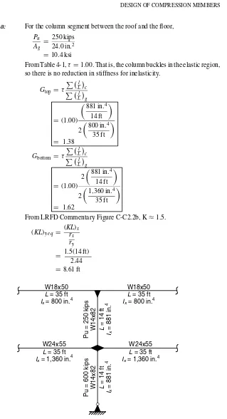
Fig. 4–1. Illustration for Example 4.2.
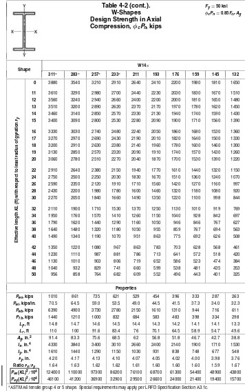
From Table 4-2,
φ
c
P
n
≈
898 kips
>
250 kips
o
.
k
.
For the column segment between the floor and the foundation,
P
u
G
bottom
=
10 (pinned end)
From LRFD Commentary Figure C-C2.2b, K
≈
2.0.
(
KL
)y eq
=
(
KL
r
)x
Thus, the W14
×
82 compression member is adequate.
Solution b:
As determined in solution a, for the column segment between the roof and
the floor,
φ
c
P
n
≈
898 kips
As determined in solution a, for the column segment between the floor
and the foundation,
G
top
=
1.38 and
G
bottom
=
1(fixed end)
From LRFD Commentary Figure C-C2.2b, K
≈
1.4.
Given:
Determine the design strength of an ASTM A36 L4
×
3
1
/
2
×
5
/
16
with
physical length
L
=
8 ft, pinned ends and no bracing along the length of
member. Also, calculate at what length this compression member would
cease to satisfy the slenderness limitation in Single-Angle Specification
Section 4.
F
y
=
36 ksi
A
g
=
2
.
25 in
.
2
F
u
=
58 ksi
r
z
=
0
.
721 in
.
Solution:
For L4
×
3
1
/
2
×
5
/
16
,
b
t
=
4 in
.
5
/
16
in
.
=
12
.
8
From Single-Angle Specification Section 4,
λ
p
=
0
.
446
E
F
y
=
0
.
446
29
,
000 ksi
36 ksi
=
12
.
7
λ
r
=
0
.
910
E
F
y
=
0
.
910
29
,
000 ksi
36 ksi
=
25
.
8
Since
λ
p
<
b
/
t
< λ
r
,
Q
=
1
.
34
−
0
.
761
b
t
F
y
E
=
1
.
34
−
0
.
761(12
.
8)
36 ksi
29
,
000 ksi
=
0
.
997
From LRFD Commentary Table C-C2.1,
K
=
1
.
0. From Single-Angle
Specification Section 4, using
r
=
r
z
(the least radius of gyration for the
cross-section),
λ
c
=
K l
r
π
F
y
E
=
1
.
0(8 ft
×
12 in
.
/ft)
(0
.
721 in
.
)
π
Table 4-2.
W-Shapes
Design Strength in Axial
Compression,
φ
cP
n, kips
Fy=50 ksiφcPn=0.85FcrAg
Shape W14×
808∗ 730∗ 665∗ 605∗ 550∗ 500∗ 455∗ 426∗ 398∗ 370∗ 342∗
0 10100 9140 8330 7570 6890 6250 5700 5310 4970 4630 4290
11 9540 8620 7850 7110 6460 5850 5330 4970 4640 4320 4000
12 9440 8530 7760 7030 6390 5780 5260 4900 4580 4260 3950
13 9330 8430 7660 6940 6300 5710 5190 4830 4520 4200 3890
14 9220 8320 7560 6850 6220 5620 5110 4760 4450 4140 3830
15 9100 8200 7450 6750 6120 5540 5030 4680 4380 4070 3760
16 8970 8080 7340 6640 6020 5450 4950 4600 4300 4000 3690
17 8840 7960 7220 6530 5920 5350 4860 4520 4220 3920 3620
18 8700 7820 7100 6420 5810 5250 4770 4430 4140 3840 3550
19 8550 7690 6970 6300 5700 5150 4670 4340 4050 3760 3470
20 8400 7550 6840 6170 5590 5040 4570 4250 3960 3680 3400
22 8090 7250 6560 5910 5350 4820 4370 4050 3780 3500 3230
24 7760 6940 6270 5640 5100 4590 4150 3850 3590 3320 3060
26 7410 6610 5970 5360 4840 4350 3930 3640 3390 3140 2890
28 7060 6280 5660 5080 4570 4100 3700 3430 3190 2950 2710
30 6700 5940 5340 4790 4300 3850 3480 3210 2990 2750 2530
32 6330 5600 5030 4490 4030 3610 3250 3000 2780 2560 2360
34 5970 5250 4710 4200 3760 3360 3020 2780 2580 2380 2180
36 5600 4910 4400 3910 3500 3120 2800 2570 2390 2190 2010
38 5240 4580 4090 3630 3240 2880 2580 2370 2190 2010 1840
40 4880 4250 3780 3350 2990 2650 2370 2170 2010 1840 1680
42 4530 3930 3490 3080 2740 2420 2160 1980 1830 1670 1530
44 4190 3620 3200 2820 2500 2210 1970 1800 1660 1520 1390
46 3860 3310 2930 2580 2290 2020 1800 1650 1520 1390 1270
48 3540 3040 2690 2370 2100 1860 1650 1510 1400 1280 1170
Eff
50 3260 2800 2480 2180 1940 1710 1520 1400 1290 1180 1080
Properties
Pwo, kips 5350 4230 3620 3090 2630 2240 1920 1710 1520 1350 1180
Pwi, kips/in. 187 154 142 130 119 110 101 94.0 88.5 83.0 77.0
Pwb, kips 119000 66100 51700 40100 30800 23900 18800 15100 12700 10400 8320
Pf b, kips 7370 6780 5750 4870 4100 3450 2900 2600 2280 1990 1720
Lp, ft 17.0 16.6 16.3 16.1 15.9 15.6 15.5 15.3 15.2 15.1 15.0
Lr, ft 268 242 222 203 188 171 158 147 139 130 121
Ag, in.2 237 215 196 178 162 147 134 125 117 109 101
Ix, in.4 16000 14300 12400 10800 9430 8210 7190 6600 6000 5440 4900
Iy, in.4 5510 4720 4170 3680 3250 2880 2560 2360 2170 1990 1810
ry, in. 4.82 4.69 4.62 4.55 4.49 4.43 4.38 4.34 4.31 4.27 4.24
Ratiorx/ry 1.70 1.74 1.73 1.71 1.70 1.69 1.67 1.67 1.66 1.66 1.65
Pex(KL)2/104 458000 409000 355000 309000 270000 235000 206000 189000 172000 156000 140000
Pey(KL)2/104 158000 135000 119000 105000 93000 82400 73300 67500 62100 57000 51800 ∗ASTM A6 tensile group 4 or 5 shape. Special requirements may apply per LRFD Specification Section A3.1c.
Shape W14×
311∗ 283∗ 257∗ 233∗ 211 193 176 159 145 132
0 3880 3540 3210 2910 2640 2410 2200 1980 1810 1650
11 3610 3290 2980 2700 2440 2230 2030 1830 1670 1510
12 3560 3240 2940 2660 2400 2200 2000 1810 1650 1480
13 3510 3200 2890 2620 2370 2170 1970 1780 1620 1450
14 3460 3140 2850 2570 2330 2130 1940 1740 1590 1430
15 3400 3090 2800 2530 2280 2090 1900 1710 1560 1390
16 3330 3030 2740 2480 2240 2050 1860 1680 1530 1360
17 3270 2970 2690 2430 2190 2010 1820 1640 1500 1330
18 3200 2910 2630 2380 2140 1960 1780 1600 1460 1300
19 3130 2850 2570 2320 2090 1910 1740 1570 1430 1260
20 3060 2780 2510 2270 2040 1870 1700 1530 1390 1220
22 2910 2640 2380 2150 1940 1770 1610 1440 1320 1150
24 2750 2500 2250 2030 1830 1670 1510 1360 1240 1070
26 2590 2350 2120 1910 1710 1560 1420 1270 1160 997
28 2430 2200 1980 1780 1600 1460 1320 1180 1080 920
30 2270 2050 1840 1660 1490 1350 1220 1100 998 844
32 2110 1900 1710 1530 1370 1250 1130 1010 919 769
34 1950 1760 1570 1410 1260 1150 1040 928 842 697
36 1790 1620 1440 1290 1160 1050 946 846 767 627
38 1640 1480 1320 1180 1050 955 859 767 694 563
40 1490 1340 1190 1070 951 863 775 692 626 508
42 1350 1220 1080 967 863 783 703 628 568 461
44 1230 1110 987 881 786 713 641 572 518 420
46 1130 1010 903 806 719 652 586 523 474 384
48 1040 932 829 741 660 599 538 481 435 353
Eff
ective
length
KL
(ft)
with
respect
to
least
radius
of
gyration
ry
50 956 858 764 682 609 552 496 443 401 325
Properties
Pwo, kips 1010 861 735 621 529 454 396 333 287 263
Pwi, kips/in. 70.5 64.5 59.0 53.5 49.0 44.5 41.5 37.3 34.0 32.3
Pwb, kips 6390 4900 3730 2780 2150 1610 1310 944 716 611
Pf b, kips 1440 1210 1000 832 684 583 483 398 334 298
Lp, ft 14.8 14.7 14.6 14.5 14.4 14.3 14.2 14.1 14.1 13.3
Lr, ft 110 100 91.6 83.4 76 70.1 64.5 58.9 54.7 49.6
Ag, in.2 91.4 83.3 75.6 68.5 62 56.8 51.8 46.7 42.7 38.8
Ix, in.4 4330 3840 3400 3010 2660 2400 2140 1900 1710 1530
Iy, in.4 1610 1440 1290 1150 1030 931 838 748 677 548
ry, in. 4.20 4.17 4.13 4.10 4.07 4.05 4.02 4.00 3.98 3.76
Ratiorx/ry 1.64 1.63 1.62 1.62 1.61 1.60 1.60 1.60 1.59 1.67
Pex(KL)2/104 124000 110000 97300 86200 76100 68700 61300 54400 48900 43800
Pey(KL)2/104 46100 41200 36900 32900 29500 26600 24000 21400 19400 15700 ∗ASTM A6 tensile group 4 or 5 shape. Special requirements may apply per LRFD Specification Section A3.1c.
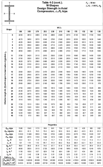
Table 4-2 (cont.).
W-Shapes
Design Strength in Axial
Compression,
φ
cP
n, kips
0 1500 1360 1240 1130 1020 927 850 761 663 599 530
6 1460 1320 1200 1100 959 871 798 714 598 540 482
7 1450 1310 1190 1080 938 852 781 698 576 520 463
8 1430 1300 1180 1070 914 830 760 680 552 498 443
9 1410 1280 1160 1060 888 807 738 660 526 474 422
10 1390 1260 1150 1040 860 781 714 638 498 449 399
11 1370 1240 1130 1030 829 753 689 615 469 423 375
12 1350 1220 1110 1010 797 724 662 591 439 395 350
13 1320 1200 1090 989 764 694 633 566 409 368 325
14 1290 1170 1060 969 729 662 604 539 379 340 301
15 1270 1150 1040 947 694 630 575 513 349 313 276
16 1240 1120 1020 925 658 598 544 486 319 286 252
17 1210 1090 991 902 622 565 514 458 290 260 228
18 1180 1060 965 878 586 532 484 431 263 235 206
19 1140 1030 938 853 550 499 454 404 236 211 185
20 1110 1000 911 828 514 467 424 377 213 191 167
22 1040 943 854 776 445 405 366 325 176 157 138
24 972 879 796 723 380 345 311 276 148 132 116
Pex(KL)2/104 39500 35500 31800 28600 25200 22800 20700 18300 15500 13900 12300
Pey(KL)2/104 14200 12800 11500 10400 4240 3840 3460 3060 1650 1470 1290
††For W14
×99 and W14×90, flange is non-compact. For W14×43, web may be non-compact for combined axial compression and flexure; see AISC LRFD Specification Section B5.
Note: Heavy line indicatesKl/requal to or greater than 200.
Rev.
Shape W12 ×
336 305 279 252 230 210 190 170 152 136 120
0 4200 3810 3480 3150 2880 2630 2370 2130 1900 1700 1500
6 4070 3690 3370 3040 2780 2540 2290 2050 1830 1630 1440
7 4020 3640 3330 3000 2740 2500 2260 2020 1810 1610 1420
8 3970 3590 3280 2960 2710 2470 2220 1990 1780 1590 1400
9 3910 3540 3230 2910 2660 2430 2190 1960 1750 1560 1380
10 3850 3480 3170 2860 2610 2380 2150 1920 1710 1530 1350
11 3780 3420 3110 2810 2560 2330 2100 1880 1680 1490 1320
12 3700 3350 3050 2750 2510 2280 2050 1840 1640 1460 1290
13 3620 3270 2980 2680 2450 2230 2000 1790 1590 1420 1250
14 3540 3190 2910 2610 2380 2170 1950 1740 1550 1380 1220
15 3450 3110 2830 2540 2320 2110 1900 1690 1510 1340 1180
16 3360 3020 2750 2470 2250 2040 1840 1640 1460 1290 1140
17 3260 2940 2670 2390 2180 1980 1780 1580 1410 1250 1100
18 3160 2840 2580 2320 2110 1910 1720 1530 1360 1210 1060
19 3060 2750 2500 2240 2030 1840 1650 1470 1310 1160 1020
20 2960 2660 2410 2160 1960 1780 1590 1420 1260 1110 976
22 2750 2460 2230 1990 1810 1640 1460 1300 1150 1020 892
24 2540 2270 2050 1830 1650 1490 1340 1180 1050 924 808
26 2330 2070 1870 1660 1500 1360 1210 1070 944 831 726
28 2120 1880 1690 1500 1350 1220 1090 959 844 742 646
30 1910 1690 1520 1340 1210 1090 967 852 749 656 569
32 1720 1510 1350 1190 1070 962 853 750 658 577 500
34 1520 1340 1200 1060 951 852 755 664 583 511 443
36 1360 1200 1070 944 848 760 674 593 520 456 395
38 1220 1080 960 847 761 682 605 532 467 409 355
Eff
ective
length
KL
(ft)
with
respect
to
least
radius
of
gyration
ry
40 1100 970 866 764 687 616 546 480 421 369 320
Properties
Pwo, kips 1580 1340 1170 998 861 738 617 518 435 365 302
Pwi, kips/in. 89.0 81.5 76.5 70.0 64.5 59.0 53.0 48.0 43.5 39.5 35.5
Pwb, kips 15100 11600 9590 7320 5730 4400 3190 2370 1760 1320 957
Pf b, kips 2460 2070 1720 1420 1210 1020 852 684 551 439 347
Lp, ft 12.3 12.1 11.9 11.8 11.7 11.6 11.5 11.4 11.3 11.2 11.1
Lr, ft 131 119 110 99.7 91.9 84.2 76.6 68.9 62.1 55.7 50.0
Ag, in.2 98.8 89.6 81.9 74.0 67.7 61.8 55.8 50.0 44.7 39.9 35.3
Ix, in.4 4060 3550 3110 2720 2420 2140 1890 1650 1430 1240 1070
Iy, in.4 1190 1050 937 828 742 664 589 517 454 398 345
ry, in. 3.47 3.42 3.38 3.34 3.31 3.28 3.25 3.22 3.19 3.16 3.13
Ratiorx/ry 1.85 1.84 1.82 1.81 1.80 1.80 1.79 1.78 1.77 1.77 1.76
Pex(KL)2/104 116000 102000 89000 77900 69300 61300 54100 47200 40900 35500 30600 Pey(KL)2/104 34100 30100 26800 23700 21200 19000 16900 14800 13000 11400 9870
Rev.
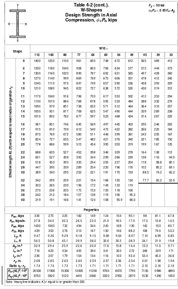
Table 4-2 (cont.).
W-Shapes
Design Strength in Axial
Compression,
φ
cP
n, kips
0 1330 1200 1090 986 897 812 723 663 621 557 497
6 1280 1150 1050 947 861 779 680 623 562 504 450
7 1260 1140 1030 933 848 767 666 610 543 486 434
8 1240 1120 1010 917 834 754 649 594 521 466 416
9 1210 1100 994 900 818 739 631 577 497 445 396
10 1190 1070 973 880 800 723 611 559 472 422 376
11 1160 1050 950 860 781 706 590 539 445 398 354
12 1130 1020 926 838 761 687 568 518 418 374 332
13 1100 995 901 814 740 668 545 496 390 349 310
14 1070 966 874 790 717 647 521 474 363 324 287
15 1040 935 846 764 694 626 496 451 335 299 265
16 1000 904 817 738 670 604 471 428 308 274 243
17 968 871 788 711 645 581 446 404 281 250 222
Pex(KL)2/104 26700 23800 21200 18900 17100 15300 13600 12200 11200 9960 8790
Pey(KL)2/104 8620 7730 6900 6180 5580 4980 3060 2740 1610 1430 1260 ††Flange is non-compact.
Note: Heavy line indicatesKl/requal to or greater than 200.
Rev.
Shape W10 ×
112 100 88 77 68 60 54 49 45 39 33
0 1400 1250 1100 961 850 748 672 612 565 489 413
6 1330 1180 1040 908 803 706 634 577 515 444 373
7 1300 1160 1020 890 787 692 621 565 497 428 360
8 1270 1140 999 869 769 675 606 551 478 412 345
9 1240 1110 973 847 749 657 590 536 458 393 329
10 1210 1080 945 822 727 638 572 520 436 374 312
11 1170 1040 916 796 703 617 553 502 412 353 294
12 1130 1010 884 768 678 595 533 484 388 332 276
13 1090 970 851 738 652 571 512 464 364 310 257
14 1050 931 817 708 625 547 490 444 339 289 238
15 1010 892 782 677 597 523 468 424 314 267 220
16 961 851 746 645 569 497 445 403 290 246 202
17 915 810 709 612 540 472 422 382 266 225 184
18 870 769 672 580 511 446 399 361 243 205 167
19 824 727 635 547 482 421 376 340 221 185 150
20 778 686 599 515 454 395 353 319 199 167 135
22 688 605 527 452 398 346 309 278 164 138 112
24 601 527 458 392 344 299 266 239 138 116 94.0
26 518 453 393 335 294 255 227 204 118 98.8 80.1
28 447 390 339 289 254 220 196 176 102 85.2 69.1
30 389 340 295 252 221 191 170 153 88.5 74.2 60.2
32 342 299 259 221 194 168 150 134 77.7 65.2 52.9
34 303 265 230 196 172 149 133 119
36 270 236 205 175 153 133 118 106
38 242 212 184 157 138 119 106 95.3
Eff
ective
length
KL
(ft)
with
respect
to
least
radius
of
gyration
ry
40 219 191 166 141 124 108 95.9 86.0
Properties
Pwo, kips 330 275 225 182 149 124 104 90.1 98 81.1 67.8
Pwi, kips/in. 37.8 34.0 30.3 26.5 23.5 21.0 18.5 17.0 17.5 15.8 14.5
Pwb, kips 1430 1040 732 494 344 245 168 130 142 103 80.7
Pf b, kips 439 353 276 213 167 130 106 88.2 108 79.0 53.2
Lp, ft 9.47 9.36 9.29 9.18 9.15 9.08 9.04 8.97 7.10 6.99 6.85
Lr, ft 56.5 50.8 45.1 39.9 36.0 32.6 30.2 28.3 24.1 21.9 19.8
Ag, in.2 32.9 29.4 25.9 22.6 20.0 17.6 15.8 14.4 13.3 11.5 9.71
Ix, in.4 716 623 534 455 394 341 303 272 248 209 171
Iy, in.4 236 207 179 154 134 116 103 93.4 53.4 45.0 36.6
ry, in. 2.68 2.65 2.63 2.60 2.59 2.57 2.56 2.54 2.01 1.98 1.94
Ratiorx/ry 1.74 1.74 1.73 1.73 1.71 1.71 1.71 1.71 2.15 2.16 2.16
Pex(KL)2/104 20500 17800 15300 13000 11300 9760 8670 7790 7100 5980 4890 Pey(KL)2/104 6750 5920 5120 4410 3840 3320 2950 2670 1530 1290 1050 Note: Heavy line indicatesKl/requal to or greater than 200.
Table 4-3.
HP-Shapes
Design Strength in Axial
Compression,
φ
cP
n, kips
Pex(KL)2/104 34900 30100 25900 20900 18600 16300 13500 11200 8410 6010 3410 Pey(KL)2/104 12700 10900 9330 7470 6100 5320 4380 3630 2890 2050 1150 ††Flange is non-compact.
Note: Heavy line indicatesKl/requal to or greater than 200.
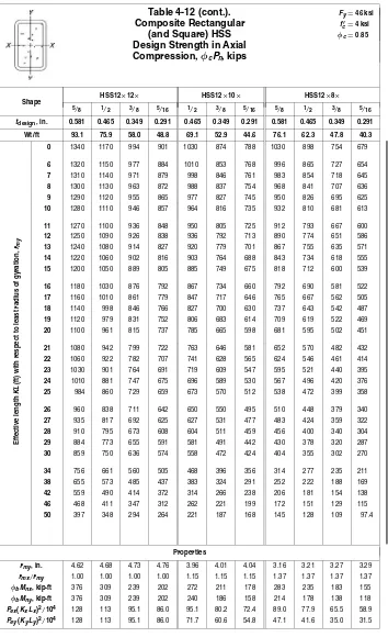
Shape HSS12
×12× HSS12×10× HSS12×8×
5/8 1/2 3/8 5/16 1/2 3/8 5/16 5/8 1/2 3/8 5/16
tdesign, in. 0.581 0.465 0.349 0.291 0.465 0.349 0.291 0.581 0.465 0.349 0.291
Wt/ft 93.1 75.9 58.0 48.8 69.1 52.9 44.6 76.1 62.3 47.8 40.3
0 1340 1170 994 901 1030 874 788 1030 898 754 679
6 1320 1150 977 884 1010 853 768 996 865 727 654
7 1310 1140 971 879 998 846 761 983 854 718 645
8 1300 1130 963 872 988 837 754 968 841 707 636
9 1290 1120 955 865 977 827 745 950 826 695 625
10 1280 1110 946 857 964 816 735 932 810 681 613
11 1270 1100 936 848 950 805 725 912 793 667 600
12 1250 1090 926 838 936 792 713 890 774 651 586
13 1240 1080 914 827 920 779 701 867 755 635 571
14 1220 1060 902 816 903 764 688 843 734 618 555
15 1200 1050 889 805 885 749 675 818 712 600 539
16 1180 1030 876 792 867 734 660 792 690 581 522
17 1160 1010 861 779 847 717 646 765 667 562 505
18 1140 998 846 766 827 700 630 737 643 542 487
19 1120 979 831 752 806 683 614 709 619 522 469
20 1100 961 815 737 785 665 598 681 595 502 451
21 1080 942 799 722 763 646 581 652 570 482 432
22 1060 922 782 707 741 628 565 624 546 461 414
23 1030 901 764 691 719 609 547 595 521 440 395
24 1010 881 747 675 696 589 530 567 496 420 376
25 984 860 729 659 673 570 512 538 472 399 358
26 960 838 711 642 650 550 495 510 448 379 340
27 935 817 692 625 627 531 477 483 424 359 322
28 910 795 673 608 604 511 459 456 400 340 304
29 884 773 655 591 581 491 442 430 378 320 287
30 859 750 636 574 558 472 424 404 355 302 270
34 756 661 560 505 468 396 356 314 277 235 211
38 655 573 485 437 383 324 291 252 222 188 169
42 559 490 414 372 314 266 238 206 181 154 138
46 468 411 347 312 262 221 199 172 151 129 115
Eff
ective
length
KL
(ft)
with
respect
to
least
radius
of
gyration,
rmy
50 397 348 294 264 221 187 168 145 128 109 97.4
Properties
rmy, in. 4.62 4.68 4.73 4.76 3.96 4.01 4.04 3.16 3.21 3.27 3.29
rmx/rmy 1.00 1.00 1.00 1.00 1.15 1.15 1.15 1.37 1.37 1.37 1.37
φbMnx, kip-ft 376 309 239 202 272 211 178 283 235 183 155
φbMn y, kip-ft 376 309 239 202 240 186 158 214 178 138 118
Pex(KxLx)2/104 128 113 95.1 86.0 95.1 80.2 72.4 89.0 77.9 65.5 58.9
Pey(KyLy)2/104 128 113 95.1 86.0 71.7 60.6 54.8 47.1 41.6 35.0 31.5
Table 4-12 (cont.).
Composite Rectangular
(and Square) HSS
Design Strength in Axial
Compression,
φ
cP
n, kips
tdesign, in. 0.581 0.465 0.349 0.291 0.581 0.465 0.349 0.291 0.233
Wt/ft 67.6 55.5 42.7 36.0 76.1 62.3 47.8 40.3 32.6
0 882 760 634 566 1050 910 766 690 613
Note: Heavy line indicatesKl/requal to or greater than 200.
Shape HSS10
×8× HSS10×6× HSS10×5×
1/2 3/8 5/16 1/4 5/8 1/2 3/8 5/16 1/4 3/8 5/16 1/4
tdesign, in. 0.465 0.349 0.291 0.233 0.581 0.465 0.349 0.291 0.233 0.349 0.291 0.233
Wt/ft 55.5 42.7 36.0 29.2 59.1 48.7 37.6 31.8 25.8 35.1 29.7 24.1
0 783 657 590 521 764 660 549 490 430 493 439 384
6 753 633 567 502 714 618 515 459 403 451 402 351
7 743 624 560 495 697 604 503 449 394 436 389 340
8 731 614 551 487 678 588 490 437 384 420 375 328
9 718 603 541 478 656 570 475 424 372 403 359 314
10 704 591 530 469 633 550 459 410 360 384 342 300
11 688 578 519 458 609 530 442 395 347 364 325 285
12 671 564 506 447 583 508 424 379 333 344 307 269
13 653 549 493 436 557 485 406 363 318 323 288 253
14 635 534 479 423 529 462 387 346 303 302 269 236
15 615 518 464 410 501 438 367 329 288 281 251 220
16 595 501 449 397 473 414 347 311 272 260 232 204
17 575 484 434 383 445 390 327 293 257 239 213 188
18 554 466 418 369 416 366 307 276 241 219 196 172
19 532 448 402 355 388 342 288 258 226 199 178 157
20 510 430 386 341 361 318 268 241 211 180 161 142
21 488 412 369 326 334 295 249 224 196 164 146 129
22 466 393 353 311 308 273 231 208 181 149 133 118
23 444 375 336 297 283 251 213 192 167 136 122 108
24 423 357 320 282 260 231 196 176 154 125 112 98.8
25 401 338 304 268 239 213 180 162 142 115 103 91.1
26 380 321 288 254 221 197 167 150 131 107 95.5 84.2
27 359 303 272 240 205 182 155 139 121 99.0 88.6 78.1
28 338 286 257 226 191 170 144 129 113 92.1 82.4 72.6
29 318 269 242 213 178 158 134 121 105 85.8 76.8 67.7
30 298 252 227 200 166 148 125 113 98.4 80.2 71.7 63.2
32 262 222 199 176 146 130 110 99.0 86.5 70.5 63.1 55.6
34 232 197 177 156 129 115 97.5 87.7 76.6 62.4 55.9 49.2
36 207 175 157 139 115 103 86.9 78.2 68.3
38 186 157 141 125 104 92.1 78.0 70.2 61.3
Eff
ective
length
KL
(ft)
with
respect
to
least
radius
of
gyration,
rmy
40 168 142 128 112 70.4 63.4 55.3
Properties
rmy, in. 3.14 3.19 3.22 3.25 2.34 2.39 2.44 2.47 2.49 2.05 2.07 2.10
rmx/rmy 1.19 1.19 1.19 1.18 1.50 1.49 1.49 1.48 1.48 1.72 1.72 1.71
φbMnx, kip-ft 179 140 119 96.9 177 148 117 99.4 81.4 105 89.7 73.5
φbMn y, kip-ft 154 120 102 83.5 124 104 81.8 69.7 57.3 64.5 55.2 45.5
Pex(KxLx)2/104 49.3 41.4 37.3 32.8 43.4 38.2 32.3 29.0 25.3 27.6 24.8 21.6 Pey(KyLy)2/104 34.8 29.4 26.5 23.3 19.3 17.1 14.6 13.1 11.5 9.33 8.41 7.39 Note: Heavy line indicatesKl/requal to or greater than 200.
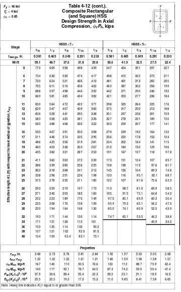
Table 4-12 (cont.).
Composite Rectangular
(and Square) HSS
Design Strength in Axial
Compression,
φ
cP
n, kips
tdesign, in. 0.581 0.465 0.349 0.291 0.233 0.581 0.465 0.349 0.291 0.233
Wt/ft 59.1 48.7 37.6 31.8 25.8 50.6 41.9 32.5 27.5 22.4
0 773 669 558 498 439 547 454 351 297 227 Note: Heavy line indicatesKl/requal to or greater than 200.
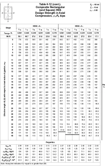
Shape HSS8
×8× HSS8×6×
5/8 1/2 3/8 5/16 1/4 3/16 5/8 1/2 3/8 5/16 1/4 3/16
tdesign, in. 0.581 0.465 0.349 0.291 0.233 0.174 0.581 0.465 0.349 0.291 0.233 0.174
Wt/ft 59.1 48.7 37.6 31.8 25.8 19.6 50.6 41.9 32.5 27.5 22.4 17.1
0 776 672 560 501 442 379 642 557 462 413 362 308
6 744 645 538 482 424 364 598 519 432 386 338 288
7 733 636 531 475 418 359 583 507 422 377 330 281
8 720 625 522 467 411 353 566 492 410 366 321 273
9 706 613 512 458 403 346 547 476 397 355 311 264
10 691 600 501 449 395 338 527 459 384 343 300 255
11 675 586 490 438 386 330 505 441 369 329 289 245
12 657 571 477 427 376 322 483 422 353 316 277 235
13 638 555 464 415 365 313 459 402 337 301 264 224
14 619 538 450 403 354 304 435 382 321 286 251 213
15 598 521 436 390 343 294 411 361 304 271 238 202
16 577 503 421 377 331 284 387 340 287 256 225 191
17 556 484 406 364 319 273 362 319 270 241 212 179
18 534 465 391 350 307 263 338 298 252 226 198 168
19 511 446 375 336 295 252 314 278 236 211 185 157
20 489 427 359 321 282 241 291 258 219 196 172 146
21 466 408 343 307 269 230 268 238 203 181 160 135
22 444 388 327 293 257 219 246 219 187 167 147 125
23 421 369 311 278 244 208 225 201 172 154 135 114
24 399 350 295 264 231 197 207 184 158 141 124 105
25 377 331 279 250 219 187 190 170 145 130 114 96.9
26 356 312 264 237 207 176 176 157 134 120 106 89.6
27 335 294 249 223 195 166 163 146 125 111 98.1 83.0
28 314 276 234 210 183 156 152 135 116 104 31.2 77.2
29 294 259 220 197 172 146 141 126 108 96.6 85.1 72.0
30 274 242 205 184 161 136 132 118 101 90.3 79.5 67.3
32 241 213 180 162 141 120 116 104 88.8 79.4 69.9 59.1
34 214 188 160 143 125 106 103 91.9 78.6 70.3 61.9 52.4
36 191 168 142 128 112 94.7 91.8 82.0 70.1 62.7 55.2 46.7
38 171 151 128 115 100 85.0 73.6 62.9 56.3 49.5 41.9
Eff
ective
length
KL
(ft)
with
respect
to
least
radius
of
gyration,
rmy
40 154 136 115 103 90.3 76.7 50.8 44.7 37.8
Properties
rmy, in. 2.99 3.04 3.10 3.13 3.15 3.18 2.27 2.32 2.38 2.40 2.43 2.46
rmx/rmy 1.00 1.00 1.00 1.00 1.00 1.00 1.26 1.25 1.25 1.25 1.25 1.24
φbMnx, kip-ft 154 129 101 86.6 70.7 54.2 125 105 83.1 71.1 58.3 44.9
φbMn y, kip-ft 154 129 101 86.6 70.7 54.2 102 85.9 68.3 58.3 48.0 36.9
Pex(KxLx)2/104 31.9 28.2 23.8 21.4 18.8 16.0 24.4 21.6 18.3 16.4 14.4 12.2 Pey(KyLy)2/104 31.9 28.2 23.8 21.4 18.8 16.0 15.5 13.8 11.7 10.5 9.27 7.85 Note: Heavy line indicatesKl/requal to or greater than 200.
Table 4-12 (cont.).
Composite Rectangular
(and Square) HSS
Design Strength in Axial
Compression,
φ
cP
n, kips
tdesign, in. 0.581 0.465 0.349 0.291 0.233 0.174 0.581 0.465 0.349 0.291 0.233 0.174
Wt/ft 42.1 35.1 27.4 23.3 19.0 14.5 50.6 41.9 32.5 27.5 22.4 17.1
0 513 443 366 324 282 236 645 560 465 416 364 310
Note: Heavy line indicatesKl/requal to or greater than 200.
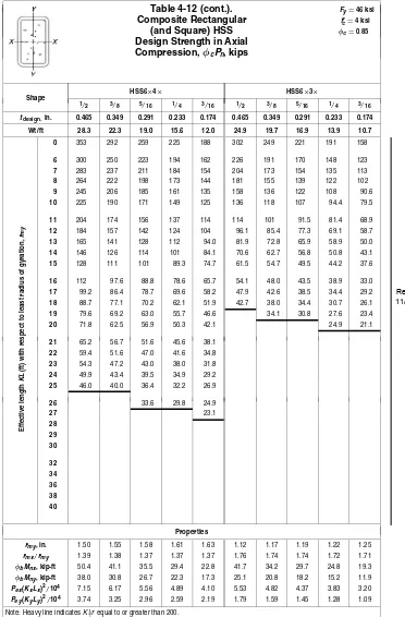
Shape HSS7
×5× HSS7×4×
5/8 1/2 3/8 5/16 1/4 3/16 1/2 3/8 5/16 1/4 3/16
tdesign, in. 0.581 0.465 0.349 0.291 0.233 0.174 0.465 0.349 0.291 0.233 0.174
Wt/ft 42.1 35.1 27.4 23.3 19.0 14.5 31.7 24.9 21.2 17.3 13.2
0 521 452 374 333 290 245 398 329 292 253 212
6 469 408 340 303 264 223 340 283 252 219 184
7 452 394 328 292 255 215 322 268 239 208 175
8 432 377 315 281 245 207 301 252 225 196 164
9 411 360 301 268 234 198 280 235 210 184 154
10 389 341 286 255 223 188 258 217 195 170 143
11 366 322 270 241 211 178 235 199 179 157 131
12 342 301 254 227 198 167 213 181 163 143 120
13 318 281 238 212 186 157 191 163 147 130 108
14 294 260 221 197 173 146 170 146 132 116 97.3
15 270 240 204 183 160 135 150 129 118 104 86.7
16 247 220 188 168 148 125 131 114 104 91.5 76.5
17 224 201 172 154 135 114 116 101 91.7 81.1 67.8
18 202 182 157 140 123 104 104 89.9 81.8 72.3 60.5
19 181 164 141 127 112 94.3 93.2 80.7 73.4 64.9 54.3
20 164 148 128 114 101 85.1 84.1 72.8 66.3 58.6 49.0
21 148 134 116 104 91.4 77.2 76.3 66.1 60.1 53.1 44.4
22 135 122 106 94.5 83.3 70.4 69.5 60.2 54.8 48.4 40.5
23 124 112 96.5 86.4 76.2 64.4 63.6 55.1 50.1 44.3 37.0
24 114 102 88.7 79.4 70.0 59.1 58.4 50.6 46.0 40.7 34.0
25 105 94.5 81.7 73.2 64.5 54.5 53.8 46.6 42.4 37.5 31.3
26 96.8 87.3 75.5 67.6 59.6 50.4 43.1 39.2 34.7 29.0
27 89.8 81.0 70.1 62.7 55.3 46.7 32.1 26.9
28 83.5 75.3 65.1 58.3 51.4 43.4
29 77.8 70.2 60.7 54.4 47.9 40.5
30 72.7 65.6 56.7 50.8 44.8 37.8
32 49.9 44.7 39.3 33.3
34 29.5
36 38
Eff
ective
length
KL
(ft)
with
respect
to
least
radius
of
gyration,
rmy
40
Properties
rmy, in. 1.86 1.91 1.97 1.99 2.02 2.05 1.53 1.58 1.61 1.64 1.66
rmx/rmy 1.31 1.31 1.30 1.30 1.30 1.29 1.57 1.56 1.55 1.54 1.54
φbMnx, kip-ft 88.3 75.6 60.4 51.8 42.8 32.8 64.9 52.1 45.2 37.3 28.7
φbMn y, kip-ft 69.7 59.7 47.6 41.1 33.9 26.1 43.5 35.2 30.5 25.3 19.6
Pex(KxLx)2/104 14.6 13.0 11.1 10.00 8.77 7.37 10.7 9.18 8.26 7.21 6.04
Pey(KyLy)2/104 8.52 7.66 6.59 5.93 5.20 4.39 4.38 3.80 3.44 3.03 2.54
Note: Heavy line indicatesKl/requal to or greater than 200.
Table 4-12 (cont.).
Composite Rectangular
(and Square) HSS
Design Strength in Axial
Compression,
φ
cP
n, kips
tdesign, in. 0.581 0.465 0.349 0.291 0.233 0.174 0.349 0.291 0.233 0.174
Wt/ft 42.1 35.1 27.4 23.3 19.0 14.5 24.9 21.2 17.3 13.2
0 524 455 377 336 293 248 335 298 259 218 Note: Heavy line indicatesKl/requal to or greater than 200.