U.S. Department Publication No. FHWA HI-98-032
of Transportation May 2001
Federal Highway Administration
NHI Course No. 132068
) ) ) ) ) ) ) ) ) ) ) ) ) ) ) ) ) ) ) ) ) ) ) ) ) ) ) ) ) ) ) ) ) ) ) ) ) ) ) ) ) ) ) ) ) ) ) ) ) ) ) ) ) ) ) ) ) ) ) ) ) ) ) ) ) ) ) ) ) ) ) ) ) ) ) ) ) ) ) ) ) ) ) ) ) ) ) ) ) ) ) ) ) ) ) ) ) ) ) ) ) ) ) ) ) ) ) ) ) )
Load and Resistance Factor Design (LRFD)
for Highway Bridge Substructures
Reference Manual and Participant Workbook
PREFACE
For many years, engineers have designed foundations, walls and culverts for highway and other applications using allowable stress design (ASD) methods. In ASD, all uncertainty in loads and material resistance is combined in a factor of safety or allowable stress. For most highway design, the American Association of State Highway and Transportation Officials (AASHTO) Standard Specifications for Highway Bridges represents the primary source document for ASD of substructures. In 1994, AASHTO approved Load and Resistance Factor Design (LRFD) in the LRFD Highway Bridge Design Specifications. In LRFD, the uncertainty in load is represented by a load factor and the uncertainty in material resistance is represented by a resistance factor. Due to the fundamental differences between the substructure design process by ASD and LRFD, this course has been developed to present the fundamentals of LRFD for the geotechnical design of highway bridge substructures. Because this document was prepared for engineers and others who are already familiar with the design of substructures using ASD, it is intended for use in conjunction with other documents describing standard geotechnical design procedures.
The objectives of this reference manual are to provide the basis for an understanding of the:
• Differences between ASD and LRFD for substructure design
• Benefits of LRFD for substructure design
• Importance of site characterization and selection of geotechnical design parameters
• Process for design of substructure elements by LRFD using the AASHTO LRFD Specifications as a guide
• Process for selection and application of load factors and load combinations
• Methods available for calibration of resistance factors
• Basis for calibration of the AASHTO LRFD resistance factors for substructure design
• Procedures available for modifying or developing resistance factors to achieve designs comparable to ASD
This Reference Manual is intended principally to serve as a supplement to the Participant’s Workbook for the FHWA’s National Highway Institute Course on Load and Resistance Factor Design for Highway Bridge Substructures. The Reference Manual can also serve as a primary reference for engineers in modifying or developing resistance factors to achieve designs comparable to ASD and for designing foundations, earth retaining structures and culverts through the numerous design examples included throughout the design chapters in the manual.
The authors also wish to acknowledge contributions of the following members of the Technical Working Group listed in alphabetical order:
• Chris Benda - Vermont Department of Transportation
• James Cuthbertson - Washington State Department of Transportation
• Richard Engle - Ohio Department of Transportation
• Ashton Lawler - Virginia Department of Transportation
• James Lyons - Federal Highway Administration
• Paul Passe - Florida Department of Transportation
• Tom Saad - Federal Highway Administration
• James Schluter - CONTECH Construction Products
TABLE OF CONTENTS
LIST OF TABLES xii
LIST OF FIGURES xix
LIST OF SYMBOLS xxiii
CHAPTER 1 - INTRODUCTION
1.1 Manual Objectives ... 1-1 1.2 Manual Outline ... 1-2 1.3 General References ... 1-3
CHAPTER 2 - TRANSITION TO LRFD FOR SUSBSTRUCTURE DESIGN
2.1 Introduction... 2-1 2.2 Allowable Stress Design ... 2-1 2.3 Load and Resistance Factor Design... 2-2 2.4 LRFD Calibration ... 2-8 2.5 Summary ... 2-9
CHAPTER 3 PRINCIPLES OF LIMIT STATES DESIGN
3.1 Introduction... 3-1 3.2 Design Procedures ... 3-2 3.2.1 Allowable Stress Design (ASD) ... 3-2 3.2.2 Shortcomings of ASD ... 3-3 3.2.3 Load and Resistance Factor Design (LRFD) ... 3-4 3.2.4 Advantages and Limitations of LRFD... 3-5 3.3 Calibration... 3-6 3.4 Review of Statistics and Probability Concepts ... 3-10
3.4.1 Statistical Descriptors ... 3-10 3.4.2 Probability Density Functions... 3-12 3.4.3 Probability of Failure ... 3-16 3.4.4 Reliability Index, $... 3-17 3.4.5 Resistance Statistics ... 3-20 3.4.6 Load Statistics... 3-23 3.4.7 Calibration by a Combined Approach ... 3-29 3.5 Student Exercise... 3-31
CHAPTER 4 - LOADS
4.1 Introduction... 4-1 4.2 Load Considerations for Geotechnical Design of Substructures ... 4-2
TABLE OF CONTENTS (continued)
4.2.2.1 Vehicular Live Load - LL ... 4-9 4.2.2.2 Vehicular Dynamic Load Allowance - IM... 4-10 4.2.2.3 Vehicular Centrifugal Force - CE ... 4-10 4.2.2.4 Vehicular Breaking Force - BR... 4-10 4.2.2.5 Pedestrian Live Load - PL... 4-11 4.2.2.6 Live Load Surcharge - LS ... 4-11 4.2.2.7 Water Load and Stream Pressure Force - WA ... 4-12 4.2.2.8 Wind Load - WS and WL... 4-13 4.2.2.9 Friction Force- FR ... 4-14 4.2.2.10 Force Effects Due to Superimposed Deformations - TU, TG,
CR, SH, and SE... 4-15 4.2.2.11 Earthquake Force - EQ ... 4-15 4.2.2.12 Ice Load - IC... 4-21 4.2.2.13 Vehicular Collision Force - CT ... 4-23 4.2.2.14 Vessel Collision Force - CV... 4-23 4.3 Load Factors and Load Combinations ... 4-24 4.4 Loads on Foundations and Retaining Walls ... 4-31 4.5 Loads on Culverts ... 4-34 4.5.1 Earth Loads ... 4-34 4.5.2 Vehicular Live Loads... 4-36 4.6 Student Exercise... 4-47 4.7 Student Problem: Load Combinations for Retaining Wall ... 4-48 4.8 Design Example: Load Combinations for Bridge Pier Foundation ... 4-57
CHAPTER 5 - GEOTECHNICAL SITE CHARACTERIZATION
5.1 Introduction... 5-1 5.2 Planning Exploration and Testing Programs ... 5-1 5.2.1 General... 5-1 5.2.2 Soil and Rock Variability... 5-2 5.3 Field Test Methods ... 5-8
5.3.1 Split-Barrel Sampling ... 5-9 5.3.2 Cone Penetration Testing... 5-10 5.3.3 Vane Shear Testing ... 5-12 5.3.4 Pressuremeter Test ... 5-13 5.3.5 Other Methods ... 5-14 5.3.5.1 Undisturbed Sampling ... 5-15 5.3.5.2 Rock Coring ... 5-16 5.3.5.3 Ground Water Location ... 5-16 5.4 Laboratory Test Methods ... 5-16
TABLE OF CONTENTS (continued)
5.5 Local Geologic Problem Conditions... 5-21 5.6 Example Problem: Develop Site Specific Resistance Factors from Field and
Laboratory Test Data ... 5-23
CHAPTER 6 - GEOTECHNICAL DESIGN PARAMETER SELECTION
6.1 Introduction... 6-1 6.2 Test Method Selection ... 6-1
6.2.1 Field Test Methods ... 6-2 6.2.1.1 Shear Strength... 6-2 6.2.1.2 Compressibility ... 6-4 6.2.2 Laboratory Tests ... 6-5 6.2.2.1 Shear Strength... 6-5 6.2.2.2 Compressibility ... 6-5 6.2.2.3 Index Tests ... 6-5 6.2.3 Parameter Evaluation ... 6-6 6.3 Reliability of Tests for Estimating Design Parameters... 6-7
6.3.1 Field Test Methods ... 6-7 6.3.1.1 Shear Strength... 6-7 6.3.1.1.1 Effective Stress Strength... 6-7 6.3.1.1.2 Total Stress Strength ... 6-9 6.3.1.2 Compressibility ... 6-11 6.3.2 Laboratory Tests ... 6-14 6.4 Design Parameter Selection and Resistance Factors ... 6-16 6.5 Example Problem: Characterization Planning ... 6-18
CHAPTER 7 - CALIBRATION AS PART OF THE DESIGN PROCESS
TABLE OF CONTENTS (continued)
7.7 Student Exercise... 7-14 Appendix 7A - Derivation of Simplified Reliability Calibration of Resistance Factors ... 7-15 Appendix 7B - Derivation for Fitting with ASD ... 7-17
CHAPTER 8 - SPREAD FOOTING DESIGN
8.1 Introduction... 8-1 8.2 Design Methods ... 8-1
8.2.1 ASD Summary ... 8-1 8.2.2 LRFD Summary... 8-5 8.2.2.1 Limit States ... 8-7 8.2.2.2 Resistance Factors... 8-8 8.2.2.3 Comparison of Spread Footing Design Using LRFD and ASD ... 8-10 8.2.2.4 Modification of Resistance Factors ... 8-13 8.2.3 Summarized Comparison of ASD and LRFD ... 8-14 8.3 Performance Limits... 8-14 8.3.1 Displacements and Tolerable Movement Criteria ... 8-16 8.3.2 Bearing Resistance... 8-17 8.3.3 Sliding Resistance... 8-19 8.3.4 Load Eccentricity (Overturning)... 8-19 8.3.5 Overall Stability ... 8-20 8.3.6 Structural Resistance... 8-21 8.3.7 Other Considerations ... 8-21 8.3.7.1 Footing Embedment... 8-21
8.3.7.2 Buoyancy and Uplift ... 8-21 8.4 Student Exercise: Bearing Resistance of Spread Footings on Sand ... 8-23 8.5 Student Problem: Footing Design on Soil Using ASD and LRFD... 8-25
CHAPTER 9 - DRIVEN PILE DESIGN
9.1 Introduction... 9-1 9.2 Design Methods ... 9-1
9.2.1 ASD Summary ... 9-1 9.2.2 LRFD Summary... 9-4 9.2.2.1 Limit States ... 9-6 9.2.2.2 Resistance Factors... 9-7 9.2.2.3 Comparison of Driven Pile Design Using LRFD and ASD ... 9-12
9.2.2.3.1 Geotechnical Design ... 9-12 9.2.2.3.2 Structural Design ... 9-14 9.2.2.4 Modification of Resistance Factors ... 9-14
TABLE OF CONTENTS (continued)
9.3.2 Axial Resistance... 9-18 9.3.2.1 Geotechnical Resistance ... 9-18 9.3.2.2 Structural Resistance... 9-20 9.3.3 Lateral Resistance ... 9-21 9.3.4 Other Considerations ... 9-22 9.3.4.1 Group Effects ... 9-22 9.3.4.2 Negative Loading... 9-23 9.3.4.3 Uplift Loading... 9-23 9.3.4.4 Driving Stresses and Driveability ... 9-24 9.3.4.5 Fixity of Pile-Cap Connection ... 9-25 9.4 Student Problem: Comparison of Pile Designs Using ASD and LRFD ... 9-26 9.5 Student Exercise: Pile Capacity Evaluation by Nordlund Method... 9-38 9.6 Design Example 1: Design of Pile Support for Bridge Pier ... 9-41 9.7 Design Example 2: Design of Pile Support for Bridge Pier Subjected to
Downdrag Loading ... 9-53
CHAPTER 10 - DRILLED SHAFT DESIGN
10.1 Introduction ... 10-1 10.2 Design Methods... 10-1 10.2.1 ASD Summary ... 10-1 10.2.2 LRFD Summary... 10-3 10.2.2.1 Limit States ... 10-5 10.2.2.2 Resistance Factors ... 10-6 10.2.2.3 Comparison of Drilled Shaft Design Using LRFD and ASD ... 10-9 10.2.2.4 Modification of Resistance Factors ... 10-9 10.2.3 Summarized Comparison of LRFD and ASD ... 10-11 10.3 Performance Limits ... 10-13 10.3.1 Displacements and Tolerable Movement Criteria ... 10-13 10.3.2 Axial Resistance... 10-14
10.3.2.1 Geotechnical Resistance... 10-14 10.3.2.2 Structural Resistance ... 10-16 10.3.3 Lateral Resistance ... 10-17 10.3.4 Other Considerations ... 10-18 10.3.4.1 Group Effects ... 10-18 10.3.4.2 Negative Loading ... 10-19 10.3.4.3 Uplift Loading ... 10-19 10.3.4.4 Fixity of Cap Connection ... 10-20 10.4 Design Example: Comparison of Drilled Shaft Designs Using ASD and LRFD ... 10-21 10.5 Student Exercise: Development of Resistance Factor for Design of
Drilled Shafts in Sand... 10-28
TABLE OF CONTENTS (continued)
11.2 Design Methods ... 11-1 11.2.1 ASD Summary ... 11-1 11.2.2 LRFD Summary... 11-2
11.2.2.1 Limit States ... 11-2 11.2.2.2 Resistance Factors ... 11-3 11.2.2.3 Comparison of Wall Design Using LRFD and ASD ... 11-5 11.2.2.4 Modification of Resistance Factors ... 11-5 11.2.3 Summarized Comparison of ASD and LRFD ... 11-5 11.3 Performance Limits... 11-5 11.3.1 Displacements and Tolerable Movement Criteria ... 11-6 11.3.2 Geotechnical Resistance ... 11-7 11.3.3 Structural Resistance... 11-7 11.3.4 Other Considerations ... 11-7
11.3.4.1 Loss of Passive Resistance ... 11-7 11.3.4.2 Drainage ... 11-7 11.4 Design Example: Cantilever Retaining Wall on Spread Footing by LRFD and ASD ... 11-8
CHAPTER 12 - PREFABRICATED MODULAR WALL DESIGN
12.1 Introduction ... 12-1 12.2 Design Methods... 12-1 12.2.1 ASD Summary ... 12-1 12.2.2 LRFD Summary... 12-2 12.2.2.1 Limit States... 12-2 12.2.2.2 Resistance Factors ... 12-3 12.2.2.3 Comparison of Wall Design Using LRFD and ASD ... 12-3 12.2.2.4 Modification of Resistance Factors ... 12-3 12.2.3 Summarized Comparison of ASD and LRFD ... 12-4 12.3 Performance Limits ... 12-4 12.3.1 Displacements and Tolerable Movement Criteria ... 12-5 12.3.2 Geotechnical Resistance ... 12-5 12.3.3 Structural Resistance... 12-5 12.3.4 Other Considerations ... 12-6 12.3.4.1 Loss of Passive Resistance ... 12-6 12.3.4.2 Drainage ... 12-6 12.4 Design Example: Geotechnical Design of Prefabricated Modular Retaining Wall ... 12-7
CHAPTER 13 - ANCHORED WALL DESIGN
TABLE OF CONTENTS (continued)
13.2.3.2 Resistance Factors ... 13-8 13.2.3.3 Comparison of Anchored Wall Design Using LRFD and ASD... 13-8
13.2.3.3.1 Geotechnical Design ... 13-8 13.2.3.3.2 Structural Design ... 13-10 13.2.3.4 Modification of Resistance Factors ... 13-11
13.2.3.4.1 Geotechnical Design ... 13-11 13.2.3.4.2 Structural Design ... 13-13 13.2.4 Summarized Comparison of ASD and LRFD ... 13-13 13.3 Performance Limits ... 13-13 13.3.1 Displacements and Tolerable Movement Criteria ... 13-13 13.3.2 Anchor Pullout ... 13-16 13.3.3 Bearing Resistance (Vertical Wall Elements)... 13-17 13.3.4 Passive Resistance (Vertical Wall Elements) ... 13-18 13.3.5 Overall Stability ... 13-18 13.3.6 Structural Resistance... 13-18 13.3.6.1 Vertical Wall Elements ... 13-18 13.3.6.2 Permanent Facing ... 13-19 13.3.7 Other Considerations ... 13-20 13.3.7.1 Corrosion ... 13-20 13.3.7.2 Drainage ... 13-20 13.4 Student Problem: Anchored Soldier Pile Wall Design by LRFD ... 13-21
CHAPTER 14 - MECHANICALLY-STABILIZED EARTH (MSE) WALL DESIGN
TABLE OF CONTENTS (continued)
14.5 Design Example 2: Design of MSE Wall with Broken Backslope and
Traffic Surcharge by LRFD ... 14-39
CHAPTER 15 - FLEXIBLE CULVERT DESIGN
15.1 Introduction ... 15-1 15.2 Design Methods... 15-2 15.2.1 ASD Summary ... 15-2 15.2.2 LRFD Summary... 15-4 15.2.2.1 Limit States ... 15-5 15.2.2.2 Loads and Load Factors ... 15-6 15.2.2.3 Resistance Factors... 15-7 15.2.2.4 Comparison of Flexible Culvert Design Using ASD and LRFD... 15-8 15.2.2.5 Modification of Resistance Factors ... 15-9 15.2.3 Summarized Comparison of ASD and LRFD ... 15-10 15.3 Performance Limits ... 15-10 15.3.1 Displacements and Tolerable Movements ... 15-10 15.3.2 Wall Compression (Thrust)... 15-13 15.3.3 Wall Buckling ... 15-15 15.3.4 Seam Strength ... 15-17 15.3.5 Handling Flexibility ... 15-18 15.3.6 Other Considerations ... 15-19 15.4 Design Example ... 15-20
CHAPTER 16 - RIGID CULVERT DESIGN
16.1 Introduction ... 16-1 16.2 Design Methods... 16-1 16.2.1 Indirect Design Method ... 16-2 16.2.2 Direct Design Method... 16-4
16.2.2.1 Limit States ... 16-7 16.2.2.2 Resistance Factors... 16-7 16.2.2.3 Comparison of Rigid Culvert Design Using ASD and LRFD... 16-8 16.3 Performance Limits ... 16-8 16.3.1 Elastic Load Models ... 16-8 16.3.2 Flexure and Thrust ... 16-10 16.3.3 Shear ... 16-11 16.3.4 Radial Tension ... 16-11 16.3.5 Crack Width ... 16-11
CHAPTER 17 - SUMMARY
17.1 Summary and Overview ... 17-1
REFERENCES
TABLE OF CONTENTS (continued)
A.1 Introduction... A-1 A.2 Standard Metric Units and Conversions with English Units ... A-1 A.2.1 Base Units ... A-1 A.2.1.1 Length ... A-1 A.2.1.2 Mass ... A-1 A.2.1.3 Time ... A-2 A.2.1.4 Temperature ... A-2 A.2.2 Derived Units ... A-2
A.2.2.1 Force ... A-2 A.2.2.2 Pressure ... A-2 A.2.2.3 Mass Density and Unit Weight ... A-2 A.2.2.4 Temperature ... A-2 A.2.3 Unit Prefixes ... A-2 A.2.4 Summary of Standard and Preferred Metric Units ... A-3 A.2.5 English to SI Unit Conversions ... A-3 A.2.6 SI Units in Engineering Documents ... A-5 A.2.6.1 Variable Symbols... A-5 A.2.6.2 Base Dimensions... A-6 A.2.6.3 Unit Symbols ... A-6 A.2.6.4 Combined Units and Symbols ... A-8 A.3 Examples... A-10
APPENDIX B - SOLUTIONS TO STUDENT EXERCISES AND PROBLEMS
B.1 Chapter 3 Student Exercise ...B-1 B.2 Chapter 4 Student Exercise ...B-5 B.3 Chapter 4 Student Problem: Load Combinations for Retaining Wall...B-7 B.4 Chapter 7 Student Exercise ...B-15 B.5 Chapter 8 Student Exercise: Bearing Resistance of Spread Footings on Sand ...B-17 B.6 Chapter 8 Student Problem: Footing Design on Soil Using ASD and LRFD...B-21 B.7 Chapter 9 Student Problem: Comparison of Pile Designs by ASD and LRFD ...B-33 B.8 Chapter 9 Student Exercise: Pile Capacity Evaluation by Nordlund Method...B-45 B.9 Chapter 10 Student Problem: Development of Resistance Factor for Design of
Drilled Shafts in Sand B-48
LIST OF TABLES
Table
No. Title
2-1 Relationship Between pf and $ for Lognormal Distribution
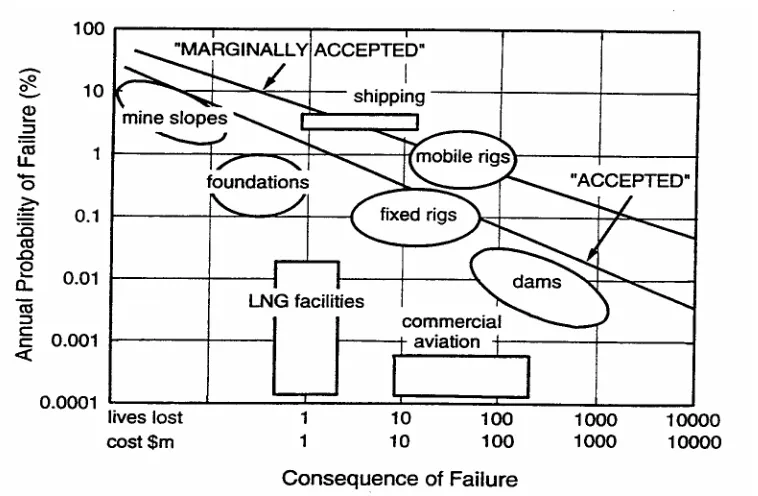
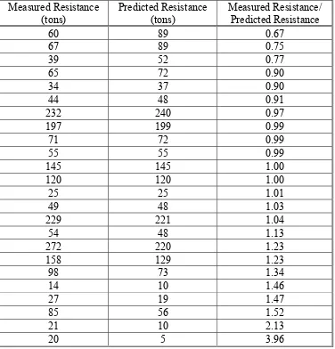
3-1 Values of Resistance Factors Corresponding by Fitting for Different Values of Safety Factor and Dead to Live Load Ratios for (D = 1.25 and (L = 1.75 3-2 Summary of Measured and Predicted Driven Pile Axial Soil Resistance Using
Meyerhof Procedure
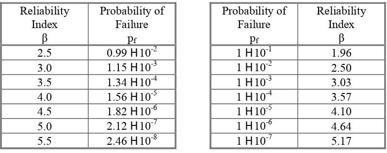
3-3 Relationship Between Probability of Failure and Reliability Index for Lognormal Distribution
3-4 Summary of Resistance Statistics 3-5 Statistics for Bridge Load Components
3-6 Resistance Factors for Axially Loaded Driven Piles in Sand, In-Situ Methods 3A-1 Relationship Between Probability of Failure and Reliability Index for Normal
Distribution
4-1 Relative Movements Needed to Achieve Active of Passive Earth Pressure Conditions
4-2 Equivalent Height of Soil for Vehicular Loading
4-3 Values of V0 and Z0 for Various Upstream Surface Conditions 4-4 Base Pressure, PB, for Va = 160 km/hr
4-5 Seismic Performance Zones 4-6 Site Coefficients
4-7 Classification of Soil Profile Types
4-8 Response Modification Factors for Substructure Design 4-9 Response Modification Factors for Connector Design 4-10 Load Combinations and Load Factors
4-11 Load Factors for Permanent Loads, (P 4-12 Minimum Soil Cover for Culverts 4-13 Multiple Presence Factors
4-14 Unfactored Vertical Loads and Resisting Moments 4-15 Unfactored Horizontal Loads and Overturning Moments 4-16 Load Factors
4-17 Factored Vertical Loads 4-18 Factored Horizontal Loads
LIST OF TABLES (continued)
4-20 Factored Moments from Horizontal Forces (Mh) 4-21 Unfactored Pier Loads and Moments
4-22 Load Combinations and Load Factors 4-23 Load Factors for Permanent Loads, (P 4-24 Moment Magnification Factors, (
4-25 Summary of Factored Loads and Moments in Pier Stem
4-26 Summary of Factored Axial Loads and Average Bearing Pressures at Base of Pier Stem
4-27 Critical Load Combinations for Deep Foundations
4-28 Critical Load Combinations for Spread Footing Foundations
4-29 Summary of Factored Loads for Critical Foundation Design Load Combinations 5-1 Guideline Minimum Boring and Sampling Criteria
5-2 Comparison of Ground Investigation Cost to Project Cost Overruns 5-3 Estimates of In-Situ Test Variability
5-4 Selected Major Sources of Error in the Standard Penetration Test 5-5 Major Sources of Error in the Cone Penetration Test
5-6 Major Sources of Error in the Vane Shear Test 5-7 Major Sources of Error for the Pressuremeter Test
5-8 Summary of Inherent Soil Variability and Measurement Variability for Index Tests 5-9 Index Test and Inherent Variability of Calcareous Mudstone
5-10 Summary of Inherent Soil Variability and Measurement Variability for Strength Tests
5-11 Selected Variability of Rock Modulus Values
5-12 Problem Conditions Requiring Special Consideration
5-13 Field and Laboratory Shear Strength Test Data for Example Problem
6-1 Correlation of In-Situ Test with Foundation Performance for Cohesive Soils 6-2 Correlation of In-Situ Test with Foundation Performance for Cohesionless Soils 6-3 Correlations of In-Situ Tests with Engineering Behavior for Cohesive Soils 6-4 Correlations of In-Situ Tests with Engineering Behavior for Cohesionless Soils 6-5 Soil Property Correlations with Index Test Data
LIST OF TABLES (continued) 7-1 Values of 8R and COVR
7-2 Values of 8QD and COVQD
7-3 Load Factors for Permanent Loads, (P 7-4 Values of QD/QL
7-5 Values of Target Reliability Index, $T
7-6 Values of N for Nordlund's Method Calculated Using Reliability Theory
7-7 Values of N for Nordlund's Method Calculated Using the Simplified Approximate Reliability Method
7-8 Values of N for Nordlund's Method Calculated Using Fitting with ASD 8-1 Factors of Safety on Ultimate Geotechnical Capacity of Spread Footings for
Bearing Capacity and Sliding Failure
8-2 Factors of Safety on Ultimate Bearing Capacity of Spread Footings on Soil 8-3 Variable Factors of Safety on Ultimate Bearing Capacity of Spread Footings 8-4 Suggested Minimum Factors of Safety for Overall Slope Stability from FHWA
8-5 Required Minimum Factors of Safety for Overall Slope Stability from AASHTO ASD
8-6 Limit States for Design of Spread Footing Foundations
8-7 Resistance Factors for Semi-Empirical Evaluation of Bearing Capacity for Spread Footings on Sand Using Reliability-Based Calibration
8-8 Resistance Factors for Geotechnical Strength Limit State for Shallow Foundations
8-9 Comparison of ASD Factor of Safety with LRFD Equivalent Factor of Safety for Spread Footing Foundations
8-10 Unfactored and Factored Vertical Loads 8-11 Unfactored and Factored Horizontal Loads
8-12 Unfactored and Factored Moments from Vertical Forces (Mv) 8-13 Unfactored and Factored Moments from Horizontal Forces (Mh) 8-14 Consolidation Settlement Calculation
8-15 Summary of Eccentricity Check
8-16 Summary of Factored Bearing Pressures 8-17 Summary of Sliding Resistance
8-18 Summary of Spread Footing Design by LRFD and ASD
9-1 Factor of Safety on Ultimate Axial Geotechnical Capacity Based on Level of Construction Control
9-2 Allowable Stresses in Piles
LIST OF TABLES (continued)
9-4 Resistance Factors for Driven Piles for Estimating the Axial Geotechnical Pile Capacity Using Reliability-Based Calibration
9-5 Resistance Factors for Geotechnical Strength Limit State for Axially Loaded Piles 9-6 Resistance Factors for Structural Design of Axially-Loaded Piles Calibrated to ASD 9-7 Comparison of ASD Factor of Safety with LRFD Equivalent Factor of Safety
Geotechnical Strength Limit State for Axially-Loaded Piles 9-8 Conditions When Downdrag Should be Considered in Design 9-9 Permissible Stresses During Pile Driving
9-10 Load Factors
9-11 Tabulation of Side Resistance Along Pile Length
9-12 Determination of Required Pile Group Size Based on ASD 9-13 Determination of Required Pile Group Size Based on LRFD
9-14 Summary of Factored Loads for Critical Foundation Design Load Combinations 9-15 Pile Spacing Effect
10-1 Factor of Safety on Ultimate Axial Geotechnical Capacity
10-2 Factors of Safety on Ultimate Geotechnical Capacity Based on Design Life and Level of Construction Control
10-3 Limit States for Design of Drilled Shaft Foundations
10-4 Resistance Factors for Drilled Shafts for Estimating the Ultimate Axial Shaft Capacity Using Reliability-Based Calibration
10-5 Resistance Factors for Geotechnical Strength Limit States for Axially Loaded Drilled Shafts
10-6 Resistance Factor for Structural Design of Axially-Loaded Drilled Shafts 10-7 Comparison of ASD Factor of Safety with LRFD Equivalent Factor of Safety,
Geotechnical Strength Limit State for Axially-Loaded Shafts
10-8 Comparison of ACI and AASHTO LRFD Load and Resistance Factors for Drilled Shafts
10-9 Conditions When Downdrag Should be Considered in Design 11-1 Limit States for Design of Gravity Retaining Walls and Abutments
11-2 Summary of Parametric Study Results from LRFD Eccentricity Calibration 12-1 Strength and Service Limit States for Design of Prefabricated Modular Walls 12-2 Unfactored Unit Properties of 2.44-m Long Wall Modules
12-3 Unfactored Vertical Loads and Resisting Moments 12-4 Unfactored Horizontal Loads and Overturning Moments 12-5 Load Factors
LIST OF TABLES (continued) 12-7 Factored Horizontal Loads
12-8 Factored Moments from Vertical Forces (Mv) 12-9 Factored Moments from Horizontal Forces (Mh) 12-10 Summary of Eccentricity Check
12-11 Summary of Maximum Bearing Pressures 12-12 Summary of Sliding Resistance
12-13 Summary of Spread Footing Design by LRFD and ASD 13-1 Factors of Safety for Anchored Walls
13-2 Maximum Allowable Tensile Loads for Ground Anchors
13-3 Strength and Service Limit States for Design of Anchored Walls 13-4 Resistance Factors for Anchored Walls
13-5 Comparison of FSASD and FSLRFD for Anchored Walls
13-6 Comparison of ASD Allowable Load/Stress with the LRFD Equivalent Load/Stress for Structural Design of Ground Anchors
13-7 Ultimate Unit Resistance of Anchors in Soil 13-8 Ultimate Unit Resistance of Anchors in Rock
14-1 Factors of Safety for External Stability of MSE Walls
14-2 ASD Criteria for Internal Stability Evaluation of Reinforcements for MSE Walls 14-3 Strength and Service Limit States for Design of MSE Walls
14-4 Resistance Factors for Strength Limit State of MSE Walls 14-5 Creep Reduction Factors for Polymeric Reinforcements
14-6 Relationship Between Joint Width and Limiting Distortion of MSE Wall Facing 14-7 Coefficient of Resistance for Steel Reinforcements
14-8 Equivalent Height of Soil for Vehicular Loading 14-9 Unfactored Vertical Loads/Moments
14-10 Unfactored Horizontal Loads/Moments 14-11 Load Factors and Load Combinations 14-12 Factored Vertical Loads
14-13 Factored Horizontal Loads
LIST OF TABLES (continued) 14-17 Summary for Bearing Check
14-18 Factored Vertical Load and Moment at Reinforcement Levels for Reinforcement Tensile Resistance Evaluation
14-19 Summary of Factored Horizontal Loads for Reinforcement Tensile Resistance Evaluation
14-20 Factored Vertical Load and Moment at Reinforcement Levels for Pullout Resistance Evaluation
14-21 Summary of Factored Horizontal Loads for Reinforcement Pullout Resistance Evaluation
14-22 Pullout Resistance in Reinforcement Levels 14-23 Equivalent Height of Soil for Vehicular Loading 14-24 Unfactored Vertical Loads/Moments
14-25 Unfactored Horizontal Loads/Moments 14-26 Load Factors and Load Combinations 14-27 Factored Vertical Loads
14-28 Factored Horizontal Loads
14-29 Factored Moments from Vertical Loads 14-30 Factored Moments from Horizontal Loads 14-31 Summary for Eccentricity Check
14-32 Factored Vertical Load and Moment at Reinforcement Levels 14-33 Summary of Factored Horizontal Loads
14-34 Summary of Maximum Factored Horizontal Forces for Connection of Strip to Facing
14-35 Pullout Resistance in Reinforcement Levels
15-1 Factor of Safety on Ultimate Structural Capacity of Flexible Culverts 15-2 Limit States Applicable for Design of Metal Pipes and Arches 15-3 Limit States Applicable for Design of Thermoplastic Pipe 15-4 Load Factors for Flexible Culvert Design
15-5 Resistance Factors for Design of Flexible Culverts
15-6 Comparisonof Effective Factors of Safety for Flexible Culverts - Strength I Limit State
15-7 Strength and Elastic Properties of Aluminum and Steel Culverts 15-8 StrengthandElastic Properties of PE and PVC Culverts
15-9 Flexibility Factor Limits for Corrugated Metal, Structural Plate and Thermoplastic Pipe
LIST OF TABLES (continued)
16-1 Load Coefficients/Factors for LFD of Rigid Culverts 16-2 Load Factors for LRFD Rigid Culverts
16-3 Limit States Applicable for Design of Reinforced Concrete Pipes
16-4 Resistance/Strength - Reduction Factors for Precast Reinforced Concrete Culverts A-1 Prefixes Used with Metric Units
LIST OF FIGURES
Figure
No. Title
2-1 Factor of Safety for ASD 2-2 LRFD Design Approach 2-3 Variation of Load and Resistance 2-4 Variation of Load and Resistance 2-5 Reliability Index, $
2-6 Empirical Rates of Failure for Civil Works Facilities 2-7 Example Condition for Service Limit State Evaluation 2-8 Example Condition for Strength Limit State Evaluation
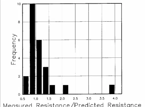
3-1 Histogram of Measured to Predicted Axial Driven Pile Resistance for Example Problem 3.2
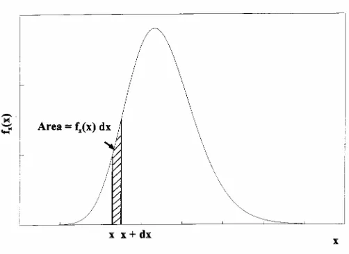
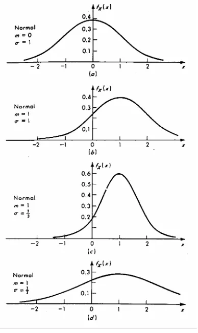
3-2 Lognormal Probability Density Function 3-3 Standard Normal Density Function
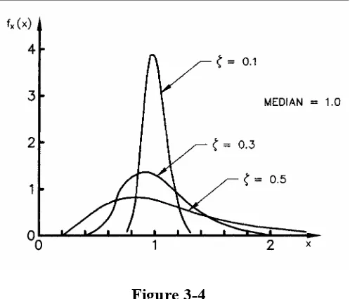
3-4 Lognormal Density Function
3-5 Probability Density Functions for Normally Distributed Load and Resistance 3-6 Definition of Reliability Index, $ for Lognormal Distributions of
R and Q
3-7 Reliability Index for Meyerhof’s SPT Method
3-8 Resistance Factors for Meyerhof’s SPT Method for $T = 2.0 and 2.5 4-1 Typical Loading for Substructure Design
4-2 Downdrag Loading
4-3 Location of Resultant Lateral Earth Pressure
4-4 Earth Pressure Distribution for Anchored Wall Design
4-5 Earth Pressure Distribution for MSE Wall Design with Level Backfill Surface 4-6 Earth Pressure Distribution for MSE Wall Design with Sloping Backfill Surface 4-7 HS20 Truck Configuration
4-8 Horizontal Pressure on Wall Due to Uniformly-Loaded Strip Pressure 4-9 Earthquake Loads on a Bridge
4-10 Definition Sketch for Monobe-Okobe Analysis
4-11 Load Combination for Evaluation of Sliding Resistance of a Cantilever Retaining Wall Supported on a Spread Footing
4-12 Load Combination for Evaluation of Bearing Resistance and Eccentricity of a Cantilever Retaining Wall Supported on a Spread Footing
LIST OF FIGURES (continued)
Figure No. Title
4-14 Soil Blocks Mobilized by Arching Over Culverts
4-15 Design Truck Pressure Distribution From Elastic Theory
4-16 Comparison of AASHTO Live Load Pressures Through Earth Fills 4-17 Surface Loading Pattern for Design Truck and Design Tandem 4-18 Distributed Area at Depth for Design Truck and Design Tandem 4-19 Live-Load Distribution Through Soil for Design Truck
4-20 Live-Load Distribution Through Soil for Design Tandem 4-21 Schematic of Example Problem
4-22 Retaining Wall Area Designations for Weight of Concrete
5-1 Reliability Variation with Sample Size for Indirect Testing for Mobilized Undrained Shear Strength
5-2 Optimization of Foundation and Exploration Cost
5-3 Illustrative Variation of Resistance Factor with Resistance Coefficient of Variability
5-4 Split-Barrel Sampler
5-5 Electrical Friction-Cone Penetrometer Tip 5-6 Field Vane Geometries and Sizes
5-7 Menard Pressuremeter Equipment 5-8 Thin-Walled Tube Sampler 5-9 Double-Tube Core Barrel
5-10 Histograms of Intact Rock Strength Properties 6-1 Uncertainty in Soil Property Estimates
6-2 Comparison of Field and Laboratory Shearing Modes
6-3 Correlation of CPT Tip Resistance, SPT N-Value and Mean Particle Size 6-4 Correlation of CPT Tip Resistance, SPT N-Value and Fines Content
6-5 Correlation of Triaxial Compression Effective Stress Friction Angle with Cone Penetration Tip Resistance
6-6 Field Vane Shear Correction Factor
6-7 Pressuremeter Modulus versus N Value for Cohesionless Soil 6-8 Pressuremeter Modulus versus N Value for Cohesive Soils
6-9 Correlation of CPT Tip Resistance with Constrained Modulus and Relative Density for NC Sands
LIST OF FIGURES (continued)
Figure No. Title
6-11 Correlation Between Normalized Undrained Shear Strength and Liquidity Index for NC Clays
6-12 Compression and Unload-Reload Indices versus Plasticity Index
6-13 Normalized Undrained Shear Strength Versus Undrained Strength Ratio from CIUC and UU Tests
6-14 Example Problem, Site Exploration Plan for Western Approach
8-1 Circular Arc Slope Stability Failure Surface Showing Typical Soil Slice Forces 8-2 Generalized Flow Chart for Spread Footing Design by ASD and LRFD
8-3 Comparison of Resultant Force Location for Footing on Soil Using ASD and LRFD
8-4 Comparison of Resultant Force Location for Footings on Rock Using ASD and LRFD
8-5 Schematic of Example Problem 8-6 Reduced Footing Dimensions
8-7 Procedure for Estimating Sliding Resistance of Footings on Clay 9-1 Generalized Flow Chart for Driven Pile Design by LRFD and ASD 9-2 Pile Group Loading
9-3 Generalized Problem Geometry and SPT Design Envelope
9-4 Representative Pile and CPT Tip Resistance Profile Used in Example 9-5 Representative Pile and CPT Side Resistance Profile Used in Example 9-6 Pile Cap and Pile Layout
9-7 Axial Load, Pu, Summary
9-8 Strong Axis Maximum Bending Moment, Mux, Summary 9-9 Weak Axis Maximum Bending Moment, Muy, Summary 9-10 Pile Settlements
10-1 Generalized Flow Chart for Drilled Shaft Design by LRFD and ASD 10-2 Soil Profile for Example
10-3 Shaft Group Layout for Example
10-4 Preliminary Longitudinal Shaft Reinforcement for Example
11-1 Generalized Flow Chart for Conventional Retaining Wall and Abutment Design by ASD and LRFD
12-1 Generalized Flow Chart for Modular Retaining Wall Design 12-2 Schematic of Example Problem
LIST OF FIGURES (continued)
Figure No. Title
12-4 Bearing Pads at Rear and Front of Modules 13-1 Anchored Wall Nomenclature
13-2 Generalized Flow Chart for Anchored Wall Design by ASD and LRFD 13-3 Settlement Profiles Behind Anchored Walls
13-4 Schematic of Example Problem
13-5 Lateral Earth Pressure Diagram for Soldier Pile Embedment into Cohesionless Soil
14-1 Generalized Flow Chart for MSE Wall Design by ASD and LRFD 14-2 Pullout Factors for Inextensible Mesh and Grid Reinforcement
14-3 Determination of Failure Plane and Earth Pressure Coefficients for MSE Wall with Inextensible Reinforcements
14-4 Problem Geometry
14-5 Pressure Diagram for Computation of quniform for Reinforcement Tensile Resistance Evaluation of Layer 1
14-6 Pressure Diagram for Computation of quniform for Reinforcement Pullout Resistance Evaluation of Layer 1
14-7 Problem Geometry
14-8 Earth Pressure Distribution for MSE Wall with Broken Back Backfill Surface 14-9 Geometry of Assumed Failure Surface for Example Problem
14-10 Pressure Diagram for Computation of quniform for Internal Stability Evaluation of Layer 1
15-1 Generalized Flow Chart for Flexible Culvert Design by ASD and LRFD 15-2 Comparison of Flexible Culvert Deflection Modes in Loose and Dense Soils 15-3 Problem Definition
15-4 Pressure Distribution at Pipe Crown for Design Truck 15-5 Pressure Distribution at Pipe Crown for Design Tandem 16-1 D-Load Test Setup
16-2 Comparison of AASHTO Live Load Pressures Through Earth Fills 16-3 Paris (a) and Olander (b) Pressure Distributions
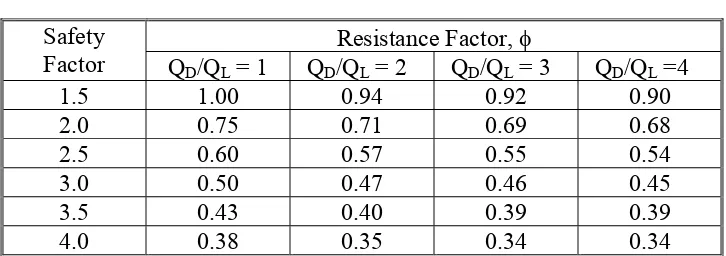
LIST OF SYMBOLS
A = Acceleration coefficient for earthquake load evaluation (dim)
A = Cross-sectional area of soil reinforcement less any sacrificial thickness (m2) A = Cross-sectional area of structural element (m2)
A = Cross sectional area of pipe wall (m2)(15.2.1) A = Wall area per unit length (m2/m)(15.3.2) a = Net area ratio for cone penetrometer (dim) AN = Effective footing area (m2)
aB = Barge bow damage length (m)
Ab = Surface area of transverse reinforcement in bearing, less sacrificial thickness of cross bars (m2)
AD = Distributed area at depth DE (m2)
AF = Annual frequency of collapse of a bridge component (dim) Ag = Gross area of concrete section (m2)
Ap = Area of pile or shaft tip (m2)
As = Net cross-sectional area reduced for corrosion (m2)(14.2.2)
As = Total top and bottom surface area of reinforcement along, Leff'' less any sacrificial thickness (m2)
Ast = Area of reinforcing steel (m2) AL = Group axle load (kN)
As = Area of pile or shaft side surfaces (m2) B = Width of footing (m)
B = Base width (m)
B = Effective backslope (deg) B = 1 - 0.33 hw/h (dim)
BN = Effective width of footing (m) BBP = Bearing pad width (m)
Bc = Outside diameter or width of pipe (m) Brc = Out-to-out vertical rise of pipe (m) BFE, BFLL = Bedding factor (dim) BR = Vehicular braking force (kN) c = Cohesion of soil (kPa)
Ca = Coefficient for effect of pier width to ice thickness ratio where flow fails by crushing (dim)
CC = Compression Index (dim) Ccr = Recompression Index (dim) CE = Vehicular centrifugal force (kN) CH = Hydrodynamic mass coefficient (dim)
Co = Unconfined compressive strength of rock core (kPa) COV = Coefficient of variation (dim)
COVINHERENT = Coefficient of variation of inherent soil variability (dim) COVMEASUREMENT = Coefficient of variation of property measurement (dim) COVMODEL = Coefficient of variation of predictive model (dim)
LIST OF SYMBOLS (continued) COVQL = Coefficient of variation of live load (dim) COVR = Coefficient of variation of resistance (dim)
COVRA = Coefficient of variation for soil internal friction angle using Nordlund Method (dim)
COVRN = Coefficient of variation for pile capacity using Nordlund Method (dim) COV8 = Coefficient of variation of overall bias (dim)
COV8i = Coefficient of variation of a bias factor (dim)
Cn = Horizontal inclination of pier nose to a vertical line (dim) CR = Force effects due to creep (kN)
CRF = Creep reduction factor from creep tests or Table 14-5 (dim)
Csm = Elastic seismic response coefficient for mth mode of vibration (dim) CT = Vehicular collision force (kN)
Cur = Recompression Index (dim) CV = Vessel collision force (kN)
Cv = Coefficient of consolidation (m2/sec) D = Pile, shaft or culvert diameter (m) D = Diameter of vane (mm)
D = D-load (three-edge bearing resistance of reinforced concrete pipe, corresponding to an experimentally observed 0.25 mm width crack or to ultimate load capacity of culvert (kN/m)
DC = Dead load of structural components and non-structural attachments (kN) DD = Downdrag load (kN)
DE = Depth below road surface (m) DLP = Distributed lane pressure (kPa)
DTP = Distributed truck/tandem pressure (kPa) Dr = Relative density (percent)
DW = Dead load of wearing surfaces and utilities (kN) DWT = Dead weight tonnage of vessel (metric ton)
D10 = Particle diameter for which material is 10% finer by weight (mm) D50 = Mean particle diameter (mm)
E = Young's modulus (kPa) e = Eccentricity (m)
eB, eL = Eccentricity of load resultant with respect to centroid of footing (m) Ec = Thickness of metal reinforcement at end of service life (mm) ecc = Reduction factor for accidental load eccentricity (dim)
ED = Dilatometer modulus averaged over a depth interval of 5m (kPa) EH = Horizontal earth pressure load (kN)
Em = Modulus of elasticity of culvert material (kPa) emax = Maximum allowed eccentricity (m)
En = Nominal thickness of steel reinforcement at construction (mm) EPMT = Pressuremeter modulus (kPa)
ES = Earth surcharge load (kN)
Es = Sacrificial metal thickness expected to be lost by uniform corrosion during service life of structure (mm)
EQ = Earthquake load (kN)
LIST OF SYMBOLS (continued)
EV = Vertical pressure from dead load of earth fill (kN) F = Horizontal force caused by ice flows (kN)
Fb = Horizontal force caused by ice flows which fail by bending (kN)
FC = Construction damage factor for geosynthetic reinforcement ranging from 1.1 to 3.0, and taken as 3.0 without tests (dim)
Fc = Horizontal force caused by ice flows which fail by crushing (kN) fNc = Concrete compressive strength (kPa)
fcr = Buckling strength of culvert wall (kPa)
FD = Durability factor for geosynthetic reinforcement ranging from 1.1 to 2.0, and taken as 2.0 without tests (dim)
fd = Coefficient of resistance to direct sliding of reinforcement (dim) Fe = Soil-structure interaction factor (dim) (4.5)
FF = Flexibility Factor (m/kN)
FFmax = Suggested Maximum Permissible Flexibility Factor (m/kN) fL = Material limit stress (kPa)
fpe = Concrete compressive stress due to prestressing (kPa)
FR = Frictional force effects due to sliding between structure members (kN) FS = Factor of safety (dim)
fs = Cone penetrometer side resistance (kPa) FSASD = ASD Factor of Safety (dim)
FSLRFD = LRFD equivalent factor of safety (dim) fu = Specified minimum tensile strength (kPa) fx(x) = Probability density function
Fy = Minimum yield stress (kPa) fy = Yield strength of metal (kPa)
f* = Apparent coefficient of friction at each reinforcement level (dim) g = Gravitational acceleration (9.8/m/s2)
func {overline g} = Mean value of g(R,Q) g(R,Q) = Combined probability density function
H = Design height of wall and height of backfill above culvert crown (m) (4.5) h = Nominal height of horizontal earth pressure diagram (m)
h = Height of ground surface above culvert (m) h = Depth of reinforced soil (m)
HDF = Reduction factor for hidden defects due to damage during pile driving (dim) heq = Equivalent height of soil for design live load (m)
LIST OF SYMBOLS (continued) k = Horizontal earth pressure coefficient (dim) k = Coefficient of permeability (m/s)
k = Soil correlation factor (dim)
ka = Active earth pressure coefficient (dim)
Kae = Seismic active earth pressure coefficient (dim) KE = Vessel collision energy (joule)
kh = Lateral earth pressure coefficient (dim)
kh = Horizontal acceleration coefficient (dim) (4.2.1.3) ko = At-rest earth pressure coefficient (dim)
Kpe = Seismic passive earth pressure coefficient (dim) ks = Coefficient of earth pressure due to surcharge (dim) kv = Vertical acceleration coefficient (dim)
L = Footing length, anchor bond length and span length of culvert (m) L = Horizontal spacing between vertical wall elements (m)(13.3.6.1) L = Soil reinforcement length (m)
l = Length of tire contact in direction of travel (m) l = Le = Length of geogrid beyond failure plane (m) LN = Effective footing length (m)
R = Incremental length of sliding surface in slope stability analysis (m) LD = Distributed length of wheel load (m)
M = Vessel displacement tonnage (metric ton) M = Constrained modulus (kPa)
m = Multiple presence factor (dim)
Mdt = Tangent constrained drained modulus (kPa)
Mmax = Factored maximum flexural moment in facing or vertical wall element (kN-m/m) Ms = Confined modulus of soil (kPa)
N = Number of data values (dim) N = SPT blow count (blows per 30 cm) N = Normal force (kN)
n = Sample size
n = Number of transverse bearing members behind failure plane (dim) Nk = Cone bearing factor (dim)
Np = Passive resistance factor based on site-specific pullout tests, or as defined by Figure 14-2 (dim)
OCR = Overconsolidation ratio (dim) P = Wheel load (kN)
p = Effective ice crushing strength (kPa) (4.2.2.12) p = Live load intensity (kPa)
p = Average factored lateral pressure acting on vertical wall element or facing (kPa) PA = Probability of vessel aberrancy (dim)
LIST OF SYMBOLS (continued) pa = Lateral earth pressure (kPa)
pa = Atmospheric pressure (kPa)
Pae = Seismic active earth pressure (kN/m)
Pall = Allowable axial, tensile or flexural structural capacity (kN) Pall(LRFD) = LRFD equivalent allowable tensile load (kN) PB = Base wind pressure (kPa) (4.2.2.8)
PB = Equivalent static vessel impact force (kN)
PC = Probability of bridge collapse due to a collision with an aberrant vessel (dim) PD = Design wind pressure (kPa)
pf = Probability of failure (dim)
Pfg = Nominal pullout resistance of steel grid reinforcement (kN)
Pfs = Nominal pullout capacity of ribbed or smooth steel reinforcing strips (kN) PH = Horizontal load (kN)
Ph = Horizontal component of lateral earth pressure per unit length of wall (kN/m) ph = Horizontal stress (kPa)
PI = Plasticity Index (dim) PL = Pedestrian live load (kN) PL = Factored crown pressure (kPa)
PN = Wind pressure normal to structure component (kPa) Pn=Pult = Ultimate (nominal) structural resistance (kN)
Pn = Ultimate anchor tensile resistance or GUTS (kN)(13.2.2)
Pr = Factored structural resistance of reinforcements, facing and connections (kN) PP = Wind pressure parallel to structure (kPa)
Ppe = Seismic passive earth pressure (kN/m) Pr = Factored structural resistance (kN) ps = Probability of survival (dim)
Pv = Vertical component of lateral earth pressure resultant per unit wall length (kN/m) Q = Load or design load (kN)
q = Surcharge pressure (kPa)
q = Average pressure of an assumed rectangular distribution (kPa) func {overline Q} = Mean load (kN)
func {overline q} = Magnitude of uniform distribution of soil pressure (kPa)
Qa = Ultimate unit resistance between grout/soil/rock in anchor bond zone per unit length (kN/m)
Qall = Allowable design load (kN)
qc = Cone penetrometer tip resistance (kPa) QD = Dead load (kN)
Qep = Nominal passive resistance of foundation material (kN) Qi = Force effect, stress or stress resultant (kN or kPa) QL = Live load (kN)
qmax = Maximum unit bearing stress (kPa) qmin = Minimum unit bearing stress (kPa)
Qn = Nominal sliding resistance of footing (kN) Qp = Ultimate pile tip resistance (kN)
qp = Unit tip resistance (kPa)
LIST OF SYMBOLS (continued) qR = Factored unit bearing resistance (kPa) Qs = Ultimate pile side resistance (kN)
qs = Uniform surcharge applied to upper surface of active earth wedge (kPa) qs = Vehicular live load surcharge (kPa)
qs = Unit shear resistance (kPa)
qT = Corrected cone tip resistance (kPa) Qult = Ultimate geotechnical resistance (kN) qult = Ultimate unit bearing resistance (kPa)
quniform = Rectangular distribution of soil pressure (kPa)
QJ = Nominal shear resistance between footing and foundation material (kN) R = Resistance (kN)
R = Radius of curvature of traffic lane (m) (4.2.2.3)
R = Earthquake response modification factor (dim) (4.2.2.11) R = ADTT reduction factor (dim) (4.5)
R = Schmidt Hammer Rebound (dim)
R = Radius of culvert cross section at neutral axis (m) r = Radius of gyration of culvert wall (m/m)
r2 = Coefficient of determination (dim) func {overline R} = Mean resistance (kN) Rm = Measured resistance (kN) Rn = Nominal (ultimate) resistance (kN) Rr = Factored resistance (kN or kPa)
S = Site coefficient for earthquake load evaluation (dim) (4.2.2.11) S = Diameter or span of culvert (m) (4.5)
S = Soil spreading factor (dim) (4.5)
Sc = Estimated total consolidation settlement (mm) S.D. = Standard deviation
SE = Force effects due to settlement (kN) SH = Force effects due to shrinkage (kN) Si = Internal diameter of culvert (m) SS = Seam strength (kN/m)
Su = Undrained shear strength (kPa)
T = Limit State tensile capacity from creep tests (kN) T = Tangential force (kN)
t = Ice thickness (m)
TL = Factored thrust in culvert wall (kN/m)
Tn = Ultimate wide width tensile yield strength (kN) To = Tensile Strength (kPa)
Tw = Serviceability State tensile capacity at which total strain is not expected to exceed 5% based on wide-width tensile test design life of structure (kN)
TR = Highest load level at which log time-creep-strain rate continues to decrease with time within required lifetime without either brittle or ductile failure (kN)
T5 = Tension level at 5% strain based on wide width tensile test (kN) ti = Initial thickness of reinforcing (m)
LIST OF SYMBOLS (continued)
TG = Force effects due to temperature gradient deformation (kN) TU = Force effects due to uniform temperature deformation (kN) ubt = Pore Pressure measured behind cone tip (kPa)
v = Highway design speed (m/s) V = Vessel impact velocity (m/s) VAF = Vertical Arching Factor (dim) (4.5) VB = Base wind velocity of 160 km/hr
VDZ = Design wind velocity at design elevation (km/hr) Vest = Most likely value of property
Vmax = Largest conceivable value of property Vmin = Lowest conceivable value of property VP = Compression Wave Velocity (m/s)
V10 = Wind velocity at 10 m above low ground or design water level (km/hr) V0 = Friction velocity (km/hr)
w = Width perpendicular to direction of travel of surface tire contact area (m) w = Width of grid reinforcement mat (m)
wi = Initial width of reinforcing (m) wL = Liquid limit (%)
wn = Natural water content (%) wP = Plastic limit (%)
w100 = Width of reinforcing after 100 years (m) WA = Water load and stream pressure (kN)
WD = Width perpendicular to direction of travel for distributed area (m) WE = Total unfactored earth load per unit length (kN/m)
WL = Total unfactored live load per unit length (kN/m) WT = Weight of soil slice in slope stability analysis (kN) WT = WE + WL (kN/m)
WL = Horizontal wind pressure effects on vehicles (kN) WS = Wind load on structure (kN)
x = Height of section for vertical element being considered (m) func {overline x} = Mean value of data
xi = Data set value
Xo = Location of resultant from toe of wall (m)
Z = Structure height above low ground or design water level (m) Z = Depth below effective top of wall to reinforcement (m) z = Depth from ground surface (m) (4.2.1.3)
Zo = Friction length of upstream fetch (m)
" = Inclination of pier nose to vertical (deg)
" = Constant (dim)
" = Adhesion (dim)
$ = Reliability index, func {overline g~/._g} (dim)
$ = Slope of wall backface (deg)
$ = Coefficient for determining downdrag force by $ method (dim)
$ = Load combination coefficient (dim)
LIST OF SYMBOLS
(EH = Load factor applied to horizontal earth pressure (dim)
(EV = Load factor applied to vertical earth pressure (dim)
(LS = Load factor applied to live surcharge load (dim)
(s = Soil density (kN/m3)
) = Lateral movement needed to develop active or passive earth pressure (m)
* = Angle of friction between soil and wall (deg)
*i = Estimated displacement or differential displacement (mm)
*max = Maximum tolerable settlement (mm)
*n = Tolerable or differential displacement or movement (mm)
) p = Constant horizontal earth pressure due to uniform surcharge (kPa)
) P = Constant horizontal earth pressure due to uniform surcharge (kPa)
) ph = Horizontal earth pressure due to surcharge (kPa)
*tol = Tolerable displacement or differential displacement (mm)
. = Standard deviation of a lognormally distributed data set
2 = Angle between wind direction and normal to structure component (deg.) (4.2.2.8)
2 = Skew angle (deg) (4.4)
0 = Load modifier to account for effects of ductility, redundancy and operational importance (dim)
0 = Efficiency factor for piles (dim)
0D = Load modifier account for effects of ductility (dim)
0I = Load modifier account for effects of operational importance (dim)
0R = Load modifier account for effects of redundancy (dim)
8 = Bias factor (dim)
8RA = Bias factor for soil internal friction angle using Nordlund Method (dim)
8RN = Bias factor for pile capacity using Nordlund Method (dim) µ = Correction factor (dim)
< = Poisson’s Ratio (dim)
>m = Lognormal mean
LIST OF SYMBOLS (continued) Dtol = Tolerable elastic settlement (mm)
F = Standard deviation of data set
Fall = Allowable stress (kPa)
Fall = Allowable axial, tensile or flexural stress (kPa)
Fall(LRFD) = LRFD equivalent allowable anchor tensile stress (kPa)
Fg = Standard deviation of g(R,Q), combined probability density function
FH = Horizontal stress at reinforcing layer 1 = (pFvk(kPa)
Fn = Ultimate (yield) strength of steel (kPa)
Fn = Ultimate tensile capacity (kPa)
Fp = Preconsolidation stress (kPa)
Fult = Limit stress in culvert material (kPa)
FV = Pressure due to resultant vertical forces at reinforcement level (kPa)
Frv = Vertical effective stress (kPa)
Fvo = Total overburden stress (kPa)
Frvo = Effective vertical overburden stress (kPa)
Jav = Average cyclic stress (kPa)
N = Resistance factor (dim)
N = Internal friction angle (4.2.2.11)
N = Reduction factor to account for manufacturing variability (dim) (9.2.1)
Nr = Effective stress friction angle (deg)
Nep = Resistance factor for passive earth pressure component of sliding resistance (dim)
Nf = Internal angle of friction of reinforced soil zone (deg)
NNf = Effective stress friction angle (deg)
Nm = Modified resistance factor (dim)
Nqp = Resistance factor for tip resistance (dim)
Nqs = Resistance factor for side resistance (dim)
NR = Resistance factor for overall stability (dim)
Nrtc = Triaxial compression effective stress friction angle (deg)
NJ = Resistance factor for shear between footing and foundation material (dim)
CHAPTER 1 INTRODUCTION
1.1 Manual Objectives
In the US, the design of foundations, walls and culverts has traditionally been performed using allowable stress design (ASD) in which all uncertainty in loads and material resistance is combined in a factor of safety. For most highway engineering applications, a source document for ASD of substructures has been Division I of the AASHTO "Standard Specifications for Highway Bridges" (1996). In 1989, work began on an entirely new specification in which the uncertainty in load(s) is represented by a load factor(s) which generally has a value greater than one, and the uncertainty in material resistance(s) is represented by a resistance factor(s) which generally has a value less than one. This effort involved a team of about 50 consultants and contractors under the direction of Modjeski and Masters, Inc., and review by a project panel, AASHTO technical subcommittees, state highway departments, transportation authorities, and industry representatives. The AASHTO Load and Resistance Factor Design (LRFD) Specification was approved for use in 1994.
Due to the differences between the substructure design process by ASD and LRFD, FHWA sponsored development of this training course to present the fundamentals of LRFD to bridge design engineers, geotechnical engineers, engineering geologists and others who are responsible for design of bridge substructures using the AASHTO LRFD Specification. This manual focuses on the geotechnical aspects of substructure design.
The objectives of this manual are to provide the basis for an understanding of the:
y Differences between ASD and LRFD for substructure design y Benefits of LRFD for substructure design
y Importance of site characterization and selection of geotechnical design parameters
y Process for design of substructure elements by LRFD using the AASHTO LRFD Specifications as a guide
y Process for selection and application of load factors and load combinations y Methods available for calibration of resistance factors
y Basis for calibration of the AASHTO LRFD resistance factors for substructure design
y Procedures available for modifying or developing resistance factors to achieve designs comparable to ASD
design loads and ultimate resistance remain essentially unchanged. Therefore, verification of the quality of design and construction is equally important for ASD and LRFD.
1.2 Manual Outline
This manual consists of 17 chapters which describe the background, development and use of LRFD for highway bridge substructure design, and which present worked example problems for the majority of substructure types. The manual is intended as a reference document to supplement the Participant=s Workbook prepared for a National Highway Institute (NHI) two-day short course on
the design of substructures using LRFD. It is hoped that this reference manual and associated short course will facilitate the implementation of LRFD for highway bridge substructures and provide both the basis and impetus for further development and refinement of the AASHTO and state transportation department specifications for design by LRFD.
In addition to this Introduction and a Summary at the end of the manual, the content of the chapters includes the following topics:
y Chapter 2 - Transition to LRFD for Substructure Design y Chapter 3 - Principles of Limit State Design
y Chapter 4 - Loads
y Chapter 5 - Geotechnical Site Characterization y Chapter 6 - Geotechnical Design Parameter Selection y Chapter 7 - Calibration as Part of the Design Process y Chapter 8 - Spread Footing Design
y Chapter 9 - Driven Pile Design y Chapter 10 - Drilled Shaft Design
y Chapter 11 - Conventional Retaining Wall and Abutment Design y Chapter 12 - Prefabricated Modular Wall Design
y Chapter 13 - Anchored Wall Design
y Chapter 14 - Mechanically-Stabilized Earth Wall Design y Chapter 15 - Flexible Culvert Design
y Chapter 16 - Rigid Culvert Design
substructure design by ASD and LRFD, and identifies the performance limits important for substructure design (e.g., settlement, bearing capacity, sliding and overturning for spread footing foundations). Application of LRFD principles is illustrated in each chapter by example problems. In addition, several short student exercises are included to test your understanding of the information presented in the manual.
1.3 General References
Copies of the following references are available for use during the class:
AASHTO, 1994, LRFD Bridge Design Specifications, American Association for Transportation and Highway Officials, Washington, DC, 1st Ed.
AASHTO, 1997a, 1997 Interims to LRFD Highway Bridge Design Specifications, SI Units, American Association of State Highway and Transportation Officials, Washington, D.C., First Edition (1997 LRFD Interims)
AASHTO, 1996, Standard Specifications for Highway Bridges, American Association of State Highway and Transportation Officials, Washington, D.C., 16th Edition (1996 ASD)
AASHTO, 1997b, 1997 Interims to Standard Specifications for Highway Bridges, American Association of State Highway and Transportation Officials, Washington, D.C., 16th Edition (1997 ASD Interims)
Barker, R.M., J.M. Duncan, K.B. Rojiani, P.S.K. Ooi, C.K. Tan and S.G. Kim, 1991, Manuals for the Design of Bridge Foundations, National Cooperative Highway Research Program Report 343, Transportation Research Board, Washington, D.C., 308p.
CHAPTER 2
TRANSITION TO LRFD FOR SUBSTRUCTURE DESIGN 2.1 Introduction
Highway substructures (i.e., foundations and abutments) have traditionally been designed using Allowable Stress Design (ASD) methods whereas superstructure components have been designed used Load Factor Design (LFD) methods. This application of ASD for substructure design and LFD for superstructure design leads to uncertain and incompatible safety margins in the design of structure components. Solution of this problem requires a coherent method of design for the structure system. As described in subsequent chapters, Load and Resistance Factor Design (LRFD) represents an approach in which applicable failure and serviceability conditions can be evaluated considering the uncertainties associated with loads and material resistances. This chapter:
y Describes briefly the general process of allowable stress design y Introduces the general process of load and resistance factor design y Identifies the limit states that must be evaluated for structure design
y Briefly describes procedures used to calibrate LRFD and the AASHTO LRFD Specification (AASHTO, 1997a)
2.2 Allowable Stress Design
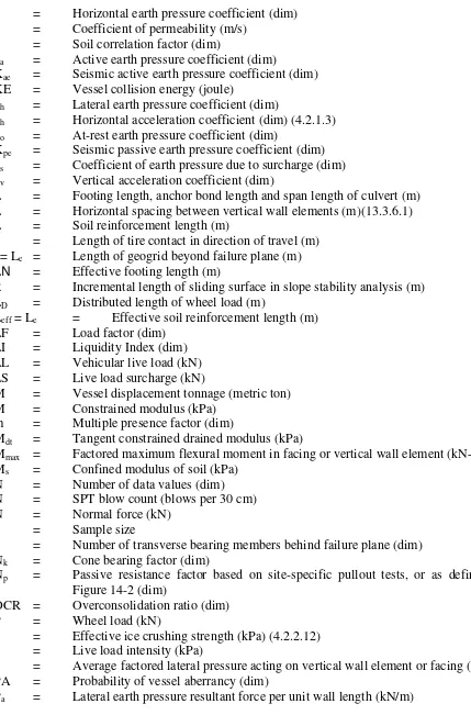
Existing practice for the geotechnical design of substructures follows the ASD approach, wherein all uncertainty in the variation of applied loads transferred to the foundation and the ultimate geotechnical capacity of the soil and rock to support the loads are incorporated in a factor of safety, FS. The factor of safety is an empirical, but arbitrary, measure used to reduce the potential for adverse performance (e.g., sliding failure of a footing and bearing failure of driven pile). The general relationship used in applying ASD takes the general form:
∑
≥ Q FSRn
(Eq. 2-1)
where:
Rn = Nominal (ultimate) resistance FS = Factor of safety
In practice, FS can range from values of about 1.2 to 6 depending on factors such as the type of problem being evaluated, the model used to estimate resistance and the experience of the designer. Graphically, the ASD process can be illustrated as shown in Figure 2-1.
Figure 2-1 Factor of Safety
Figure 2-1 illustrates one of the principal limitations of ASD, wherein the values of Q and Rn are assumed to be unique such that they have a probability of occurrence of unity. In addition, selection of FS is subjective, depends on the design models used and material parameters chosen, and is not inherently related to the probability of component failure. For geotechnical engineering, a rational design approach should consider the uncertainties associated with:
y Variability of engineering properties with aerial and vertical extent, and with time
y Reliability and applicability of property measurements
y Sufficiency and applicability of sampling and testing methods y Errors in prediction models used
y Errors in measuring material resistance y Variability in load prediction estimates
Although many or all of these sources of variability are usually considered by the designer using ASD, their consideration is generally qualitative rather than quantitative, leading to a wide range of failure probabilities among designs.
2.3 Load and Resistance Factor Design
n i
iQ R
∑
γ ≤φ (Eq. 2-2)where:
i
γ = Statistically-based load factor generally greater than one
i
Q = Load
n
R = Nominal (ultimate) resistance
φ = Statistically-based resistance factor generally less than one
Application of Eq. 2-2 is illustrated in Figure 2-2.
Figure 2-2
LRFD Design Approach
When applying LRFD, the estimated magnitudes of the various types of load effects are multiplied by appropriate load factors to determine the factored load effects, and the estimated nominal (ultimate) resistance is multiplied by a resistance factor prescribed for the model used to estimate material resistance and the field and/or laboratory test methods used to develop the material properties. For simplicity, the nominal and factored loads and the nominal and factored resistances are shown in Figure 2-2 as unique values. Of course, the load and material resistances vary, such as shown in Figure 2-3.
Figure 2-3
Variation of Load and Resistance
Figure 2-3 shows a possible variation of load and resistance as a function of the frequency or probability of occurrence. If the peak values of load, Q, and resistance, R, are defined by their respective mean values, Q and R , the equivalent ASD factor of safety is the ratio of R to Q as shown in the figure, and the margin of safety is the difference between R and Q . However, the figure also points out that some potential for failure exists in the area where the distributions of Q and R overlap. Therefore, unless very high factors of safety are used, some probability of failure will always exist.
Another factor which must be considered is the distribution of load and resistance. Figure 2-3 represents only one pair of distributions. Figure 2-4 shows that using the ratio of R to Q to define safety can be misleading. Two pair of load and resistance distributions are presented which have identical values of Q and R . The upper distribution for resistance is relatively small with steep flanks about R , whereas the lower distribution for resistance is broad with flat flanks, also about R . As a result, the area of overlap between the upper distributions of R and Q is small, representative of a small probability of failure. Conversely, the area of overlap between the lower distributions is large, representative of a greater probability of failure.
Figure 2-4
Distribution of Load and Resistance
Reliability-based design (or LRFD) is the process by which the risks and uncertainties associated with the safety of a system are defined in mathematical terms. In applying the process, the uncertainties (or distributions) of load and resistance are assumed to be independent, random variables, and the design risk is defined by the probability of failure, pf. To evaluate pf, a single probability density function is developed, as shown in Figure 2-5, which represent the combined distributions and uncertainties of Q and R.
Figure 2-5 Reliability Index, β
Table 2-1
Relationship Between pf and β for Lognormal Distribution
Reliability Index
β
Probability of Failure
pf 1.96 1:10 2.50 1:100
3.03 1:1 000
3.57 1:10 000 4.10 1:100 000 4.64 1:1 000 000
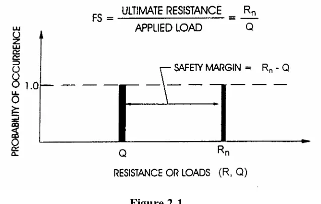
Figure 2-6
Empirical Rates of Failure for Civil Works Facilities (Kulhawy, et al., 1995)
A limit state is a condition beyond which a structural component, such as a foundation or other bridge component, ceases to fulfill the function for which it is designed. The limit states which must be evaluated in the AASHTO LRFD Specification (AASHTO, 1997a) include:
y Service Limit State y Strength Limit State y Extreme Limit State y Fatigue Limit State
The Service Limit State represents structure performance under service load conditions. Examples for substructure design include settlement of a foundation or lateral displacement of a retaining wall. Another example of a Service Limit State condition is presented in Figure 2-7 which shows the rotation of a rocker bearing on an abutment caused by instability of the earth slope which supported the abutment.
Figure 2-7
Example Condition for Service Limit State Evaluation
Figure 2-8
Example Condition for Strength Limit State Evaluation 2.4 LRFD Calibration
Calibration of the load and resistance factors is required to achieve the desired results when applying LRFD. Calibration procedures for selection of resistance factors are described fully in Chapters 3 and 7, but generally involve:
y Engineering judgment y Fitting to ASD
y Reliability theory
For the LRFD Specification, a combination of approaches was used in selecting resistance factors, φ, for design. In general, the resistance factors selected for most of the methods used for foundation design were developed principally using reliability-based calibration procedures where sufficient performance data were available (e.g., bearing resistance of footings and individual deep foundation elements). The value of φ chosen for a particular design procedure and limit state from a reliability-based calibration can take into account the:
y Variability of the soil and rock properties
y Reliability of the equations used for predicting resistance y Quality of the construction workmanship
y Extent of soil exploration y Consequence(s) of a failure
Where insufficient or no data were available to conduct a reliability-based calibration, resistance factors were selected primarily by fitting to ASD (e.g., eccentricity, anchored and MSE wall design) and judgment. Therefore, the principal benefit of LRFD, namely to achieve consistent levels of safety in component design, are not completely realized. The resistance factors incorporated in the LRFD Specification were checked by trial designs to confirm that the results are comparable to current ASD practice.
2.5 Summary
The incorporation of LRFD represents a significant step and major improvement in the processes of foundation, retaining wall and culvert design, as it permits design based primarily on a rational evaluation of performance reliability, rather than the judgment and experience of and individual designer (although the importance of these even in LRFD should not be minimized). As it is currently embodied in the AASHTO Specification, LRFD offers many advantages, primarily that it:
y Accounts separately for variability in load and resistance prediction
y Achieves more consistent levels of safety in structure and substructure design y Does not require knowledge of probability or reliability theory
On the other hand, LRFD does present a challenge to the practicing engineer, in that:
y Implementation requires a change for engineers accustomed to ASD y Resistance factors vary with design methods and are not constant
y Rigorous calibration of load and resistance factors to meet individual situations requires availability of statistical data and probabilistic design algorithms