LOAD AND RESISTANCE
FACTOR DESIGN
SPECIFICATION
For Structural
Steel Buildings
Load and
Resistance
Factor Design
Specification
for Structural Steel Buildings
December 27, 1999
Supersedes the
Load and Resistance Factor Design Specification
for Structural Steel Buildings
dated
December 1, 1993 and all previous versions.
Prepared by the American Institute of Steel Construction, Inc. Under the Direction of the AISC Committee on Specifications and approved by the AISC Board of Directors.
AMERICAN INSTITUTE OF STEEL CONSTRUCTION, INC.
Copyright © 2000 by
American Institute of Steel Construction, Inc.
All rights reserved. This book or any part thereof must not be reproduced in any form without the written permission of the publisher.
The information presented in this publication has been prepared in accordance with recognized engineering principles and is for general information only. While it is believed to be accurate, this information should not be used or relied upon for any specific application without competent professional examination and verification of its accuracy, suitability, and applicability by a licensed engineer, architect or other professional. The publication of the material contained herein is not intended as a representation or warranty on the part of the American Institute of Steel Construc-tion, Inc. or of any other person named herein, that this information is suitable for any general or particular use or of freedom from infringement of any patent or pat-ents. Anyone making use of this information assumes all liability arising from such use.
Caution must be exercised when relying upon other specifications and codes devel-oped by other bodies and incorporated by reference herein since such material may be modified or amended from time to time subsequent to the printing of this edition. The American Institute of Steel Construction, Inc. bears no responsibility for such material other than to refer to it and incorporate it by reference at the time of the initial publication of this edition.
Printed in the United States of America
PREFACE
The AISCLoad and Resistance Factor Design (LRFD) Specification for Structural Steel Buildingsis based on reliability theory. As have all AISC Specifications, this Specifica-tion has been based upon past successful usage, advances in the state of knowledge, and changes in design practice. This Specification has been developed as a consensus docu-ment to provide a uniform practice in the design of steel-framed buildings. The intention is to provide design criteria for routine use and not to provide specific criteria for infre-quently encountered problems, which occur in the full range of structural design. This Specification is the result of the consensus deliberations of a committee of structural engineers with wide experience and high professional standing, representing a wide geo-graphical distribution throughout the U.S. The committee includes approximately equal numbers of engineers in private practice and code agencies, engineers involved in research and teaching, and engineers employed by steel fabricating and producing com-panies. The contributions and assistance of more than 50 additional professional volun-teers working in 15 task committees are also hereby acknowledged.
The Symbols, Glossary, and Appendices to this Specification are an integral part of the Specification. A non-mandatory Commentary has been prepared to provide background for the Specification provisions and the user is encouraged to consult it.
The principal changes incorporated in this edition of the Specification include:
•Dual units format. Values and equations are given in both U.S. customary and metric units. The metric conversions (given in parentheses following the U.S. units) are based on ASTM E380,Standard Practice for Use of the International System of Units (SI). The equations are non-dimensionalized where possible by factoring out material constants, such asEandG.
•Inclusion of new structural steels ASTM A913 and A992.
•Additional notch toughness requirements for complete-joint-penetration groove welds with tension applied normal to the effective area.
•New provisions for stability bracing of beams, columns, and frames.
•New Chapter N for evaluation of existing structures.
•Revised provisions for member design under fatigue loading in Appendix K.
iii
•Reorganization of material on pin-connected members and eyebars.
•Revised provisions for concrete-encased beams.
•New limitation on the stud reduction factor when a single stud is used in a rib.
•Revised bolt bearing strength criteria.
The reader is cautioned that professional judgment must be exercised when data or recom-mendations in the Specification are applied, as described more fully in the disclaimer notice preceding this Preface.
By the Committee,
Stanley D. Lindsey, Chairman Nestor R. Iwankiw Roger E. Ferch, Vice Chairman Lawrence A. Kloiber Hansraj G. Ashar Roberto T. Leon William F. Baker H.S. Lew John M. Barsom James O. Malley Reidar Bjorhovde Richard W. Marshall Roger L. Brockenbrough Harry W. Martin Wai-Fah Chen William A. Milek Gregory G. Deierlein Duane K. Miller Robert O. Disque Thomas M. Murray Duane S. Ellifritt R. Shankar Nair Bruce R. Ellingwood Clarkson W. Pinkham Shu-Jin Fang Douglas D. Rees-Evans Steven J. Fenves Thomas Z. Scarangello James M. Fisher Donald R. Sherman John W. Fisher W. Lee Shoemaker Theodore V. Galambos Frank F. Sowokinos Lawrence G. Griffis William A. Thornton James R. Harris Raymond H. R. Tide Tony C. Hazel Ivan M. Viest Mark V. Holland Joseph A. Yura
Cynthia J. Lanz, Secretary
iv PREFACE
TABLE OF CONTENTS
SYMBOLS . . . . xv
GLOSSARY . . . . xxiii
SPECIFICATION A. GENERAL PROVISIONS. . . . 1
A1. Scope . . . . 1
A2. Types of Construction . . . . 1
A3. Material . . . . 2
1. Structural Steel . . . . 2
2. Steel Castings and Forgings . . . . 4
3. Bolts, Washers, and Nuts . . . . 4
4. Anchor Rods and Threaded Rods . . . . 5
5. Filler Metal and Flux for Welding . . . . 5
6. Stud Shear Connectors . . . . 6
A4. Loads and Load Combinations . . . . 6
A5. Design Basis . . . . 6
1. Required Strength at Factored Loads . . . . 6
2. Limit States . . . . 7
3. Design for Strength . . . . 7
4. Design for Serviceability and Other Considerations . . . . 7
A6. Referenced Codes and Standards . . . . 7
A7. Design Documents . . . . 8
B. DESIGN REQUIREMENTS. . . . 10
B1. Gross Area . . . . 10
B2. Net Area . . . . 10
B3. Effective Area of Tension Members . . . . 10
B4. Stability . . . . 11
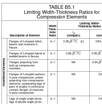
B5. Local Buckling . . . . 12
1. Classification of Steel Sections . . . . 12
2. Design by Plastic Analysis . . . . 13
3. Slender-Element Compression Sections . . . . 13
B6. Bracing at Supports . . . . 13
B7. Limiting Slenderness Ratios . . . . 13
B8. Simple Spans . . . . 13
B9. End Restraint . . . . 13
B10. Proportions of Beams and Girders . . . . 13
C. FRAMES AND OTHER STRUCTURES. . . . 17
C1. Second Order Effects. . . . 17
1. Design by Plastic Analysis . . . . 17
2. Design by Elastic Analysis . . . . 17
C2. Frame Stability . . . . 18
1. Braced Frames . . . . 18
2. Unbraced Frames . . . . 19
LRFD Specification for Structural Steel Buildings, December 27, 1999
SPECIFICATION (Cont’d)
C3. Stability Bracing . . . . 19
1. Scope . . . . 19
2. Frames . . . . 19
3. Columns . . . . 20
4. Beams . . . . 21
D. TENSION MEMBERS. . . . 24
D1. Design Tensile Strength . . . . 24
D2. Built-Up Members . . . . 24
D3. Pin-Connected Members and Eyebars . . . . 25
1. Pin-Connected Members . . . . 25
2. Eyebars . . . . 26
E. COLUMNS AND OTHER COMPRESSION MEMBERS. . . . 27
E1. Effective Length and Slenderness Limitations. . . . 27
1. Effective Length . . . . 27
2. Design by Plastic Analysis . . . . 27
E2. Design Compressive Strength for Flexural Buckling . . . . 27
E3. Design Compressive Strength for Flexural-Torsional Buckling . . . . 28
E4. Built-Up Members . . . . 28
1. Design Strength . . . . 28
2. Detailing Requirements . . . . 29
E5. Connections for Pin-Connected Compression Members . . . . 30
F. BEAMS AND OTHER FLEXURAL MEMBERS . . . . 31
F1. Design for Flexure . . . . 31
1. Yielding . . . . 31
2. Lateral-Torsional Buckling . . . . 32
3. Design by Plastic Analysis . . . . 34
F2. Design for Shear . . . . 35
1. Web Area Determination . . . . 35
2. Design Shear Strength. . . . 35
3. Transverse Stiffeners . . . . 36
F3. Web-Tapered Members . . . . 36
F4. Beams and Girders with Web Openings . . . . 36
G. PLATE GIRDERS . . . . 37
H. MEMBERS UNDER COMBINED FORCES AND TORSION. . . . 38
H1. Symmetric Members Subject to Bending and Axial Force . . . . 38
1. Doubly and Singly Symmetric Members in Flexure and Tension . . 38 2. Doubly and Singly Symmetric Members in Flexure and Compression. . . . 39
H2. Unsymmetric Members and Members Under Torsion and Combined Torsion, Flexure, Shear, and/or Axial Force . . . . 39
H3. Alternative Interaction Equations for Members Under Combined Stress (see Appendix H3) . . . . 39
I. COMPOSITE MEMBERS. . . . 40
I1. Design Assumptions and Definitions . . . . 40
I2. Compression Members. . . . 41
1. Limitations . . . . 41
LRFD Specification for Structural Steel Buildings, December 27, 1999
SPECIFICATION (Cont’d)
2. Design Strength . . . . 42
3. Columns with Multiple Steel Shapes . . . . 42
4. Load Transfer . . . . 43
I3. Flexural Members . . . . 43
1. Effective Width . . . . 43
2. Design Strength of Beams with Shear Connectors . . . . 43
3. Design Strength of Concrete-Encased Beams . . . . 44
4. Strength During Construction . . . . 44
5. Formed Steel Deck . . . . 44
6. Design Shear Strength. . . . 46
I4. Combined Compression and Flexure . . . . 46
I5. Shear Connectors. . . . 46
1. Materials. . . . 46
2. Horizontal Shear Force . . . . 46
3. Strength of Stud Shear Connectors . . . . 47
4. Strength of Channel Shear Connectors . . . . 47
5. Required Number of Shear Connectors . . . . 47
6. Shear Connector Placement and Spacing . . . . 48
I6. Special Cases. . . . 48
J. CONNECTIONS, JOINTS, AND FASTENERS . . . . 49
J1. General Provisions . . . . 49
1. Design Basis. . . . 49
2. Simple Connections . . . . 49
3. Moment Connections . . . . 49
4. Compression Members with Bearing Joints . . . . 49
5. Splices in Heavy Sections . . . . 49
6. Beam Copes and Weld Access Holes. . . . 50
7. Minimum Strength of Connections . . . . 50
8. Placement of Welds and Bolts . . . . 51
9. Bolts in Combination with Welds . . . . 51
10. High-Strength Bolts in Combination with Rivets . . . . 51
11. Limitations on Bolted and Welded Connections . . . . 51
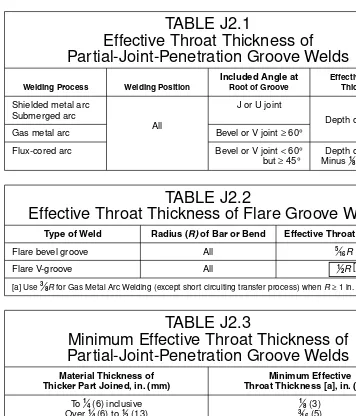
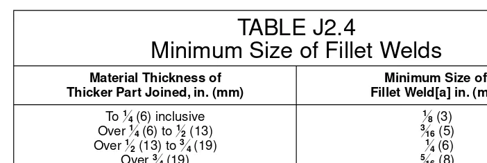
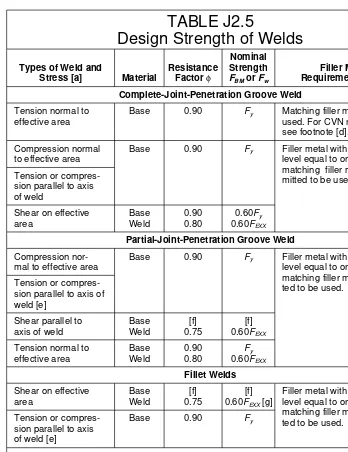
J2. Welds . . . . 52
1. Groove Welds . . . . 52
2. Fillet Welds . . . . 53
3. Plug and Slot Welds . . . . 56
4. Design Strength . . . . 56
5. Combination of Welds. . . . 58
6. Weld Metal Requirements . . . . 58
7. Mixed Weld Metal. . . . 58
8. Preheat for Heavy Shapes . . . . 58
J3. Bolts and Threaded Parts. . . . 58
1. High-Strength Bolts . . . . 58
2. Size and Use of Holes . . . . 59
3. Minimum Spacing . . . . 60
4. Minimum Edge Distance . . . . 60
5. Maximum Spacing and Edge Distance . . . . 60
6. Design Tension or Shear Strength . . . . 62
LRFD Specification for Structural Steel Buildings, December 27, 1999
SPECIFICATION (Cont’d)
7. Combined Tension and Shear in Bearing-Type Connections . . . . . 63
8. High-Strength Bolts in Slip-Critical Connections . . . . 64
9. Combined Tension and Shear in Slip-Critical Connections . . . . . 66
10. Bearing Strength at Bolt Holes . . . . 66
11. Long Grips . . . . 67
J4. Design Rupture Strength . . . . 67
1. Shear Rupture Strength . . . . 67
2. Tension Rupture Strength. . . . 67
3. Block Shear Rupture Strength. . . . 67
J5. Connecting Elements. . . . 68
1. Eccentric Connections. . . . 68
2. Design Strength of Connecting Elements in Tension . . . . 68
3. Other Connecting Elements . . . . 68
J6. Fillers . . . . 69
J7. Splices . . . . 69
J8. Bearing Strength . . . . 69
J9. Column Bases and Bearing on Concrete. . . . 70
J10. Anchor Rods and Embedments . . . . 70
K. CONCENTRATED FORCES, PONDING, AND FATIGUE. . . . 71
K1. Flanges and Webs with Concentrated Forces . . . . 71
1. Design Basis. . . . 71
2. Flange Local Bending . . . . 71
3. Web Local Yielding . . . . 72
4. Web Crippling . . . . 72
5. Web Sidesway Buckling. . . . 73
6. Web Compression Buckling . . . . 74
7. Web Panel-Zone Shear . . . . 75
8. Unframed Ends of Beams and Girders . . . . 76
9. Additional Stiffener Requirements for Concentrated Forces . . . . . 76
10. Additional Doubler Plate Requirements for Concentrated Forces . . 76 K2. Ponding . . . . 77
K3. Design for Cyclic Loading (Fatigue). . . . 77
L. SERVICEABILITY DESIGN CONSIDERATIONS. . . . 79
L1. Camber . . . . 79
L2. Expansion and Contraction . . . . 79
L3. Deflections, Vibration, and Drift . . . . 79
1. Deflections . . . . 79
2. Floor Vibration . . . . 79
3. Drift . . . . 79
L4. Connection Slip . . . . 80
L5. Corrosion . . . . 80
M. FABRICATION, ERECTION, AND QUALITY CONTROL . . . . 81
M1. Shop Drawings . . . . 81
M2. Fabrication . . . . 81
1. Cambering, Curving, and Straightening . . . . 81
2. Thermal Cutting . . . . 81
3. Planing of Edges . . . . 81
viii TABLE OF CONTENTS
SPECIFICATION (Cont’d)
4. Welded Construction . . . . 82
5. Bolted Construction . . . . 82
6. Compression Joints . . . . 82
7. Dimensional Tolerances . . . . 82
8. Finish of Column Bases . . . . 82
M3. Shop Painting . . . . 83
1. General Requirements . . . . 83
2. Inaccessible Surfaces . . . . 83
3. Contact Surfaces . . . . 83
4. Finished Surfaces . . . . 83
5. Surfaces Adjacent to Field Welds . . . . 83
M4. Erection . . . . 83
1. Alignment of Column Bases . . . . 83
2. Bracing . . . . 83
3. Alignment . . . . 84
4. Fit of Column Compression Joints and Base Plates . . . . 84
5. Field Welding . . . . 84
6. Field Painting . . . . 84
7. Field Connections . . . . 84
M5. Quality Control. . . . 84
1. Cooperation . . . . 84
2. Rejections . . . . 84
3. Inspection of Welding . . . . 85
4. Inspection of Slip-Critical High-Strength Bolted Connections . . . . 85
5. Identification of Steel . . . . 85
N. EVALUATION OF EXISTING STRUCTURES . . . . 86
N1. General Provisions . . . . 86
N2. Material Properties . . . . 86
1. Determination of Required Tests . . . . 86
2. Tensile Properties . . . . 86
3. Chemical Composition . . . . 86
4. Base Metal Notch Toughness . . . . 87
5. Weld Metal . . . . 87
6. Bolts and Rivets . . . . 87
N3. Evaluation by Structural Analysis . . . . 87
1. Dimensional Data . . . . 87
2. Strength Evaluation . . . . 87
3. Serviceability Evaluation . . . . 87
N4. Evaluation by Load Tests . . . . 88
1. Determination of Live Load Rating by Testing . . . . 88
2. Serviceability Evaluation . . . . 88
N5. Evaluation Report . . . . 88
APPENDIX B. DESIGN REQUIREMENTS . . . . 89
B5. Local Buckling . . . . 89
1. Classification of Steel Sections . . . . 89
3. Slender-Element Compression Sections . . . . 89
APPENDIX E. COLUMNS AND OTHER COMPRESSION MEMBERS . . . 94
LRFD Specification for Structural Steel Buildings, December 27, 1999
SPECIFICATION (Cont’d)
E3. Design Compressive Strength for Flexural-Torsional Buckling . . . . 94
APPENDIX F. BEAMS AND OTHER FLEXURAL MEMBERS. . . . 96
F1. Design for Flexure . . . . 96
F2. Design for Shear . . . . 102
2. Design Shear Strength . . . . 102
3. Transverse Stiffeners . . . . 102
F3. Web-Tapered Members . . . . 103
1. General Requirements . . . . 103
2. Design Tensile Strength . . . . 103
3. Design Compressive Strength . . . . 103
4. Design Flexural Strength. . . . 104
5. Design Shear Strength . . . . 106
6. Combined Flexure and Axial Force . . . . 106
APPENDIX G. PLATE GIRDERS. . . . 107
G1. Limitations . . . . 107
G2. Design Flexural Strength. . . . 107
G3. Design Shear Strength . . . . 109
G4. Transverse Stiffeners . . . . 110
G5. Flexure-Shear Interaction . . . . 111
APPENDIX H. MEMBERS UNDER COMBINED FORCES AND TORSION . . . . 112
H3. Alternative Interaction Equations for Members Under Combined Stress . . . . 112
APPENDIX J. CONNECTIONS, JOINTS, AND FASTENERS. . . . 115
J2. Welds . . . . 115
4. Design Strength . . . . 115
J3. Bolts and Threaded Parts . . . . 117
7. Combined Tension and Shear in Bearing-Type Connections . . . . 117
8. High-Strength Bolts in Slip-Critical Connections . . . . 117
9. Combined Tension and Shear in Slip-Critical Connections . . . . . 117
APPENDIX K. CONCENTRATED FORCES, PONDING, AND FATIGUE . 118 K2. Ponding . . . . 118
K3. Design for Cyclic Loading (Fatigue) . . . . 121
1. General . . . . 121
2. Calculation of Maximum Stresses and Stress Ranges . . . . 121
3. Design Stress Range . . . . 122
4. Bolts and Threaded Parts . . . . 124
5. Special Fabrication and Erection Requirements . . . . 124
NUMERICAL VALUES. . . . 140
COMMENTARY INTRODUCTION . . . . 163
A. GENERAL PROVISIONS . . . . 164
A1. Scope . . . . 164
A2. Types of Construction . . . . 164
x TABLE OF CONTENTS
COMMENTARY (Cont’d)
A3. Material . . . . 167
1. Structural Steel . . . . 167
3. Bolts, Washers, and Nuts . . . . 169
4. Anchor Rods and Threaded Rods . . . . 170
5. Filler Metal and Flux for Welding . . . . 170
A4. Loads and Load Combinations . . . . 171
A5. Design Basis . . . . 172
1. Required Strength at Factored Loads . . . . 172
2. Limit States . . . . 172
3. Design for Strength . . . . 172
4. Design for Serviceability and Other Considerations . . . . 176
B. DESIGN REQUIREMENTS . . . . 177
B2. Net Area . . . . 177
B3. Effective Area of Tension Members . . . . 177
B5. Local Buckling . . . . 179
B7. Limiting Slenderness Ratios . . . . 182
C. FRAMES AND OTHER STRUCTURES . . . . 184
C1. Second Order Effects . . . . 184
C2. Frame Stability . . . . 188
C3. Stability Bracing . . . . 195
1. Scope . . . . 195
3. Columns . . . . 198
4. Beams . . . . 199
D. TENSION MEMBERS . . . . 202
D1. Design Tensile Strength. . . . 202
D2. Built-Up Members . . . . 202
D3. Pin-Connected Members and Eyebars . . . . 202
E. COLUMNS AND OTHER COMPRESSION MEMBERS. . . . 203
E1. Effective Length and Slenderness Limitations. . . . 203
1. Effective Length . . . . 203
2. Design by Plastic Analysis . . . . 203
E2. Design Compressive Strength for Flexural Buckling. . . . 203
E3. Design Compressive Strength for Flexural-Torsional Buckling . . . . . 204
E4. Built-Up Members . . . . 205
F. BEAMS AND OTHER FLEXURAL MEMBERS. . . . 206
F1. Design for Flexure . . . . 206
1. Yielding . . . . 206
2. Lateral-Torsional Buckling . . . . 206
3. Design by Plastic Analysis. . . . 209
F2. Design for Shear . . . . 210
F4. Beams and Girders with Web Openings . . . . 210
H. MEMBERS UNDER COMBINED FORCES AND TORSION . . . . 212
H1. Symmetric Members Subject to Bending and Axial Force . . . . 212
H2. Unsymmetric Members and Members Under Torsion and Combined Torsion, Flexure, Shear, and/or Axial Force . . . . 213
TABLE OF CONTENTS xi
COMMENTARY (Cont’d)
I. COMPOSITE MEMBERS . . . . 214
I1. Design Assumptions and Definitions . . . . 214
I2. Compression Members . . . . 215
1. Limitations . . . . 215
2. Design Strength . . . . 216
3. Columns with Multiple Steel Shapes . . . . 216
4. Load Transfer . . . . 216
I3. Flexural Members . . . . 217
1. Effective Width . . . . 217
2. Design Strength of Beams with Shear Connectors . . . . 217
3. Design Strength of Concrete-Encased Beams . . . . 221
4. Strength During Construction . . . . 222
5. Formed Steel Deck . . . . 222
6. Design Shear Strength . . . . 225
I4. Combined Compression and Flexure . . . . 225
I5. Shear Connectors . . . . 226
1. Materials . . . . 226
2. Horizontal Shear Force . . . . 226
3. Strength of Stud Shear Connectors . . . . 227
4. Strength of Channel Shear Connectors . . . . 227
6. Shear Connector Placement and Spacing . . . . 227
I6. Special Cases . . . . 228
J. CONNECTIONS, JOINTS, AND FASTENERS . . . . 229
J1. General Provisions . . . . 229
5. Splices in Heavy Sections . . . . 229
8. Placement of Welds and Bolts . . . . 231
9. Bolts in Combination with Welds . . . . 231
10. High-Strength Bolts in Combination with Rivets . . . . 232
J2. Welds . . . . 232
1. Groove Welds . . . . 232
2. Fillet Welds . . . . 232
4. Design Strength . . . . 238
5. Combination of Welds . . . . 239
6. Weld Metal Requirements . . . . 239
7. Mixed Weld Metal . . . . 240
J3. Bolts and Threaded Parts . . . . 240
1. High-Strength Bolts . . . . 240
2. Size and Use of Holes . . . . 241
3. Minimum Spacing . . . . 241
4. Minimum Edge Distance . . . . 241
5. Maximum Spacing and Edge Distance . . . . 242
6. Design Tension or Shear Strength . . . . 242
7. Combined Tension and Shear in Bearing-Type Connections . . . . 243
8. High-Strength Bolts in Slip-Critical Connections . . . . 243
10. Bearing Strength at Bolt Holes . . . . 246
11. Long Grips . . . . 246
J4. Design Rupture Strength . . . . 246
J5. Connecting Elements . . . . 248
xii TABLE OF CONTENTS
COMMENTARY (Cont’d)
2. Design Strength of Connecting Elements in Tension . . . . 248
J6. Fillers . . . . 248
J8. Bearing Strength . . . . 248
J9. Column Bases and Bearing on Concrete . . . . 248
K. CONCENTRATED FORCES, PONDING, AND FATIGUE. . . . 249
K1. Flanges and Webs with Concentrated Forces . . . . 249
1. Design Basis . . . . 249
2. Flange Local Bending . . . . 249
3. Web Local Yielding . . . . 249
4. Web Crippling . . . . 250
5. Web Sidesway Buckling . . . . 250
6. Web Compression Buckling . . . . 251
7. Web Panel-Zone Shear . . . . 252
K2. Ponding . . . . 254
L. SERVICEABILITY DESIGN CONSIDERATIONS . . . . 257
L1. Camber . . . . 258
L2. Expansion and Contraction . . . . 258
L3. Deflections, Vibration, and Drift . . . . 258
1. Deflections . . . . 258
2. Floor Vibration . . . . 258
3. Drift . . . . 259
L5. Corrosion . . . . 259
M. FABRICATION, ERECTION, AND QUALITY CONTROL . . . . 260
M2. Fabrication . . . . 260
1. Cambering, Curving, and Straightening . . . . 260
2. Thermal Cutting . . . . 260
5. Bolted Construction . . . . 260
M3. Shop Painting . . . . 261
5. Surfaces Adjacent to Field Welds . . . . 261
M4. Erection . . . . 261
2. Bracing . . . . 261
4. Fit of Column Compression Joints and Base Plates . . . . 261
5. Field Welding . . . . 261
N. EVALUATION OF EXISTING STRUCTURES. . . . 262
N1. General Provisions . . . . 262
N2. Material Properties . . . . 262
1. Determination of Required Tests . . . . 262
2. Tensile Properties . . . . 262
4. Base Metal Notch Toughness . . . . 263
5. Weld Metal . . . . 263
6. Bolts and Rivets . . . . 263
N3. Evaluation by Structural Analysis . . . . 263
2. Strength Evaluation . . . . 263
N4. Evaluation by Load Tests . . . . 263
1. Determination of Live Load Rating by Testing . . . . 263
2. Serviceability Evaluation . . . . 264
N5. Evaluation Report. . . . 265
TABLE OF CONTENTS xiii
COMMENTARY (Cont’d)
APPENDIX B. DESIGN REQUIREMENTS. . . . 266
B5. Local Buckling . . . . 266
1. Classification of Steel Sections . . . . 266
APPENDIX E. COLUMNS AND OTHER COMPRESSION MEMBERS. . . 267
E3. Design Compressive Strength for Flexural-Torsional Buckling . . . . . 267
APPENDIX F. BEAMS AND OTHER FLEXURAL MEMBERS . . . . 268
F1. Design for Flexure . . . . 268
F3. Web-Tapered Members . . . . 268
1. General Requirements . . . . 268
3. Design Compressive Strength . . . . 269
4. Design Flexural Strength . . . . 270
APPENDIX G. PLATE GIRDERS . . . . 271
G2. Design Flexural Strength . . . . 271
APPENDIX H. MEMBERS UNDER COMBINED FORCES AND TORSION . . . . 272
H3. Alternative Interaction Equations for Members Under Combined Stress . . . . 272
APPENDIX J. CONNECTIONS, JOINTS, AND FASTENERS . . . . 273
J2. Welds . . . . 273
4. Design Strength . . . . 273
APPENDIX K. CONCENTRATED FORCES, PONDING, AND FATIGUE . 276 K3. Design for Cyclic Loading (Fatigue) . . . . 276
REFERENCES. . . . 279
SUPPLEMENTARY BIBLIOGRAPHY . . . . 290
LRFD Specification for Structural Steel Buildings, December 27, 1999
SYMBOLS
The section number in the right hand column refers to the section where the symbol is first used.
Symbol Definition Section
A Area of directly connected elements . . . . B3
AB Loaded area of concrete, in.2(mm2). . . . I2.4 Ab Nominal unthreaded body area of bolt or threaded
part, in.2
(mm2
) . . . . J3.6
Ac Area of concrete, in. 2
(mm2
) . . . . I2.2
Ac Area of concrete slab within effective width, in.2(mm2) . . . . I5.2 AD Area of an upset rod based on the major thread diameter,
in.2
(mm2
) . . . . J3.6
Ae Effective area, in. 2
(mm2
) . . . . B3
Af Area of the compression flange, in.2(mm2) . . . . App. F3 Afe Effective tension flange area, in.
2
(mm2
) . . . . B10
Afg Gross area of flange, in.2(mm2). . . . B10 Afn Net area of flange, in.
2
(mm2
). . . . B10
Ag Gross area, in.2(mm2) . . . . A5 Agt Gross area subject to tension, in.
2
(mm2
) . . . . J4.3
Agv Gross area subject to shear, in.2(mm2) . . . . J4.3 An Net area, in.
2
(mm2
) . . . . B2
Ant Net area subject to tension, in.2(mm2) . . . . J4.2 Anv Net area subject to shear, in.
2
(mm2
) . . . . J4.1
Apb Projected bearing area, in.2(mm2). . . . J8.1 Ar Area of reinforcing bars, in.
2
(mm2
). . . . I2.2
As Area of steel cross section, in.2(mm2) . . . . I2.2 Asc Cross-sectional area of stud shear connector, in.
2
(mm2
) . . . . I5.3
Asf Shear area on the failure path, in.2(mm2) . . . . D3 At Net tensile area, in.
2
(mm2
) . . . . App. K3
Aw Web area, in.2(mm2) . . . . F2.1 A1 Area of steel concentrically bearing on a concrete support,
in.2
(mm2
) . . . . J9
A2 Total cross-sectional area of a concrete support, in. 2
(mm2
) . . . . J9
B Factor for bending stress in tees and double angles . . . . F1.2
B Factor for bending stress in web-tapered members, in. (mm),
defined by Equations A-F3-8 through A-F3-11. . . . App. F3
B1, B2 Factors used in determiningMufor combined bending and axial
forces when first-order analysis is employed . . . . C1
CPG Plate-girder coefficient . . . . App. G2 Cb Bending coefficient dependent on moment gradient . . . . F1.2a Cf Constant based on stress category, given in Table A-K3.1 . . . . . App. K3.3 Cm Coefficient applied to bending term in interaction formula
for prismatic members and dependent on column curvature
caused by applied moments . . . . C1
Cm¢ Coefficient applied to bending term in interaction formula
for tapered members and dependent on axial stress at the
xv
small end of the member . . . . App. F3
Cp Ponding flexibility coefficient for primary member in a flat
roof . . . . K2
Cs Ponding flexibility coefficient for secondary member in a
flat roof . . . . K2
Cv Ratio of “critical” web stress, according to linear buckling
theory, to the shear yield stress of web material . . . . App. G3
Cw Warping constant, in.6(mm6) . . . . F1.2 D Outside diameter of circular hollow section, in. (mm) . . . . App. B5.3
D Dead load due to the weight of the structural elements and
permanent features on the structure; nominal dead load . . . . App. K2
D Factor used in Equation A-G4-2, dependent on the type of
transverse stiffeners used in a plate girder . . . . App. G4
E Modulus of elasticity of steel,E= 29,000 ksi (200 000 MPa) . . E2
E Earthquake load
Ec Modulus of elasticity of concrete, ksi (MPa) . . . . I2.2 Em Modified modulus of elasticity, ksi (MPa) . . . . I2.2 FBM Nominal strength of the base material to be welded, ksi (MPa) . . J2.4 FEXX Classification number of weld metal (minimum specified
strength), ksi (MPa) . . . . J2.4
FL Smaller of (Fyf−Fr) orFyw, ksi (MPa) . . . . F1.2 FSR Design stress range, ksi (MPa) . . . . App. K3.3 FTH Threshold fatigue stress range, maximum stress range for
indefinite design life, ksi (MPa) . . . . App. K3.3
Fbg Flexural stress for tapered members defined by Equations
A-F3-4 and A-F3-5 . . . . App. F3
Fcr Critical stress, ksi (MPa) . . . . E2 Fcrft,
Fcry,
Fcrz Flexural-torsional buckling stresses for double-angle
and tee-shaped compression members, ksi (MPa) . . . . E3
Fe Elastic buckling stress, ksi (MPa) . . . . App. E3 Fex Elastic flexural buckling stress about the major axis, ksi (MPa) . . App. E3 Fey Elastic flexural buckling stress about the minor axis, ksi (MPa) . . App. E3 Fez Elastic torsional buckling stress, ksi (MPa) . . . . App. E3 Fmy Modified yield stress for composite columns, ksi (MPa) . . . . I2.2 Fn Nominal shear rupture strength, ksi (MPa) . . . . J4 Fr Compressive residual stress in flange [10 ksi (69 MPa) for
rolled shapes; 16.5 ksi (114 MPa) for welded built-up shapes]. . . B5.1
Fsg Stress for tapered members defined by Equation A-F3-6,
ksi (MPa) . . . . App. F3
Fu Specified minimum tensile strength of the type of steel
being used, ksi (MPa) . . . . B10
Fw Nominal strength of the weld electrode material, ksi (MPa) . . . . J2.4 Fwg Stress for tapered members defined by Equation A-F3-7,
ksi (MPa) . . . . App. F3
Fy Specified minimum yield stress of the type of steel being
used, ksi (MPa). As used in this Specification, “yield stress” denotes either the specified minimum yield point (for those steels that have a yield point) or specified yield
xvi SYMBOLS
strength (for those steels that do not have a yield point) . . . . A5
Fyf Specified minimum yield stress of the flange, ksi (MPa) . . . . B5.1 Fyr Specified minimum yield stress of reinforcing bars,
ksi (MPa) . . . . I2.2
Fyst Specified minimum yield stress of the stiffener material,
ksi (MPa) . . . . App. G4
Fyw Specified minimum yield stress of the web, ksi (MPa) . . . . B5.1 G Shear modulus of elasticity of steel,G= 11,200 ksi
(77 200 MPa) . . . . F1.2
H Horizontal force, kips (N) . . . . C1
H Flexural constant . . . . E3
Hs Length of stud connector after welding, in. (mm) . . . . I3.5 I Moment of inertia, in.4
(mm4
) . . . . F1.2
Id Moment of inertia of the steel deck supported on secondary
members, in.4
(mm4
) . . . . K2
Ip Moment of inertia of primary members, in.4(mm4). . . . K2 Is Moment of inertia of secondary members, in.
4
(mm4
) . . . . K2
Ist Moment of inertia of a transverse stiffener, in.4(mm4) . . . . App. G4 Iyc Moment of inertia about y-axis referred to compression flange, or if
reverse curvature bending referred to smaller flange, in.4
(mm4
) . . App. F1
J Torsional constant for a section, in.4
(mm4
) . . . . F1.2
K Effective length factor for prismatic member . . . . B7
Kz Effective length factor for torsional buckling . . . . App. E3 Kg Effective length factor for a tapered member . . . . App. F3 L Story height or panel spacing, in. (mm). . . . C1
L Length of connection in the direction of loading, in. (mm). . . . . B3
L Live load due to occupancy and moveable equipment . . . . N4
Lb Laterally unbraced length; length between points which are either
braced against lateral displacement of compression flange or braced against twist of the cross section, in. (mm) . . . . F1.2
Lc Length of channel shear connector, in. (mm) . . . . I5.4 Lc Edge distance, in. (mm) . . . . J3.10 Lp Limiting laterally unbraced length for full plastic bending capacity,
uniform moment case (Cb= 1.0), in. (mm) . . . . F1.2 Lp Column spacing in direction of girder, ft (m) . . . . K2 Lpd Limiting laterally unbraced length for plastic analysis,
in. (m) . . . . F1.2
Lq Maximum unbraced length for the required column force with Kequal to one, in. (mm) . . . . C3
Lr Limiting laterally unbraced length for inelastic
lateral-torsional buckling, in. (mm). . . . F1.2
Lr Roof live load . . . . N4 Ls Column spacing perpendicular to direction of girder, ft (m) . . . . K2 MA Absolute value of moment at quarter point of the unbraced
beam segment, kip-in. (N-mm) . . . . F1.2
MB Absolute value of moment at centerline of the unbraced
beam segment, kip-in. (N-mm) . . . . F1.2
MC Absolute value of moment at three-quarter point of the
unbraced beam segment, kip-in. (N-mm) . . . . F1.2
Mcr Elastic buckling moment, kip-in. (N-mm) . . . . F1.2
SYMBOLS xvii
Mlt Required flexural strength in member due to lateral frame
translation only, kip-in. (N-mm) . . . . C1
Mmax Absolute value of maximum moment in the unbraced
beam segment, kip-in. (N-mm) . . . . F1.2
Mn Nominal flexural strength, kip-in. (N-mm) . . . . F1.1 M¢nx,
M¢ny Flexural strength defined in Equations A-H3-7 and A-H3-8 for use
in alternate interaction equations for combined bending and axial
force, kip-in. (N-mm) . . . . App. H3
Mnt Required flexural strength in member assuming there is no lateral
translation of the frame, kip-in. (N-mm) . . . . C1
Mp Plastic bending moment, kip-in. (N-mm) . . . . F1.1 Mp Moment defined in Equations A-H3-5 and A-H3-6, for use in
alternate interaction equations for combined bending and axial
force, kip-in. (N-mm) . . . . App. H3
Mr Limiting buckling moment,Mcr, whenl=lrandCb= 1.0, kip-in.
(N-mm) . . . . F1.2
Mu Required flexural strength, kip-in. (N-mm) . . . . C1 My Moment corresponding to onset of yielding at the extreme fiber
from an elastic stress distribution (=FySfor homogeneous
sections), kip-in. (N-mm) . . . . F1.1
M1 Smaller moment at end of unbraced length of beam or
beam-column, kip-in. (N-mm) . . . . F1.2
M2 Larger moment at end of unbraced length of beam or
beam-column, kip-in. (N-mm) . . . . F1.2
N Length of bearing, in. (mm). . . . K1.3
N Number of stress range fluctuations in design life . . . . App. K3.3
Nr Number of stud connectors in one rib at a beam intersection. . . . I3.5 Pbr Required story or panel bracing shear force, kip (N) . . . . C3 Pe1, Pe2 Elastic Euler buckling load for braced and unbraced frame,
respectively, kips (N) . . . . C1
Pn Nominal axial strength (tension or compression), kips (N). . . . . D1 Pp Bearing load on concrete, kips (N) . . . . J9 Pu Required axial strength (tension or compression), kips (N) . . . . B5.1 Py Yield strength, kips (N) . . . . B5.1 Q Full reduction factor for slender compression elements . . . . App. E3
Qa Reduction factor for slender stiffened compression elements . . . App. B5 Qn Nominal strength of one stud shear connector, kips (N) . . . . I5 Qs Reduction factor for slender unstiffened compression elements . . App. B5.3 R Nominal load due to initial rainwater or ice exclusive of the
ponding contribution . . . . N4
RPG Plate girder bending strength reduction factor . . . . App. G Re Hybrid girder factor . . . . App. F1 Rn Nominal strength . . . . A5.3 Rv Web shear strength, kips (N) . . . . K1.7 S Elastic section modulus, in.3
(mm3
) . . . . F1.2
S Spacing of secondary members, ft (m) . . . . K2
S Snow load . . . . N4
Sx¢ Elastic section modulus of larger end of tapered member about its
major axis, in.3
(mm3
) . . . . App. F3
xviii SYMBOLS
Seff Effective section modulus about major axis, in. 3
(mm3
) . . . . App. F1
Sxt,Sxc Elastic section modulus referred to tension and compression
flanges, respectively, in.3
(mm3
) . . . . App. F1
T Tension force due to service loads, kips (N) . . . . J3.9
Tb Specified pretension load in high-strength bolt, kips (N) . . . . J3.9 Tu Required tensile strength due to factored loads, kips (N). . . . J3.9 U Reduction coefficient, used in calculating effective net area . . . . B3
Vn Nominal shear strength, kips (N) . . . . F2.2 Vu Required shear strength, kips (N) . . . . App. G4 W Wind load . . . . Comm. A4
X1 Beam buckling factor defined by Equation F1-8 . . . . F1.2 X2 Beam buckling factor defined by Equation F1-9 . . . . F1.2 Z Plastic section modulus, in.3
(mm3
) . . . . F1.1
a Clear distance between transverse stiffeners, in. (mm). . . . App. F2.2
a Distance between connectors in a built-up member, in. (mm) . . . E4
a Shortest distance from edge of pin hole to edge of member
measured parallel to direction of force, in. (mm) . . . . D3
ar Ratio of web area to compression flange area . . . . App. G2 a¢ Weld length, in. (mm) . . . . B10
b Compression element width, in. (mm) . . . . B5.1
be Reduced effective width for slender compression elements,
in. (mm) . . . . App. B5.3
beff Effective edge distance, in. (mm) . . . . D3 bf Flange width, in. (mm) . . . . B5.1 bs Stiffener width for one-sided stiffeners, in. (mm) . . . . C3.4 c1,c2,c3Numerical coefficients . . . . I2.2 d Nominal fastener diameter, in. (mm) . . . . J3.3
d Overall depth of member, in. (mm) . . . . B5.1
d Pin diameter, in. (mm) . . . . D3
d Roller diameter, in. (mm) . . . . J8.2
dL Depth at larger end of unbraced tapered segment, in. (mm) . . . . App. F3 db Beam depth, in. (mm) . . . . K1.7 db Nominal diameter (body or shank diameter), in. (mm) . . . . App. K3.3 dc Column depth, in. (mm). . . . K1.7 do Depth at smaller end of unbraced tapered segment, in. (mm) . . . App. F3 e Base of natural logarithm = 2.71828. . . . . Comm. E2
f Computed compressive stress in the stiffened element, ksi (MPa) . App. B5.3
fb1 Smallest computed bending stress at one end of a tapered
segment, ksi (MPa) . . . . App. F3
fb2 Largest computed bending stress at one end of a tapered
segment, ksi (MPa) . . . . App. F3
fc¢ Specified compressive strength of concrete, ksi (MPa) . . . . I2.2 fo Stress due to 1.2D+ 1.2R, ksi (MPa) . . . . App. K2 fun Required normal stress, ksi (MPa) . . . . H2 fuv Required shear stress, ksi (MPa) . . . . H2 fv Required shear stress due to factored loads in bolts or rivets,
ksi (MPa) . . . . J3.7
g Transverse center-to-center spacing (gage) between fastener
gage lines, in. (mm) . . . . B2
h Clear distance between flanges less the fillet or corner radius for
LRFD Specification for Structural Steel Buildings, December 27, 1999
rolled shapes; and for built-up sections, the distance between adjacent lines of fasteners or the clear distance between flanges
when welds are used, in. (mm) . . . . B5.1
h Distance between centroids of individual components perpendicular to the member axis of buckling, in. (mm). . . . E4
hc Twice the distance from the centroid to the following: the inside
face of the compression flange less the fillet or corner radius, for rolled shapes; the nearest line of fasteners at the compression flange or the inside faces of the compression flange when welds are used, for built-up sections, in. (mm) . . . . B5.1
ho Distance between flange centroids, in. (mm) . . . . C3 hr Nominal rib height, in. (mm) . . . . I3.5 hs Factor used in Equation A-F3-6 for web-tapered members. . . . . App. F3 hw Factor used in Equation A-F3-7 for web-tapered members. . . . . App. F3 j Factor defined by Equation A-F2-4 for minimum moment of
inertia for a transverse stiffener . . . . App. F2.3
k Distance from outer face of flange to web toe of fillet, in. (mm) . . K1.3
kv Web plate buckling coefficient . . . . App. F2.2 l Laterally unbraced length of member at the point of load, in. (mm) B7
l Length of bearing, in. (mm). . . . J8.2
l Length of connection in the direction of loading, in. (mm). . . . . B3
l Length of weld, in. (mm) . . . . B3
m Ratio of web to flange yield stress or critical stress in hybrid
beams . . . . App. G2
n Number of nodal braced points within the span . . . . C3
n Threads per inch (per mm) . . . . App. K3.4
r Governing radius of gyration, in. (mm) . . . . B7
rTo For the smaller end of a tapered member, the radius of gyration,
considering only the compression flange plus one-third of the compression web area, taken about an axis in the plane of the web,
in. (mm) . . . . App. F3.4
ri Minimum radius of gyration of individual component in a built-up
member, in. (mm) . . . . E4
rib Radius of gyration of individual component relative to centroidal
axis parallel to member axis of buckling, in. (mm) . . . . E4
rm Radius of gyration of the steel shape, pipe, or tubing in composite
columns. For steel shapes it may not be less than 0.3 times the overall thickness of the composite section, in. (mm) . . . . I2
ro Polar radius of gyration about the shear center, in. (mm). . . . E3
rox,roy Radius of gyration about x and y axes at the smaller end of a
tapered member, respectively, in. (mm) . . . . App. F3.3
rx,ry Radius of gyration about x and y axes, respectively, in. (mm) . . . E3 ryc Radius of gyration about y axis referred to compression flange, or
if reverse curvature bending, referred to smaller flange, in. (mm) . App. F1
s Longitudinal center-to-center spacing (pitch) of any two consecutive holes, in. (mm) . . . . B2
t Thickness of element, in. (mm) . . . . B5.1
t HSS design wall thickness, in. (mm) . . . . B5.1
tf Flange thickness, in. (mm) . . . . B5.1 tf Flange thickness of channel shear connector, in. (mm) . . . . I5.4
LRFD Specification for Structural Steel Buildings, December 27, 1999
ts Web stiffener thickness, in. (mm) . . . . C3.4 tw Web thickness of channel shear connector, in. (mm) . . . . I5.4 tw Web thickness, in. (mm) . . . . B5.3 w Leg size of the fillet weld, in. (mm). . . . J2.2
w Plate width; distance between welds, in. (mm) . . . . B3
w Unit weight of concrete, lbs/cu ft. (kg/m3
) . . . . I2
wr Average width of concrete rib or haunch, in. (mm) . . . . I3.5 x Subscript relating symbol to member strong axis
xo,yo Coordinates of the shear center with respect to the centroid,
in. (mm) . . . . E3
x Connection eccentricity, in. (mm). . . . B3
y Subscript relating symbol to member weak axis
z Distance from the smaller end of tapered member used in
Equation A-F3-1 for the variation in depth, in. (mm). . . . App. F3
z Subscript relating symbol to member longitudinal axis
a Separation ratio for built-up compression members =h/ 2rib . . . E4 b Reduction factor given by Equation J2-1 . . . . J2 bT Brace stiffness requirement when there is no web
distortion . . . . C3.4 bTb Required nodal torsional bracing stiffness . . . . C3.4
bbr Required story or panel shear stiffness . . . . C3
bsec Web distortional stiffness, including the effect of web transverse
stiffeners, if any . . . . C3.4 Doh Translation deflection of the story under consideration,
in. (mm) . . . . C1 g Depth tapering ratio . . . . App. F3 g Subscript for tapered members . . . . App. F3 z Exponent for alternate beam-column interaction equation . . . . . App. H3 h Exponent for alternate beam-column interaction equation . . . . . App. H3 lc Column slenderness parameter . . . . C1
le Equivalent slenderness parameter . . . . App. E3
leff Effective slenderness ratio defined by Equation A-F3-2 . . . . App. F3
lp Limiting slenderness parameter for compact element . . . . B5.1
lr Limiting slenderness parameter for noncompact element . . . . . B5.1
f Resistance factor . . . . A5.3 fb Resistance factor for flexure . . . . F1
fc Resistance factor for compression . . . . A5.1
fc Resistance factor for axially loaded composite columns . . . . I2.2
fsf Resistance factor for shear on the failure path . . . . D3
ft Resistance factor for tension . . . . D1
fv Resistance factor for shear . . . . F2.2
SYMBOLS xxi
LRFD Specification for Structural Steel Buildings, December 27, 1999
GLOSSARY
Alignment chart for columns.A nomograph for determining the effective length factorK
for some types of columns
Amplification factor.A multiplier of the value of moment or deflection in the unbraced length of an axially loaded member to reflect the secondary values generated by the eccentricity of the applied axial load within the member
Aspect ratio.In any rectangular configuration, the ratio of the lengths of the sides
Batten plate.A plate element used to join two parallel components of a built-up column, girder, or strut rigidly connected to the parallel components and designed to transmit shear between them
Beam.A structural member whose primary function is to carry loads transverse to its lon-gitudinal axis
Beam-column.A structural member whose primary function is to carry loads both trans-verse and parallel to its longitudinal axis
Bent.A plane framework of beam or truss members which support loads and the columns which support these members
Biaxial bending.Simultaneous bending of a member about two perpendicular axes
Bifurcation.The phenomenon whereby a perfectly straight member under compression may either assume a deflected position or may remain undeflected, or a beam under flexure may either deflect and twist out of plane or remain in its in-plane deflected posi-tion
Braced frame.A frame in which the resistance to lateral load or frame instability is pri-marily provided by a diagonal, aKbrace, or other auxiliary system of bracing
Brittle fracture.Abrupt cleavage with little or no prior ductile deformation
Buckling load.The load at which a perfectly straight member under compression assumes a deflected position
Built-up member.A member made of structural metal elements that are welded, bolted, or riveted together
Charpy V-notch impact test. A standard dynamic test in which a notched specimen is struck and broken by a single blow in a specially designed testing machine. The mea-sured test values may be the energy absorbed, the percentage shear fracture, the lateral expansion opposite the notch, or a combination thereof
Cladding.The exterior covering of the structural components of a building
Cold-formed members.Structural members formed from steel without the application of heat
Column.A structural member whose primary function is to carry loads parallel to its lon-gitudinal axis
xxiii
Column curve.A curve expressing the relationship between axial column strength and slenderness ratio
Combined mechanism.A mechanism determined by plastic analysis procedure which combines elementary beam, panel, and joint mechanisms
Compact section.Compact sections are capable of developing a fully plastic stress distri-bution and possess rotation capacity of approximately three before the onset of local buckling
Composite beam.A steel beam structurally connected to a concrete slab so that the beam and slab respond to loads as a unit
Concrete-encased beam.A beam totally encased in concrete cast integrally with the slab
Connection.Combination of joints used to transmit forces between two or more mem-bers. Categorized by the type and amount of force transferred (moment, shear, end reaction). See alsoSplices
Critical load.The load at which bifurcation occurs as determined by a theoretical stability analysis
Curvature.Rotation per unit length due to bending
Design documents. Documents prepared by the designer (design drawings, design details, and job specifications)
Design strength.Resistance (force, moment, stress, as appropriate) provided by element or connection; the product of the nominal strength and the resistance factor
Diagonal bracing.Inclined structural members carrying primarily axial load enabling a structural frame to act as a truss to resist horizontal loads
Diaphragm.Floor slab, metal wall, or roof panel possessing a large in-plane shear stiff-ness and strength adequate to transmit horizontal forces to resisting systems
Diaphragm action.The in-plane action of a floor system (also roofs and walls) such that all columns framing into the floor from above and below are maintained in the same position relative to each other
Double concentrated forces.Two equal and opposite forces which form a couple on the same side of the loaded member
Double curvature.A bending condition in which end moments on a member cause the member to assume an S shape
Drift.Lateral deflection of a building
Drift index.The ratio of lateral deflection to the height of the building
Ductility factor.The ratio of the total deformation at maximum load to the elastic-limit deformation
Effective length.The equivalent lengthKLused in compression formulas and determined by a bifurcation analysis
Effective length factor K.The ratio between the effective length and the unbraced length of the member measured between the centers of gravity of the bracing members
LRFD Specification for Structural Steel Buildings, December 27, 1999
Effective moment of inertia.The moment of inertia of the cross section of a member that remains elastic when partial plastification of the cross section takes place, usually under the combination of residual stress and applied stress. Also, the moment of inertia based on effective widths of elements that buckle locally. Also, the moment of inertia used in the design of partially composite members
Effective stiffness.The stiffness of a member computed using the effective moment of inertia of its cross section
Effective width.The reduced width of a plate or slab which, with an assumed uniform stress distribution, produces the same effect on the behavior of a structural member as the actual plate width with its nonuniform stress distribution
Elastic analysis.Determination of load effects (force, moment, stress, as appropriate) on members and connections based on the assumption that material deformation disap-pears on removal of the force that produced it
Elastic-perfectly plastic.A material which has an idealized stress-strain curve that varies linearly from the point of zero strain and zero stress up to the yield point of the material, and then increases in strain at the value of the yield stress without any further increases in stress
Embedment.A steel component cast in a concrete structure which is used to transmit externally applied loads to the concrete structure by means of bearing, shear, bond, fric-tion, or any combination thereof. The embedment may be fabricated of structural-steel plates, shapes, bars, bolts, pipe, studs, concrete reinforcing bars, shear connectors, or any combination thereof
Encased steel structure.A steel-framed structure in which all of the individual frame members are completely encased in cast-in-place concrete
Euler formula.The mathematical relationship expressing the value of the Euler load in terms of the modulus of elasticity, the moment of inertia of the cross section, and the length of a column
Euler load.The critical load of a perfectly straight, centrally loaded pin-ended column
Eyebar.A particular type of pin-connected tension member of uniform thickness with forged or flame-cut head of greater width than the body proportioned to provide approximately equal strength in the head and body
Factored load.The product of the nominal load and a load factor
Fastener.Generic term for welds, bolts, rivets, or other connecting device
Fatigue.A fracture phenomenon resulting from a fluctuating stress cycle
First-order analysis.Analysis based on first-order deformations in which equilibrium conditions are formulated on the undeformed structure
Flame-cut plate.A plate in which the longitudinal edges have been prepared by oxygen cutting from a larger plate
Flat width.For a rectangular HSS, the nominal width minus twice the outside corner radius. In absence of knowledge of the corner radius, the flat width may be taken as the total section width minus three times the thickness
LRFD Specification for Structural Steel Buildings, December 27, 1999
Flexible connection.A connection permitting a portion, but not all, of the simple beam rotation of a member end
Floor system.The system of structural components separating the stories of a building
Force.Resultant of distribution of stress over a prescribed area. A reaction that develops in a member as a result of load (formerly called total stress or stress). Generic term sig-nifying axial loads, bending moment, torques, and shears
Fracture toughness.Measure of the ability to absorb energy without fracture. Generally determined by impact loading of specimens containing a notch having a prescribed geometry
Frame buckling.A condition under which bifurcation may occur in a frame
Frame instability. A condition under which a frame deforms with increasing lateral deflection under a system of increasing applied monotonic loads until a maximum value of the load called the stability limit is reached, after which the frame will continue to deflect without further increase in load
Fully composite beam.A composite beam with sufficient shear connectors to develop the full flexural strength of the composite section
High-cycle fatigue.Failure resulting from more than 20,000 applications of cyclic stress
HSS.Hollow structural sections that are prismatic square, rectangular or round products of a pipe or tubing mill and meet the geometric tolerance, tensile strength and chemical composition requirements of a standard specification
Hybrid beam.A fabricated steel beam composed of flanges with a greater yield strength than that of the web. Whenever the maximum flange stress is less than or equal to the web yield stress the girder is considered homogeneous
Hysteresis loop.A plot of force versus displacement of a structure or member subjected to reversed, repeated load into the inelastic range, in which the path followed during release and removal of load is different from the path for the addition of load over the same range of displacement
Inclusions.Nonmetallic material entrapped in otherwise sound metal
Incomplete fusion.Lack of union by melting of filler and base metal over entire prescribed area
Inelastic action.Material deformation that does not disappear on removal of the force that produced it
Instability.A condition reached in the loading of an element or structure in which contin-ued deformation results in a decrease of load-resisting capacity
Joint.Area where two or more ends, surfaces, or edges are attached. Categorized by type of fastener or weld used and method of force transfer
K bracing.A system of struts used in a braced frame in which the pattern of the struts resembles the letter K, either normal or on its side
Lamellar tearing.Separation in highly restrained base metal caused by through-thickness strains induced by shrinkage of adjacent filler metal
LRFD Specification for Structural Steel Buildings, December 27, 1999
Lateral bracing member.A member utilized individually or as a component of a lateral bracing system to prevent buckling of members or elements and/or to resist lateral loads
Lateral (or lateral-torsional) buckling.Buckling of a member involving lateral deflection and twist
Leaning column.Gravity-loaded column where connections to the frame (simple connec-tions) do not provide resistance to lateral loads
Limit state.A condition in which a structure or component becomes unfit for service and is judged either to be no longer useful for its intended function (serviceability limit state) or to be unsafe (strength limit state)
Limit states.Limits of structural usefulness, such as brittle fracture, plastic collapse, excessive deformation, durability, fatigue, instability, and serviceability
Load factor.A factor that accounts for unavoidable deviations of the actual load from the nominal value and for uncertainties in the analysis that transforms the load into a load effect
Loads.Forces or other actions that arise on structural systems from the weight of all per-manent construction, occupants and their possessions, environmental effects, differen-tial settlement, and restrained dimensional changes.Permanentloads are those loads in which variations in time are rare or of small magnitude. All other loads arevariable
loads. SeeNominal loads
LRFD (Load and Resistance Factor Design).A method of proportioning structural com-ponents (members, connectors, connecting elements, and assemblages) such that no applicable limit state is exceeded when the structure is subjected to all appropriate load combinations
Local buckling.The buckling of a compression element which may precipitate the failure of the whole member
Low-cycle fatigue.Fracture resulting from a relatively high-stress range resulting in a rel-atively small number of cycles to failure
Lower bound load.A load computed on the basis of an assumed equilibrium moment dia-gram in which the moments are not greater thanMpthat is less than or at best equal to
the true ultimate load
Mechanism.An articulated system able to deform without an increase in load, used in the special sense that the linkage may include real hinges or plastic hinges, or both
Mechanism method.A method of plastic analysis in which equilibrium between external forces and internal plastic hinges is calculated on the basis of an assumed mechanism. The failure load so determined is an upper bound
Nodal Brace. A brace that prevents the lateral movement or twist at the particular brace location along the length of the beam or column without any direct attachment to other braces at adjacent brace points. (See relative brace)
Nominal loads.The magnitudes of the loads specified by the applicable code
Nominal strength.The capacity of a structure or component to resist the effects of loads,
LRFD Specification for Structural Steel Buildings, December 27, 1999
as determined by computations using specified material strengths and dimensions and formulas derived from accepted principles of structural mechanics or by field tests or laboratory tests of scaled models, allowing for modeling effects and differences between laboratory and field conditions
Noncompact section.Noncompact sections can develop the yield stress in compression elements before local buckling occurs, but will not resist inelastic local buckling at strain levels required for a fully plastic stress distribution
P-Delta effect. Secondary effect of column axial loads and lateral deflection on the moments in members
Panel zone.The zone in a beam-to-column connection that transmits moment by a shear panel
Partially composite beam.A composite beam for which the shear strength of shear con-nectors governs the flexural strength
Plane frame.A structural system assumed for the purpose of analysis and design to be two-dimensional
Plastic analysis.Determination of load effects (force, moment, stress, as appropriate) on members and connections based on the assumption of rigid-plastic behavior, i.e., that equilibrium is satisfied throughout the structure and yield is not exceeded anywhere. Second order effects may need to be considered
Plastic design section.The cross section of a member which can maintain a full plastic moment through large rotations so that a mechanism can develop; the section suitable for design by plastic analysis
Plastic hinge. A yielded zone which forms in a structural member when the plastic moment is attained. The beam is assumed to rotate as if hinged, except that it is restrained by the plastic momentMp
Plastic-limit load.The maximum load that is attained when a sufficient number of yield zones have formed to permit the structure to deform plastically without further increase in load. It is the largest load a structure will support, when perfect plasticity is assumed and when such factors as instability, second-order effects, strain hardening, and frac-ture are neglected
Plastic mechanism.SeeMechanism
Plastic modulus.The section modulus of resistance to bending of a completely yielded cross section. It is the combined static moment about the plastic neutral axis of the cross-sectional areas above and below that axis
Plastic moment.The resisting moment of a fully-yielded cross section
Plastic strain.The difference between total strain and elastic strain
Plastic zone.The yielded region of a member
Plastification.The process of successive yielding of fibers in the cross section of a mem-ber as bending moment is increased
Plate girder.A built-up structural beam
LRFD Specification for Structural Steel Buildings, December 27, 1999
Post-buckling strength.The load that can be carried by an element, member, or frame after buckling
Prying Action. Lever action that exists in connections in which the line of application of the applied load is eccentric to the axis of the bolt, causing deformation of the fitting and an amplification of the axial force in the bolt
Redistribution of moment.A process which results in the successive formation of plastic hinges so that less highly stressed portions of a structure may carry increased moments
Relative Brace.A brace that controls the relative movement of two adjacent brace points along the length of a beam or column or the relative lateral displacement of two stories in a frame. (See nodal brace)
Required strength.Load effect (force, moment, stress, as appropriate) acting on element or connection determined either by structural analysis from the factored loads (using appropriate critical load combinations) or explicitly specified
Residual stress.The stresses that remain in an unloaded member after it has been formed into a finished product. (Examples of such stresses include, but are not limited to, those induced by cold bending, cooling after rolling, or welding)
Resistance.The capacity of a structure or component to resist the effects of loads. It is determined by computations using specified material strengths, dimensions and for-mulas derived from accepted principles of structural mechanics, or by field tests or lab-oratory tests of scaled models, allowing for modeling effects and differences between laboratory and field conditions. Resistance is a generic term that includes both strength and serviceability limit states
Resistance factor.A factor that accounts for unavoidable deviations of the actual strength from the nominal value and the manner and consequences of failure
Rigid frame.A structure in which connections maintain the angular relationship between beam and column members under load
Root of the flange.Location on the web of the corner radius termination point or the toe of the flange-to-web weld. Measured as thekdistance from the far side of the flange
Rotation capacity.The incremental angular rotation that a given shape can accept prior to local failure defined asR= (qu/qp) wherequis the overall rotation attained at the
fac-tored load state andqpis the idealized rotation corresponding to elastic theory applied
to the case ofM=Mp
St. Venant torsion.That portion of the torsion in a member that induces only shear stresses in the member
Second-order analysis.Analysis based on second-order deformations, in which equilib-rium conditions are formulated on the deformed structure
Service load.Load expected to be supported by the structure under normal usage; often taken as the nominal load
Serviceability limit state.Limiting condition affecting the ability of a structure to preserve its appearance, maintainability, durability, or the comfort of its occupants or function of machinery under normal usage
GLOSSARY xxix
Shape factor.The ratio of the plastic moment to the yield moment, or the ratio of the plas-tic modulus to the section modulus for a cross section
Shear friction.Friction between the embedment and the concrete that transmits shear loads. The relative displacement in the plane of the shear load is considered to be resisted by shear-friction anchors located perpendicular to the plane of the shear load
Shear lugs.Plates, welded studs, bolts, and other steel shapes that are embedded in the concrete and located transverse to the direction of the shear force and that transmit shear loads, introduced into the concrete by local bearing at the shear lug-concrete interface
Shear wall.A wall that resists, in its own plane, shear forces resulting from applied wind, earthquake, or other transverse loads or provides frame stability. Also called a struc-tural wall
Sidesway.The lateral movement of a structure under the action of lateral loads, unsym-metrical vertical loads, or unsymunsym-metrical properties of the structure
Sidesway buckling.The buckling mode of a multistory frame precipitated by the relative lateral displacements of joints, leading to failure by sidesway of the frame
Simple plastic theory.SeePlastic design
Single curvature.A deformed shape of a member having one smooth continuous arc, as opposed to double curvature which contains a reversal
Slender-element section.The cross section of a member which will experience local buckling in the elastic range
Slenderness ratio.The ratio of the effective length of a column to the radius of gyration of the column, both with respect to the same axis of bending
Slip-critical joint.A bolted joint in which the slip resistance of the connection is required
Space frame.A three-dimensional structural framework (as contrasted to a plane frame)
Splice.The connection between two structural elements joined at their ends to form a sin-gle, longer element
Stability-limit load. Maximum (theoretical) load a structure can support when sec-ond-order instability effects are included
Stepped column.A column with changes from one cross section to another occurring at abrupt points within the length of the column
Stiffener.A member, usually an angle or plate, attached to a plate or web of a beam or girder to distribute load, to transfer shear, or to prevent buckling