Received date 2016-02-05, Revised date 2016-03-03, Accepted date 2016-03-04 DOI : 10.20449/jnte.v5i1.192
APPLICATION OF GENETIC ALGORITHM TO MINIMIZE
HARMONIC IN MULTILEVEL INVERTER
Firmansyah Nur Budiman
1*, Novie Ayub Windarko
2, Son Kuswadi
31Jurusan Teknik Elektro, Fakultas Teknologi Industri, Universitas Islam Indonesia 2Teknik Elektro Industri, Departemen Teknik Elektro, Politeknik Elektronika Negeri Surabaya
3Teknik Mekatronika, Departemen Teknik Mekanika dan Energi,
Politeknik Elektronika Negeri Surabaya
*Corresponding author, e-mail: [email protected]
Abstrak—Dalam desain inverter, harmonisa tegangan merupakan permasalahan utama yang mempengaruhi performa inverter. Pada umumnya, kompleksitas permasalahan minimisasi harmonisa dipengaruhi oleh jumlah orde harmonisa yang akan diminimisasi. Paper ini membahas utilisasi algoritman genetika untuk menyelesaikan persoalan minimisasi harmonisa di inverter multilevel. Tujuannya adalah
untuk menemukan hubungan antara jumlah orde harmonisa yang diminimisasi dan total harmonic
distortion (THD) yang dihasilkan. Inverter yang diinvestigasi adalah inverter 11-level, akan tetapi studi ini bisa diaplikasikan ke inverter multilevel dengan jumlah level yang lain. Hasil studi menunjukkan bahwa harmonisa di tegangan keluaran inverter memiliki keterkaitan yang kecil terhadap jumlah orde harmonisa yang diminimisasi. Akan tetapi, hasil yang paling bagus tetap masih didapatkan ketika jumlah harmonisa yang diminimisasi banyak. THD terbaik yang diperoleh, dievaluasi hingga harmonisa ke-19, adalah 2,76%, dimana angka ini cukup kecil dan dapat diterima.
Kata Kunci : Harmonisa, algoritma genetika, inverter multilevel dan optimisasi
Abstract—In inverter design, harmonic voltage is the main issue which affects the performance of the inverter. Generally, the harmonic minimization problem complexity is influenced by the number of harmonic orders to be minimized. This paper presents the utilization of genetic algorithm (GA) to solve harmonic minimization problem in multilevel inverter. The objective is to find relationship between the number of minimized harmonic orders and the results of total harmonic distortion (THD). The inverter to investigate is 11-level, but it is also applicable to multilevel inverters with any number of levels. The results show that harmonic contained in the output voltage has a small dependence on the number of harmonic orders that are minimized. However, the best results are still satisfied even though involving higher number
of harmonics. The best-obtained THD, evaluated until 19th harmonic, is 2.76%, which is fairly low and thus
acceptable.
Keywords : Harmonic, genetic algorithm, multilevel inverter and optimization.
Copyright © 2016 JNTE. All rights reserved
1. INTRODUCTION
Inverters play vital roles in power grid with penetration of renewable energy systems. They produce AC voltage from DC voltage generated by several renewable energy converters, such as photovoltaic [1]. This photovoltaic can directly be connected to AC main grid or be connected to DC bus first, together with other DC voltage producers, and then connected to AC main grid through an inverter [2].
Special type inverter that involves several two-level inverters arranged together is called multilevel inverters. These inverters have
74
Jurnal Nasional Teknik Elektro
Instead of producing square-wave output asthe conventional two-level inverters do, multilevel inverters output waveforms are in a stepped form (more like sinusoidal waveform), which results in lower harmonics. However, the harmonics need to be minimized further in order to satisfy maximum criterion for THD, e.g. 5 % according IEEE standard for THD of current [7]. The widely-used methods to control the output voltage of multilevel inverters include various multilevel sinusoidal PWM and space-vector PWM [8] - [9], but they increase control complexity and switching frequency. Another technique is called selective harmonic elimination (SHE) or programmed PWM [10].
Solving SHE problem using soft computation techniques have been becoming popular nowadays as compared to calculus-based method. The main advantage of soft computation techniques is their capability of solving linear mathematical problems in a non-conventional way [11]. The availability of soft computation built-in tools in several softwares even makes it easier to utilize soft computation techniques to solve engineering problems.
In this paper, one of the most popular soft computation techniques, called genetic algorithm (GA), is used to minimize low-order harmonics in multilevel inverter until certain limits. The contribution of this study is an investigation resulting in a knowledge about the relationship between number of harmonics that are minimized and the THD. It is shown that in most cases, the number of minimized harmonic orders indeed determines the THD of the output voltage. However, the relationship is not strictly linear, in the sense that higher number of minimized harmonic orders does not always guarantee lower THD. Thus, it is worth to consider the targeted THD when designing the inverter. If the THD is required to be as small as possible, then minimization of higher number of harmonic orders scheme can be used. On the other hand, if the THD is only required to be less than a certain value, e.g. 5%, it is not always necessary to employ such a scheme.
2. MULTILEVEL INVERTER
The most-commonly used multilevel inverter is series connection of several H-bridge inverter units. Each unit is powered by an independent DC source, which may be battery, super
capacitor, fuel cell, solar cell, etc. In this paper, a single-phase 11-level inverter, whose structure and output voltage waveform are shown in Fig.1, is employed to perform study. This study only considers multilevel inverter with equal DC sources. The output voltage of the inverter v0 is the sum of H-bridge voltages, i.e. v0 = v1 + v2 +
v3 + v4 + v5. Each inverter unit is able to generate three voltage levels, i.e. +Vdc, 0, and –Vdc, depending on the state of its four switching devices. The level number of the inverter output voltage m is given by m = 2s + 1, where s is the number of DC sources. Thus, an 11-level inverter has 5 independent DC sources, as clearly shown by Fig. 1.
(a) Structure
(b) Output voltage waveform
Figure 1. (a) The structure and (b) output voltage waveform of a single-phase 11-level
Jurnal Nasional Teknik Elektro
75
The Fourier expansion of the output voltagewaveform using the SHE-PWM is expressed by
3. GENETIC ALGORITHM
Contoh isi bagian metodologi yang digunakan dalam menyelesaian masalah dari artikel yang akan diterbitkan pada Jurnal Nasional Teknik Elektro. The main idea of genetic algorithm (GA) is to solve optimization problem by mimicking genetic processes and theory of evolution. Thus, it involves several processes which sound like genetic terms, including reproduction, crossover, mutation, etc. GA was initially introduced by John Holland in 1960s, who proposed the idea of moving from one population of "chromosomes" to another population using processes mentioned above. Minimization of a function f(x1,x2,...,xk) using GA starts with coding of each xi as a binary or floating-point string. We prefer to use a binary string. Following is the example
] are genes. In short, there are several differences between GA and conventional optimizations, including random versus deterministic, population versus single best solution, etc [12].
4. PROBLEM FORMULATION
In this study, GA is employed to find switching angles of all 5 H-bridge converter units, i.e. {1,2,3,4,5}, which result in minimum THD. GA application in this study is
fully automated by built-in GA toolbox in MATLAB and involves the following steps. 1. Selecting binary string to code the
chromosomes.
2. Determining the number of variables. In this study, as indicated above, there are 5 variables representing switching angles of 5 H-bridge inverter units which make up 11-level inverter.
3. Making initial population. Higher population means we give more choices to the algorithm, thus it may improve the convergence rate. Fortunately, in MATLAB giving initial population is not a must, because it automatically provides an initial population with a size of 50 chromosomes.
4. Establishing objective function. As in "conventional" optimization, GA requires an objective function to be minimized. Several forms of objective function have been proposed in literatures. In [13] – [14], objective function is directly selected as the sum of several harmonic orders normalized to the fundamental or lower order harmonics. In [15], an interesting scheme was proposed which allows multiple switching in one level of the output voltage waveform. This study adopts the simplified form (fundamental frequency switching) of objective function in [15]. Considering up to 20 harmonics (for odd and non-triple harmonics), the objective function becomes
where M is the modulation index. Objective function (4) is subject to constraint (2). The numerator of the last term in (4) is the parameter to be varied throughout this study. For ease of analysis, the variation is listed in Table 1.
76
Jurnal Nasional Teknik Elektro
6. To evaluate the performance of the proposedstudy, switching angles given by GA optimization are used to calculate THD using the following expression
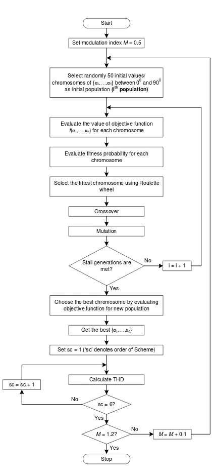
schemes as in Table 1 and at several values of modulation index M. Elimination of triple harmonics is not conducted in this study because they are automatically removed from line-to-line voltage for three-phase power system applications.The whole steps of the study are summarized by flowchart in Fig. 2.
Table 1. Variation of number of harmonic orders to be minimized
Scheme 1 Only 5th harmonic to be minimized
to be minimized (as appeared in (4))
5. RESULTS AND DISCUSSION
The
simulation
results
comprise
switching
angles
obtained
by
GA
optimization and the resulting THD along
with the FFT of the output voltage waveform.
Fig. 3 shows the THD versus modulation
index. As can be seen in Fig. 3, there is no
strict relationship between the obtained THD
and the number of minimized harmonic
orders. For example, at
M
= 0.7, the lowest
THD, i.e. 4.65%, is obtained with Scheme 3,
that is when only 5
th, 7
th, and 11
thharmonics
are minimized. On the other hand, Scheme 6,
which is the most complicated scheme, does
not give satisfying THD value of 5.36%.
Select randomly 50 initial values/ chromosomes of {α1,…,α5} between 0
0 and 900 as initial population (ith
population)
Start
Evaluate the value of objective function
f(α1,…,α5) for each chromosome
Evaluate fitness probability for each chromosome
Select the fittest chromosome using Roulette wheel
Crossover
Mutation
Stall generations are
met? i = i + 1
Choose the best chromosome by evaluating objective function for new population
Get the best {α1,…,α5}
Figure 2. Flowchart of the study
Jurnal Nasional Teknik Elektro
77
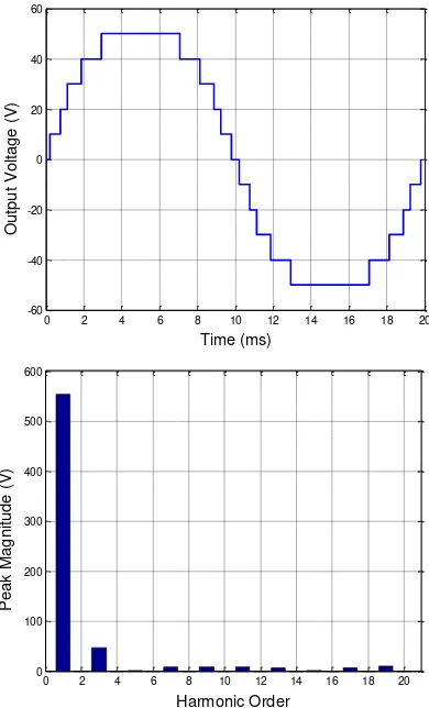
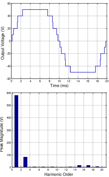
at M = 1.1 and M = 1.2. The lowest THD for bothM values are 3.03% and 2.76%, respectively. The values of switching angle for these cases are listed in Table 2, while Figs. 4 and 5 present their FFT representations, which are evaluated until 20th harmonic. As seen from FFT analysis in
Figs. 4(a) and 4(b), all odd harmonics up to 20th
order have been minimized, resulting in low THD.
Figure 3. THD versus M for various schemes Table 2. The values of switching angles for the
lowest THD
Simulations to minimize harmonics in 11-level multi11-level inverter have been conducted with several schemes. Each scheme represents different number of harmonics to be minimized. For each scheme, THD is evaluated until 20th
harmonics at various values of modulation index. All optimization processes are automated with MATLAB built-in GA toolbox, which requires only basic MATLAB programming. The following conclusions can be made.
1. The number of minimized harmonics does
7th harmonics, are minimized.
3. The lowest THD values are obtained, at several modulation index values, when all or most harmonics, i.e. 5th until 19th harmonics,
are minimized.
Figure 4. Output voltage waveform and corresponding FFT analysis
78
Jurnal Nasional Teknik Elektro
Figure 5. Output voltage waveform and corresponding FFT analysis
for Scheme 5 at M = 1.2 REFERENCES
[1] K. Kananda and R. Nazir, “Konsep
pengaturan aliran daya untuk PLTS tersambung ke sistem grid pada rumah
tinggal,” Jurnal Nasional Teknik Elektro,
vol. 2, no. 2, pp. 65-71, 2013.
[2] D. P. Sari and R. Nazir, “Optimalisasi
desain sistem pembangkit listrik tenaga hybrid diesel generator-photovoltaic array menggunakan HOMER (studi kasus: Desa Sirilogui, Kabupaten Kepulauan Mentawai),” Jurnal Nasional Teknik Elektro, vol. 4, no. 1, pp. 1-12, 2015. [3] L. M. Tolbert, F. Z. Peng, and T. G.
Habetler, “Multilevel converter for large
electric drives,” IEEE Transactions on
Industry Applications, vol. 35, no. 1, pp. 36-44, 1999.
[4] J. Rodriguez, J. Lai, and F. Z. Peng, “Multilevel inverters: A survey of topologies, controls and applications,” IEEE Transactions on Industrial
Electronics, vol. 49, no. 4, pp. 724-738, 2002.
[5] J. S. Lai and F. Z. Peng, “Multilevel
converters – A new breed of power
converters,” IEEE Transactions on
Industry Applications, vol. 32, no. 3, pp. 509-517, 1996.
[6] Z. Du, L. M. Tolbert, and J. N. Chiasson, “Active harmonic elimination for multilevel converters,” IEEE Transactions on Power Electronics, vol. 21, no. 2, 2006.
[7] IEEE Std 929-2000, “IEEE Recommended Practices for Utility Interface of Photovoltaic Systems”. [8] M. Manjrekar and G. Venkataramanan,
“Advanced topologies and modulation strategies for multilevel converters,” in Proc.IEEE Power Electronics Specialists Conference, Baveno, Italy, 1996, pp. 1013-1018.
[9] T. Bruckner and D. G. Holmes, “Optimal
pulse-width modulation for three-level
inverters,” IEEE Transactions on Power
Electronics, vol. 20, no. 1, pp. 82-89, 2005.
[10] P. N. Enjeti, P. D. Ziogas, and J. F. Lindsay, “Programmed PWM techniques to eliminate harmonics: A critical
evaluation,” IEEE Transactions on
Industry Applications, vol. 26, no. 2, pp. 302-316, Mar./Apr. 1990.
[11] A. M. Amjad and Z. Salam, “A review of soft computing methods for harmonics elimination PWM for inverters in renewable energy conversion systems,” Renewable and Sustainable Energy Reviews, vol. 33, pp. 141-153, Feb. 2014. [12] I. J. Ramerirez-Rosado and J. L. Bernal-Agustin, "Genetic algorithms applied to the design of large power distribution systems," IEEE Transactions on Power Systems, vol. 13, no. 2, pp. 696-703, 1998. [13] B. Ozpineci, L. M. Tolbert, and J. N. Chiasson, "Harmonic optimization of multilevel converters using genetic algorithms," IEEE Power Electronics Letters, vol. 3, no. 3, pp. 92-95, 2005. [14] D. Kumar, S. Pattnaik, and V. Singh,
“Genetic Algorithm Based Approach for Optimization of Conducting Angles in
Cascaded Multilevel Inverter,”
Jurnal Nasional Teknik Elektro
79
Research and Application, vol. 2, issue 3,pp. 2389-2395, 2012.
[15] M. T. Hagh, H. Taghizadeh, and K. Razi, "Harmonic minimization in multilevel inverters using modified species-based particle swarm optimization," IEEE Trans. Power. Electron., vol. 24, no. 10, pp. 2259-2267, 2009.
Author’s Biography