5-axis 3D Printer
Designing a 5-axis 3D printer
Øyvind Kallevik Grutle
Øyvind Kallevik Grutle
3D printers have in recent years become extremely popular. Even though 3D printing technology have existed since the late 1980’s, it is now considered one of the most significant technological breakthroughs of the twenty-first century. Several different 3D printing processes have been invented during the years. But it is the fused deposition modeling (FDM) which was one of the first invented that is considered the most popular today. Even though the FDM process is the most popular, it still suffers from some issues.
This thesis looks at the possibility of removing these issues by using a 5-axis system. To explore this, a 5-5-axis FDM printer called the Pentarod have been created by extending a 3-axis FDM printer with two extra axes. Then parts that can simulate the two main issues of a FDM printer have been printed with the Pentarod to see if it can elliminate the lacks of a 3-axis FDM printer.
I would like to thank my supervisor, Mats Høvin, for the continuous guidance and support throughout the thesis work.
II The Project 21
3 Building a 5-axis system 23
3.1 Planning the 5-axis system . . . 23
4 Programming a 5-axis system 47 4.1 Original system . . . 47
4.2 5-axis system . . . 47
4.3 Tool vector to angles . . . 48
4.4 Transformation . . . 49
4.5 Coding the 5-axis system . . . 51
7.1.1 The Pentarod . . . 79
7.1.2 System compatibility . . . 80
7.1.3 Test prints . . . 80
7.1.4 Advantages with a 5-axis FDM system . . . 80
7.2 Conclusion . . . 80
7.3 Future work . . . 81
1.1 Side view of a FDM print . . . 4
2.1 Illustration of the a FDM printer . . . 8
2.2 Configuration of Delta 3D printer and Cartesian 3D printer . . 9
2.3 Multi axis systems designations and directions . . . 10
2.4 Slicing a solid model . . . 11
2.5 Illustration of Cutter Location coordinates {X, Y, Z} and its tool vector {I, J, K} . . . 13
3.6 Illustration of how the relation between A-axis and Z’ distance are found . . . 29
3.7 The evolution of the platform . . . 31
3.8 Print plate attachment on the first version . . . 31
3.9 Motor and worm gear system on the C-axis mount, for the first version . . . 31
3.20 Motor and worm gear system on C-axis for the second version 38 3.21 Sliding motor mount on the second version . . . 39
3.24 The nozzle mount of the second version . . . 41
5.5 G-code simulation of surface smoothing test on xy-plane . . . 62
5.6 G-code simulation of support test . . . 62
5.7 G-code simulation of surface smoothing test on xz-plane . . . 63
5.8 Bad result of surface smoothing tests . . . 65
6.3 Magnified view comparison for XY-surface and part with 0.1 mm layer height . . . 74
6.4 Magnified view comparison for XY-surface and part with 0.1 mm layer height, top of parts . . . 75
6.5 Magnified view comparison for XY-surface and part with 0.2 mm layer height . . . 75
6.6 Magnified view comparison for XY-surface and part with 0.4 mm layer height . . . 75
6.7 Magnified view comparison for XZ-surface and part with 0.1 mm layer height . . . 76
6.8 Magnified view comparison for XZ-surface and part with 0.1 mm layer height, top of parts . . . 76
6.9 Magnified view comparison for XZ-surface and part with 0.2 mm layer height . . . 76
6.10 Magnified view comparison for XZ-surface and part with 0.4 mm layer height . . . 77
6.11 Comparison of the part with support structure and the same part printed on the 5-axis system . . . 78
3.1 Stepper motor specification . . . 25 3.2 Motor accuracy in the worst case of the first version . . . 27 3.3 Motor accuracy in the worst case for the second version . . . . 38 3.4 Results of A-axis stress test for the second version . . . 45 3.5 Results of C-axis stress test for the second version . . . 45
CNC Computer Numerical Control
CAD Computer-Aided Design
CAM Computer-Aided Manufacturing
FDM Fused Deposition Modeling
FFF Fused Filament Fabrication
SLA Stereolithography
SLS Selective Laser Sintering
LDM Laser Metal Deposition
PLA Polylactic acid
ABS Acrylonitrile Butadiene Styrene
DIY Do It Yourself
G-code A language for describing tool paths for CNC and 3D printers
CL Cutter Location
MCS Machine Coordinate System
ISO International Organization for Standardization.
ROBIN Robotics and Intelligent systems research group at the University
Introduction
1.1
Introduction
The earliest 3D printing technology surfaced already in the late 1980’s. However, until the late 2000’s 3D printing technology was still expensive and mostly used by industry. In 2004 Adrian Bowyer conceived the RepRap concept of an open source and self-replicating 3D printer. During the next years Bowyer and his team at the University of Bath developed working prototypes of 3D printers, based on this concept. In January 2009 the first commercially 3D printer was offered for sale, in kit form and based on the RepRap concept. This printer used the Fused Filament Fabrication (FFF) more commonly known as Fused Deposition Modeling (FDM). FDM printers builds structures layer by layer from the bottom-up, by heating and extruding material on a build plate.
This marked a turning point for the 3D printer technology, after which 3D printers became commercially available. From this point onwards 3D printing technology became extremely popular. Both cheap and do it yourself (DIY) printers have surfaced using different 3D printing technologies. Today the FDM printers are the most popular 3D printers. This is most likely because the FDM printers are consumer friendly, can create rigid parts, and are low cost [50].
1.2
Problems with FDM printers
FDM printers still have some weaknesses including accuracy and their inability to print overhanging structures without support [50].
The accuracy can be improved to some extent by lowering the layer height and using a nozzle with a smaller diameter. Even though the accuracy is improved by these methods, there will still be problems when printing surfaces that are not parallel with the print plate. An example of this can be seen in Figure 1.1.
1.3. POSSIBLE SOLUTIONS
Figure Printed layers
Figure 1.1: Side view of a FDM print
will approximately double. When using a nozzle with a smaller diameter the print time will also increase, because the volume of the plastic the printer can extrude will be dramatically reduced [58]. Time is also a problem when using support material to print structures with overhangs, as the support structure creates more work for the FDM printer.
1.3
Possible solutions
FDM printers build up parts with the additive manufacturing process, the opposite process is called subtractive manufacturing. A common technology that uses the subtractive manufacturing process are CNC mills. CNC mills are controlled in a similar manner as FDM printers, but remove material from a work piece instead of adding it.
For CNC mills the surface problem have been solved in three ways: different types of cutting tools, tool paths that are coordinating movements in three dimensions instead of only two and multi-axis mills. Tool paths movements in three dimensions would not solve the support structure issue of FDM printers, and different cutting tools are not an option in a FDM printer. In multi-axis mills, the surface problem has been solved by rotating the work piece or the tool, so that the tool can mill from different angles, and thereby create a smooth surface. The most common multi-axis configuration when working with different structures, is a 5-axis mills.
The weakness a FDM printers suffer today is that the printed parts are always printed bottom-up. By rotating either the nozzle or the printed part, as done in 5-axis mills, these problems could be eliminated. Therefore, this thesis will focus on the creation of a 5-axis FDM printer.
1.4
Goals of the thesis
Both of these faults can be addressed to some degree on a 3-axis FDM printer, but they are time consuming, and even when the accuracy is increased the final part still have flaws on surfaces not parallel with the print plate.
The objective of this thesis is to see if a 5-axis FDM printer can solve these issues. To test this theory, an already developed open source FDM printer will be extended with two rotary axes, to work as a 5-axis FDM printer. Then the two weaknesses, accuracy and ability to print overhanging structure without support, of a FDM printer will be tested to see if a 5-axis FDM printer can eliminate these without without severely extending the print time.
Since this system will be based on an open source printer, the 5-axis system will be released as an open source project when this thesis is finished.
1.5
Outline of the thesis
This thesis is divided into 3 parts; Introduction, The Project, and Conclu-sion and Results. The three parts are again branched into 7 chapters: In-troduction, Background, Building a 5-axis system, Programming a 5-axis system, Printing with a 5-axis system, Results and Analysis, and Discus-sion:
• The “Background” chapter explains the relevant information for this thesis, and then some of the previous work and research relevant for this project is provided. This chapter also lists the tools and programs used to realize this thesis.
• The “Building a 5-axis system” chapter explains the designing and building procedures for the system. This chapter is divided into four parts. The first part explains the choice of design and the requirements of the system. The second part point out the planning and building process of the first version. The third part discuss the results and problems with the first version. The last part explains the planning and building process of the second and final version.
• The “Programming a 5-axis system” chapter explains how the original firmware is working and how it is modified to work as a 5-axis system.
• The “Printing with a 5-axis system” chapter starts with explaining how the G-code for testing the system was created, then the printing process with the printer is explained.
• The “Result and analysis” chapter present and analyze the final version and its printing results.
Background
The background theory is presented in this chapter. Also, some discussion regarding central aspects of this thesis is made.
2.1
Computer Numerical Control (CNC)
When movement and tool handling is controlled by a computer it is typically a computer numerically control system (CNC). A CNC system is normally built up with 3-axis, X and Y for movement of the work piece and Z for movement of the tool. With a CNC system it is possible to get a high precision along the axis, with the help of stepper motors or servo motors. These motors are usually geared down to get an even better precision. In a typical CNC system the operator creates a series of steps from a computer aided design (CAD) and the machine converts these steps into movements to create a part that closely matches the original CAD.
2.2
Additive Manufacturing
Additive manufacturing is a process where digital 3D design data is used to build up a 3D structure layer by layer, by depositing material. The material used by additive manufacturing can be plastic, liquid, powder filaments or even paper [4, 57]. The chosen material is dependent on which additive manufacturing method that is being used. Some of the different additive manufacturing methods that exists today are:
•Stereolithography (SLA)
2.2. ADDITIVE MANUFACTURING
•Fused deposition modeling (FDM)
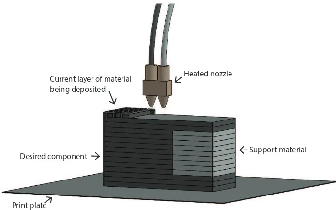
FDM was developed and implemented the first time by Scott Crump in 1980s and was commercialized in 1990 by Stratasys. Other 3D companies have adopted similar technologies but under other names, such as Fused Filament Fabrication (FFF). FDM printers builds structures layer by layer from the bottom-up by heating and extruding thermoplastic filament such as Acrylonitrile Butadiene Styrene (ABS) and Polylactic acid (PLA). The extruder travels between points in the X, Y and Z coordinates. These points are found by slicing a CAD model into layers defined by the layer height, and computing traveling paths. To support overhanging layers, support material is often used in FDM printer. The support material can be dissolved after a print is complete [34, 57]. An illustration of a FDM printer can be seen in Figure 2.1.
•Selective Laser Sintering (SLS)
SLS was developed by Carl Deckard, a student of Texas University, and his professor Joe Beaman in 1980s. The SLS technology is in some ways quite similar to SLA. The main difference between the two is that SLS uses powdered material instead of liquid. Unlike the methods described above, SLS systems do not need support structure since the object being printed is constantly surrounded by unsintered powder [57].
Heated nozzle
Support material Desired component
Print plate
Current layer of material being deposited
2.2.1 FDM printers
As mentioned in section 1.1 FDM printers are the most popular 3D printers today. Because of their popularity, simplicity and availability in the open source community a FDM printer was chosen for for this thesis. FDM printers exists in multiple different configurations, the two most common types being:
•Cartesian
The Cartesian 3D printers consist of three rails that have movement along the axes of the Cartesian plane. Controlling the movement of a Cartesian 3D printer is fairly simple mechanically and software wise as there is only linear movement along the axis. Most of the 3D printers on the market today use the Cartesian system [10]. An illustration of the configuration and movement of a Cartesian 3D printer can be seen in Figure 2.2b.
•Delta
The Delta 3D printers consists normally of three vertically rails that are standing upright in a triangular configuration. The extruder is connected to these rails with three arms, and its movement is achieved by moving them up and down. Due to this, it is more mathematically complex to find the head position of a Delta printer, which makes the Delta printers more advanced software wise. Delta printers are becoming more popular in both industry and the 3D printing consumer community. This is because the Delta printers configuration enables faster printing and a more compact size than the Cartesian printers [10]. An illustration of the configuration and movement of a Delta 3D printer can be seen in Figure 2.2a.
(a) Delta 3D printer. Printer head can move in any direc-tion quickly
(b) Cartesian 3D printer. Each element moves only in one direction.
Figure 2.2: Illustration of Delta 3D printer (a) and Cartesian 3D printer (b) [26].
2.3. SUBTRACTIVE MANUFACTURING
2.3
Subtractive Manufacturing
Subtractive manufacturing is a collection of various controlled processes where a piece of raw material is being removed to create a desired final shape. Some of these processes are drilling, turning, milling, grinding and chip formation. In the recent years it has become more common to entrust the control of the process to CNC systems. [2, 31].
The CNC milling machine typically operates the same way as a Cartesian 3D printer, but it removes material instead of adding it. Because of this similarity between 3D printers and CNC milling machines, and the fact that multi-axis CNC mills already have existed a while. Multi-axis CNC mill have been the main inspiration for the 5-axis 3D printer.
2.3.1 Multi-axis CNC mill
When a CNC system has more than 3-axis it is called a multi-axis system. Now the computer also controls rotation (ABC) and parallel movement (UVW) along X, Y or Z, as shown in Figure 2.3. (ABC) specifies a rotation around an axis, and (UVW) specifies a parallel movement along the axes. For example, it is possible to move the work piece along the X-axis in addition to moving the tool along the X-axis.
Figure 2.3: Multi axis systems designations and directions [6].
The 5-axis CNC machine is one of the most used multi axis systems for creating different parts when high precision is needed [62]. The two extra axes in a 5-axis system tend to be rotation axes. These rotations can either be done by rotating the head, where the tool is attached, or rotating the table, where the work piece is attached. Therefore, the 5-axis system can have three different configurations:
•Table/Table
•Head/Head
In a Head/Head machine all the rotary motions are executed by the spindle head of the machine. These machines can be both vertical and horizontal. When both of the rotary axes are in the head it is possible to change the whole head. This makes it possible to achieve different behaviors based on the configuration of the head [6].
•Head/Table
Head/Table machines are a combination of the two previous config-urations. Head/Table machines have one rotary axis where the tool is attached, and one at the table of the machine. For milling Head/T-able machines are arguably the most capHead/T-able of these three groups, and they can machine large, heavy parts [6].
2.4
Tool path generation
To be able to create a structure with a milling machine or 3D printer, the tool path from a 3D model has to be generated. This is done by slicing the triangular polygon, from a geometry file, into horizontal layers [34]. The more layers the structure is sliced into the more accurate the geometry approximation will be. However the printing or machining process of the structure will take a longer time. Each polygon is converted to a contour line between the polygons and the slicing plane to find the outline of the model. The process from the solid model to a sliced model can be seen in Figure 2.4. When all the contour lines are found, they are sorted and the interior/exterior area of each contour is found. Tool paths filling in the interior for 3D printing or exterior for CNC machining, are then generated and written to a file as for example standard G-code [34].
2.5. G-CODE
2.5
G-code
G-code was originally defined by the Electronics Industry Association (EIA) in the 1960’s [25]. G-code is the common name for the most widely used numerical control programing language [31]. The G-code specifies what a machine should do using instruction lines. It can be used to change the settings of the machine, put it in special modes or tell it where it should move its tool. The simplest form of G-code can be used to specify linear interpolation. This is done by sending the G-code commandG01/G1with X, Y, Z, F, where X, Y and Z is the position the tool should move to in the Cartesian coordinate system, given as mm or inch. The feedrate (F) defines the movement speed of the tool tip, normally interpreted as mm/min or inch/min. To keep the file size of the G-code to a minimum, the G-code is modal. This way if the G-code does not get a new value for an axis, is kept in the old position [34].
2.5.1 5-axis G-code
5-axis G-code has all the functionality as the ordinary G-code, but additionally commands the rotation of the two extra axes. The most common way to command the rotation is by adding A, B and C to the G-code. A, B and C define the rotation angles, an illustration of this can be seen in Figure 2.3. When A, B and C are used to represent the rotation in a system, the G-code will be dependent on the machine configuration the G-code is created for. To avoid this issue it is possible to represent the rotation by using Cutter Location (CL) points represented in ISO format as {X, Y, Z, I, J, K}, where {X, Y, Z} are the coordinates of CL and {I, J, K} are the tool vector values [15, 43]. When representing the rotation as {I, J, K} the machine can compute which axes it should move to get to that position, based on its configuration. An illustration of the tool vector, and its values in a Cartesian coordinate system, can be seen in Figure 2.5.
Tool vectors are also a great way to simplify post processor creation. When a 5-axis tool path is programed using a CAM system, the software already computes the commanded moves with tool vectors. Therefore, by using tool vectors in the machine, the post processor can simply output these created moves without having to translate them. When using {A, B, C} representation the post processor have to translate every move into an A-, B- or C-axis [15].
Tool v ector {I, J
, K}
Cutter location coordinates {X, Y, Z}
Tool v ector {I, J
, K}
Z
Y
X J
K
I
Figure 2.5: Illustration of Cutter Location coordinates {X, Y, Z} and its tool vector with the values {I, J, K}
2.6
Backlash
Backlash is the maximum distance or angle two parts in a mechanical system can move without applying a force or motion to the next part in the mechanical sequence [8]. In gears this distance is measured as the clearance between two mated gear teeth. This clearance is necessary to avoid e.g. interference, wear, and excessive heat generation. It also ensures proper lubrication and compensates for manufacturing tolerances. [29, 33]. In Figure 2.6 the concept of backlash is illustrated.
Figure 2.6: Illustration of backlash [11]
2.7. OPEN SOURCE
2.7
Open source
Open source is a develop model where the developer distributes their code and machine plans freely. End users are encouraged to modify both the plans and the code, and then share their modifications. This way the creators can get new ideas and inspiration on how they can improve their machines. In the open source community the profit of a product is not the core incentive, but instead they are driven by curiosity and the desire of solving new problems [40, 41].
The plan with this thesis is for it to be open source, and it will be published on a suitable site online when the master’s thesis is completed.
2.8
The RepRap project
The RepRap project started with an idea Adrian Bowyer published in February 2004. The idea was to make an affordable 3D printer which could print out most of its own parts, and could be assembled with parts that were cheap and easy to get. RepRap follows the principles of the Free Software Movement, and therefore distributes all the RepRap machines as open source [3]. The first four official 3D printing machines made by the RepRap project where released in March 2007 named “Darwin”. After this, both the RepRap core team and the community have made multiple 3D printer models and variations of these.
2.9
Previous work
When work on this thesis began there was only one other system that where capable of 5-axis 3D printing, but during the time spent on this work more 5-axis 3D printers have surfaced. Some of these are:
•DMG Mori:
January 10, 2014 DMG Mori released a video1 of a hybrid machine capable of both subtractive and additive manufacturing of metal. This machine has a table/table configuration and is able to change its tool depending on which kind of machining it is doing. Other than an article posted 24. October 20142the information about this machine
has been sparse.
•TWI:
Om November 14, 2014 TWI released a video3 of a 5-axis Laser metal deposition (LDM) printer for metal. This printer also uses the table/table configuration and uses LDM technology, developed by TWI, to print the metal. The information about this printer has been sparse except for the general information TWI has released.
1DMG Mori 5-axis hybrid:https://www.youtube.com/watch?v=s9IdZ2pI5dA
2Article DMG Mori: http://www.engineering.com/AdvancedManufacturing/ArticleID/
8778/3D-Printing-and-5-Axis-Machining-Combined-in-One-Machine.aspx
•5axismaker:
September 22, 2014 5axismaker created a Kickstarter for a 5-axis multi-fabricator. The idea behind this machine is to create a 5-axis system in which it is possible to change tools on. The set of tools would be a CNC mill, touch-probe, 3D printer, wire-cutter and others [1, 39]. When this machine was put on Kickstarter, the 3D printer head was still in development. On June 10, 2015 they released a video4 of the 3D printer capability of their machine. This machine has a head/head configuration.
5-axis 3D printers do exist today, but either the information about them is difficult to find or they are still in development. Because of this the main inspiration of this thesis comes from 5-axis CNC milling machines, since it is a more developed field and it is better documented. Although the 5-axis CNC field is more developed and better documented, were no public available information about how the rotary system of 5-axis CNC machine are built found during the research of this thesis. Therefore will the 5-axis rotary system in this thesis be build from scratch.
2.10
Tools and programs used
This section describes tools and programs used in this thesis.
2.10.1 Duet
The Duet was developed by Andy Hingston and Tony Lock from Think3dPrint3d in conjunction with RepRapPro. The Duet combines the Arduino Due micro controller with four stepper motor controllers, Ether-net, HI-Speed SD card slot and more [12, 42].
The Duet is the 3D Printer controller board used in this thesis.
Duex4
The Duex4 is an expansion card for the Duet. It has four extra stepper drivers, another I2C digipot, 4 FETs and corresponding thermistor inputs [42]. The Duex4 was developed to make it easy to add multiple extruders to a 3D printer. The Duet and Duex4 can be seen in Figure 2.7.
2.10. TOOLS AND PROGRAMS USED
Figure 2.7: The Duet at the bottom and the Duex4 at the top [42]
2.10.2 Stepper motors
Stepper motors are used in this thesis to control all the axes and the extruder.
A stepper motor is driven by a magnetic gear with multiple teeth that are connected to the rotor in the motor. In the stator there are electro magnets which are equipped with corresponding teeth, and the rotor rotates when these electro magnets are turned on and off in a specified sequence. Since the magnetic force is heavily dependent on the air gap between the magnets, a small step size can be achieved. Normally a stepper motor has a step size between 200-400 steps each revolution [32]. A stepper motor has three ways to get input for the movement; full step, half step and micro step. When using full step, the drives always have two phases on. In half step the drives alternates between two phases on and single phase on. Half step has a double resolution over full step, but the average torque is lower. To get micro step the driver sends an AC waveform to the motor, which usually is sinusoidal. This way the phases pulls and pushes on the teeth of the iron gear with different strengths, and thereby we get multiple steps where full step only gives us one [32].
2.10.3 Worm drive
Worm drive was used in this thesis to gear down and transfer the movement of the rotary axes.
A worm drive is a gear arrangement, which consists of a worm and a worm gear. The worm has the form of screw, while the worm gear has a shape that are similar to a spur gear. A Worm drive offers a high gear reduction, but still has a small size [49, 63]. As seen in Figure 2.9 the worm, and the worm gear has its drive axes at 90° to each other.
Figure 2.9: Example of a worm drive [49]
2.10.4 Fortus 250mc
In this thesis, the Fortus 250mc 3D printer is used to print most of the parts of the 5-axis system.
Fortus 250mc is manufactured by Stratasys and utilizes the Stratasys patented Fused Deposition Modeling (FDM) technology. Fortus 250mc uses ABSplus-P430 as filament, has a build envelope of 254 mm * 254 mm (base) * 305 mm (height), and can print with a layer height of 0.178 mm, 0.254 mm or 0.330 mm. To avoid wrapping of the ABS plastic the Fortus 250mc uses a heated camber that creates a thermally isotropic build envelope. The Fortus 250mc allows for a certain degree of overhang, but needs to use support structure when the overhang is over 30° - 45°. The support structure can then be removed by breaking it, or by dissolving it in a chemical bath with high pH value (basic). Removing the support in a chemical bath usually takes some time, but it can remove support structures that are hard to reach [27, 28]. For generating tool paths for the Fortus 250mc the program Insight is being used. Insight prepares a STL file for 3D printing by optimizing build orientation, slicing, creating support structure and generating the tool path [38].
2.10.5 Objet Connex 500
In this thesis the Objet Connex 500 3D printer is used to print parts where a high accuracy was needed.
2.10. TOOLS AND PROGRAMS USED
which is instantly cured with the use of UV lamps. This is done for each layer until the model is finished [44, 45]. The Objet Connex 500 can print with multiple materials on the same print, and can mix these material to create materials with different properties. The printer has a build resolution of 600 dpi for the X-axis, 600 dpi for the Y-axis and 1600 dpi for the Z-axis. The printer can print with a layer height down to 16 micrometer [44, 46].
2.10.6 Epilog Zing 24 Laser 30W
The Epilog Zing 24 Laser used for this thesis have a laser wattage of 30W. Epilog Zing 24 Laser is manufactured by Epilog Laser. It is one of their Zing Laser Series. The Epilog Zing 24 has a work area of 610 mm * 305 mm and can cut in multiple materials as long the material does not create poisonous gases when heated up.
2.10.7 SolidWorks
In this thesis, SolidWorks have been used to design and test the different versions of the 5-axis 3D printer. There exists multiple CAD software producers [13], but SolidWorks was chosen because the University of Oslo has licenses for it.
SolidWorks is perhaps the most popular CAD software available today. When building a model in SolidWork the designer starts with sketching a 2D model, which is extruded into a 3D model [52].
2.10.8 HSMWorks
HSMWorks is a CAM extension for SolidWorks. HSMWorks is made to create a seamless workflow between a CAD and CAM software. HSMWorks has the ability to create tool path strategies for 2D, 3D and multi-axis milling. HSMWorks also includes machine simulation, which can simulate tool paths on a machine assembled in SolidWorks and a backplot tool which can simulate G-code [35].
HSMWorks was used in this thesis to generate multi-axis tool paths, simulate these tool paths on the 5-axis 3D printer with the machine simulation and simulate manually generated 5-axis G-code with the backplot function.
2.10.9 Printrun
Printrun was used in this thesis to control the 5-axis 3D printer and send G-code to it, with pronterface.
2.10.10 G-code generators
A G-code generator is a program that is cutting a 3D model into a number of slices of a given height, and describing each slice as the path the printer head should follow. This path is described as multiple points in a coordinate system, where each point is a G-code command. In this thesis two G-code generators where used:
•Cura
Cura is a free open source software developed by David Braam. Cura has a graphical user interface which is easy to use, has the option to add add-ons, and it is possible to adjust the settings of the slicer multiple ways [20].
•Slic3r
Slic3r is a free open source software that was born within the RepRap community in 2011. Slic3r was created to provide the 3D printing technology with an open and flexible tool chain. Slic3r has features as multiple extruders, brim, micro layering, bridge detection, command line slicing, variable layer heights, sequential printing (one object at time), honeycomb infill, mesh cutting, object splitting into parts, AMF support, avoid crossing perimeters, distinct extrusion widths, and much more [51].
Slic3r and Cura were used in this thesis to create G-code for the base and top structure of the 5-axis test parts.
2.10.11 C++
C++ is the main used programming language used for the Ormerod firmware, therefore the control of the 5-axis system is written in C++.
C++ is a general-purpose programming language with imperative, object-oriented and generic programing features. It also provides possib-ilities for low-level memory manipulation. C++ was developed as “C with classes” in 1979 by Bjarne Stroustrup. Later in 1983, it was renamed to C++. In 1988 C++ was standardized by International Organization for Standard-ization (ISO) [55].
2.10.12 Java
Java where used in this thesis to manually generate 5-axis G-code, Java where chosen because of its familiarity.
Building a 5-axis system
When building the 5-axis system, two versions were created. This chapter will explain the planning, building, and testing process of both of these versions. The problems with the first version and the reason to create a second version will also be explained in this chapter.
3.1
Planning the 5-axis system
3.1.1 Choosing a base system
When looking for a 3-axis 3D printer that could be expanded to work as a 5-axis system, the 3D printers from the RepRap community was an obvious choice. Since they are designed to be easy to build and modify. The RepRap community has multiple 3D printers that would be suitable for this project. In the beginning of this thesis ROBIN’s main supplier of components (RS-components), started to sell the RepRapPro Ormerod. Therefore the Ormerod was chosen for this project. This printer is also a good choice since it is easy to expand upon without to many significant changes to the design.
3.1. PLANNING THE 5-AXIS SYSTEM
3.1.2 Choosing 5-axis configuration
Working 5-axis mills already exist. These have been the main inspiration for this 5-axis printing system. 5-axis systems consists of three main configurations which are; table/table, head/head and table/head, as were explained in section 2.3.1. In this project it was decided to use a table/table configuration, the main reasons for this are:
• Two extra axes would have extra weight. Because of this extra motors have to be added. In a head/head or head/table system these motors have to be added to the X- and Z-axis of the Ormerod. This could prove more difficult than adding extra motors on the Y-axis, which a table/table system needs.
• A head/head system or a head/table system needs to be compact at the head to work properly. This will make the system harder to assemble and redesign. Whereas a table/table system can easily be built larger as long the weight is compensated with more and/or stronger motors.
• As mentioned in section 2.3.1, one of the benefits of a head/head or head/table system over a table/table system, is that it can work with heavier work pieces. This system will print with plastic, and therefore the weight will not be an issue.
• One of the problems a table/table have is the attachment of the work piece. This could be an issue with printing on a table/table system, since adding attachment to a part which is being printed could be difficult. After testing a few prints on the Ormerod, this was found not to be an issue. Since the plastic sticks quite well on the print plate, and force must to be applied to remove it.
• Another problem that might come with a head/head and head/table configuration is that the plastic might not connect completely or start floating down the structure when printing 90° on an existing structure. While there are no research that can support this claim, a table/table system is preferable to be sure this will not be an issue.
3.1.3 Finding the origin in the system
Figure 3.2: Intersection point of the rotary axes for a table/table configura-tion[14]
3.1.4 Choosing stepper motors
The motors that were included in the Ormerod kit are the JK42HS34-1334A shown in Section 3.1.4. For the 5-axis system three more motors were needed: one extra for the Y-axis because of added weight, one for the A-axis and one for the C-axis. Because of availability, the SM-42BYG011-25 shown in Section 3.1.4 were chosen as the extra motors. As seen in Section 3.1.4, these two motors are similar in most cases, and therefore they can be added to the system without any modifications.
Model No. JK42HS34-1334A SM-42BYG011-25 42BYGHM809
Step Angle 1.8° 1.8° 0.9°
Step angle accuracy ±5% ±5% ±5%
Step per revolution 200 200 400
Current/Phase 1.33A 0.33A 1.7A
Holding Torque 2.2 kg*cm 2.3 kg*cm 4.9 kg*cm
Detent Torque 120 g*cm 163 g*cm 224 g*cm
Size (WxLxH) 42x42x34 mm 42x42x34 mm 42x42x48 mm
Table 3.1: Stepper motor specification [21, 22, 37]
3.1.5 Controlling the stepper motors
3.1. PLANNING THE 5-AXIS SYSTEM
RepRap community has also built an expansion board for the Duet called Duex4. The expansion board is built to create the possibility to add four more extruders to the 3D printer. Since the Duex4 uses the same stepper drivers as the Duet it is possible to use these four extra stepper drivers for the extra axes, as shown in Figure 3.3.
Figure 3.3: Wiring for Duet and Duex4. Figure based on Duet illustration [12]
3.1.6 Accuracy for the rotary system
without micro steps is 1.8°, with 1/16 micro step, the step angle for each step is 0.1125°. The arc length can be found using eq. (3.1) [9], wheresis the arc length,ris the radius of the circle andθis the angle in degrees.
s=π ∗r∗θ
180 (3.1)
The arc length movement for each micro step is found to be 0.13745 mm, which is 12 times higher compared to the accuracy of the X- and Y-axes, as seen in Section 3.1.6. To achieve the same accuracy a gear with ratio 1/12 and higher is needed. When working with a gear ratio this high and with the need of a compact solution for the C-axis, a worm gear system is the best choice. This due to the system’s compactness and high gear ratio, as mentioned in section 2.10.3. To make sure the A- and C- axes have a higher accuracy than the X- and Y-axes, a worm gear system with a 1/15 ratio is being used for this system. The accuracy obtained with this is shown in Section 3.1.6.
Table 3.2: Motor accuracy in the worst case of the first version
3.2
Planning the first version
When the Ormerod was assembled and tested, it appeared there were a few modifications that needed to be done on the original design to make it support a table/table configuration. The table/table configuration would add a rotary system on top of the Y-axis. This gives the Y-axis motor more weight to move compared to the original print plate on the Ormerod. To compensate this an extra motor had to be added to the Y-axis to make sure the Y-axis would be able to move the rotary system. The rotary system would also raise the print plate and be wider than the original print bed. To compensate these changes the platform and the Z-axis had to be expanded. As mentioned in section 3.1.3 it is convenient to keep the origin of the machine coordinate system (MCS) at the point where the rotary axes intersect. To make sure this is the case the design of the rotary system should be designed with the print plate in focus. The print plate should also have an adjustment ability to make sure the print plate is laying directly in this origin.
3.2. PLANNING THE FIRST VERSION
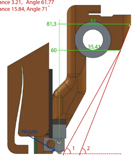
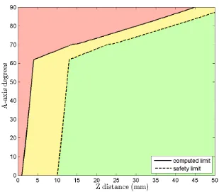
When the A-axis is rotated to an angle, the nozzle must to be able to reach the print plate. In the design of the Ormerod the nozzle mounting has obstructions on both sides, as can be seen in Figure 3.4. One of these sides is the cooling system for the nozzle and needs to be there, while the other side can be improved upon. To avoid that the system has different relations between the print plate and the nozzle is depending on the A-axis being negative or positive, whereas the A-axis will be limited to 0° - 90°. By doing this the gear system in the A-axis will also be preloaded by the weight of the C-axis mount. This will, as mentioned in section 2.6, eliminate problems with backlash in the A-axis. The relation between the A-axis angle and the Z’ distance between the nozzle and the print plate (for the original nozzle mounting) can be seen in Figure 3.5. The values in this graph has been computed by measuring the distances in SolidWorks and then computing the A-axis angle and Z’ distance. An illustration of how these values where found can be seen in Figure 3.6.
Figure 3.5: A-axis and Z’ limits for Ormerod. Computed limit is found as mentioned in section 3.2 and safety limit is the computed limit plus 10 mm. Values in red area will make the nozzle mount crash with the print plate, values in yellow area can make nozzle mount crash with the print plate mounts and for values in the green are the nozzle mount can move freely.
Z’
Nozzle
A
Obstruction
3.3. MODELING THE FIRST VERSION
3.3
Modeling the first version
3.3.1 The platform
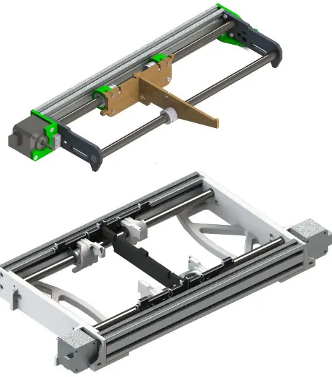
When redesigning the platform, a number of methods to create the mounting between the rotary system and the platform were considered. The original system uses laser cut plywood, and the same would have been preferable on this system. But since ROBIN did not have access to a laser cutter when the first version was created and milling the material would both be expensive and time consuming. The parts where therefore designed to be printable with the Fortus 250mc. As mentioned in section 3.2 an extra motor has to be added to the platform. To have the same motors on the Y-axis, the original motor was removed and two motors of the type SM-42BYG011-25 were added. The motor specification for this motor can be seen in Section 3.1.4. As seen in Figure 3.3 these motors are connected to separate drivers. This was done because there were unused drivers on the system, and to avoid problems with parallel and serial connection of motors [54]. The design of the new platform was inspired by the old design. The parts of the original design were mirrored and then welded together with a distance between them. To make sure the platform was rigid, a support structure was created in the bottom of the platform to stabilize the aluminium profiles. The result of the new platform compared to the Ormerod platform can be seen in Figure 3.7.
3.3.2 The rotary system
Figure 3.7: The evolution of the platform. The top picture are the platform of the original version (Ormerod), and the bottom are the platform of the first version
Figure 3.8: Print plate attachment on the first version.
3.3. MODELING THE FIRST VERSION
Figure 3.10: Motor axle bearing.
Figure 3.11: Axle to rotary system link, for the first version.
3.3.3 Lowering the nozzle
As mentioned in section 3.2, the nozzle mount on the original system gave the system severe limits regarding the relation between the A-axis angle and the Z’ distance between the nozzle and the print plate. To compensate for this, the mount for the nozzle was lowered by 50 mm, as seen in Figure 3.13. By doing this, the system has the possibility to reach a higher A-axis angle with a smaller Z’ value, as seen in Figure 3.14. The new nozzle mount as illustrated is much bigger than the previous versions, and because of this the X-axis had to be extended so the X-axis sensor would still work, the result of this can be seen in Figure 3.15.
Figure 3.13: First version nozzle mount, all distances are in mm.
3.3.4 The Z-axis
3.3. MODELING THE FIRST VERSION
Figure 3.14: A-axis and Z’ limits for First version. Computed limit is found as mentioned in section 3.2 and safety limit is the computed limit plus 10 mm. Values in red area will make the nozzle mount crash with the print plate, values in yellow area can make nozzle mount crash with the print plate mounts and for values in the green are the nozzle mount can move freely.
Figure 3.16: Top mount for Z-axis.
3.4
Modeling result of the first version
The first modeling process resulted in the first version, as seen in Figure 3.17. When assembling the first version, some problems with the initial design were noticed. One of the major problems was that the screw positions for the motors on A- and C-axis were difficult to reach. Because of this, it was difficult to adjust the distance between the worm and the worm gear. When the distance between the worm and the worm gear could not be adjusted properly, the worm gear system did not function accurately, and the A- and C-axis ended up with a backlash of 15° - 26°. The backlash was not a problem for the A-axis since it was limited to 0° - 90°, and therefore preloaded by the weight of the C-axis mount. However, for the C-axis this would be a severe problem when the rotation changes direction. To compensate this, the C-axis were preloaded to make sure the backlash was minimized. When the system was preloaded other problems surfaced, due to the added weight from the preload, the Y-axis was missing steps when moving. To compensate this the speed of the Y-axis was reduced until the Y-axis was able to move without losing steps.
3.5. TESTING THE FIRST VERSION
3.5
Testing the first version
From the beginning, it was clear that the system had some errors. To figure out the reason for this, both the axes were run 0° to 90° with steps of 1° three times each. A digital inclinometer was used as a method to efficiently find which precise angle the axes approached. The digital inclinometer works as a leveler, but allows for the exact measurement of an angle. The digital inclinometer used in these tests have an accuracy of ±0.2° [36]. Results from these tests can be seen in Figure 3.18 and Figure 3.19. These graphs shows the median of errors from the tests and range of the samples. Both the plots show the error of the axis along the X-axis and the degrees and revolutions of the worm along the Y-axis.
As seen in the plots, the error of the first version are quite severe. When considering the plot and the revolutions of the motor, it is obvious that the error is periodic. The error comes from the way the worm was connected to the stepper motor. The lining between the stepper motor and the worm was not working as it should, and therefore the worm had an elliptic movement. This elliptic movement made the teeth of the worm and the teeth of the worm gear to have different distances, depending on where the motor was in a revolution. The worm would then have a changing effect on the worm gear.
0 10 20 30 40 50 60 70 80 90
Figure 3.19: Angular error C-axis, first version
3.6
Problems with the first version
After working with the first version for a while, more problems appeared. The plastic around the screws on the platform cracked because the plastic was too thin. The links that connected the axle of the worm gear to the A-and C-axes were too thin A-and cracked which resulted in more backlash for the A- and C-axes.
Because of the problems that have been described, specifically the movement problems of A- and C-axis, the first version was not able to print properly with the 5-axis system. Therefore it was decided to modulate a new version where these problems were accounted for.
3.7
Planning the second version
3.8. MODELING THE SECOND VERSION
even more, and remove as much of the structure as possible on one side of the nozzle.
While planning the new rotary system it was apparent that the new design would increase in size and thereby mass. To make sure both the A-axis and the Y-A-axis would be able to move the new system, new and stronger motors were ordered. The specification of the new motors, 42BYGHM809, can be seen in Section 3.1.4. The new motors have doubled accuracy, 400 steps each revolution compared to 200 steps each revolution, and a holding torque that are more than double the original motors. Because of the doubled accuracy, the new system has an improved worst-case accuracy for the Y- and A-axis, as seen in Section 3.7.
Axis st epmm st epmm
Table 3.3: Motor accuracy in the worst case for the second version
3.8
Modeling the second version
3.8.1 The motor mount
To have a system that can adjust the distance between the worm and worm gear, the motor mount on the second version was connected with a sliding mount. This can be adjusted with the help of two screws and two springs between the A- or C- axis mount and the motor mount, as seen in Figure 3.21. Thus it is possible to adjust the distance between the worm and the worm gear. To deal with the size difference between the hole of the worm and the motor axle, the worm are attached to a 6 mm rod, which then were connected to the motor as seen in Figure 3.20. This way, the worm will not be able to move in an elliptic trajectory, and therefore the movement problems from the first version were eliminated. The motor mount was modulated so that the same part could be used for the A- and C-axis.
Figure 3.21: Sliding motor mount on the second version
3.8.2 The rotary system
Because of the new motor mount, both the A-axis mount and the C-axis mount had to increase in size. To simplify the modeling process, the C-axis mount were designed first. When the design of the C-C-axis mount were finished, the A-axis mount was quite straightforward. The result of the rotary system can be seen in Figure 3.22. In the first version, the links that connected the axle of the worm gear to the A- and C- axis broke. In order to compensate for this, the rod was extended to go through the bearing and fastened to the rotating parts. By doing this, it was easier to create a more durable fastening system. Due to this the print plate mount had to be expanded. While redesigning this a more accurate system for calibrating the print plate also were added. This calibrating system uses three springs, which are between the print plate mount and the holders of the print plate.
3.8. MODELING THE SECOND VERSION
3.8.3 The platform
As mentioned in section 3.7 one of the problems in the first version were that the frame around the screws on the platform were breaking. To avoid this problem the thickness of the platform had to be expanded. The new motors that are driving the Y-axis, are larger than the original motors, as can be seen in Section 3.1.4. Due to this the motor mount on the platform had to be remade to accommodate this.
During the modeling of the platform, the ROBIN group got access to a laser cutter, which allowed a more rigid redesign of the mounting between the rotary system and the platform. The new platform with the acrylic parts can be seen in Figure 3.23.
Figure 3.23: The platform of the second version
3.8.4 Lowering the nozzle even more
Figure 3.24: The nozzle mount of the second version nozzle, all distances are in mm.
3.8. MODELING THE SECOND VERSION
3.9
Modeling result of the second version
The result of the second version, called Pentarod, can be seen in Fig-ure 3.27. When assembling the second version, a problem with the slid-ing system for the motor holder appeared. While calibratslid-ing the distance between the worm and the worm gear, it still was difficult to find a perfect distance between the worm and the worm gear. To close together the mo-tors would not be able t rotate the gears. To far apart, the system would have too much backlash. However, with enough calibration the backlash in the A- and C-axis was reduced to 1° - 2°.
3.10. TESTING THE SECOND VERSION
3.10
Testing the second version
The second version was tested the same way as the first version, both the axis was moved from 0° to 90° with 1° step three times. The result of this can be seen in Figure 3.28 and Figure 3.29, which shows the median of the errors from the tests and the range of the samples. These plots shows that the new system has an improved accuracy for the A and C axis movement. There are still an angular error of -0.15° to 0.15° in the system, and since these values are well within the accuracy of the digital inclinometer,±0.2°, as mentioned in section 3.5, this was considered acceptable.
0 10 20 30 40 50 60 70 80 90
Figure 3.28: Angular error A-axis of the second version.
0 10 20 30 40 50 60 70 80 90
Figure 3.29: Angular error C-axis of the second version.
Error after run
Table 3.4: Results of A-axis stress test for the second version
Error after run
0° 90° 180° 360°
1. run -0.05° 90° 180.1° 360° 2. run 0° 90.05° 179.95° 359.9° 3. run 0° 89.95° 180° 359.95° 4. run 0.05° 90° 180.05° 360.05°
3.10. TESTING THE SECOND VERSION
1 G1 A0 2 G1 A45 3 G1 A90 4 G1 A45 5 G1 A90 6 G1 A45 7 G1 A0 8 G1 A45 9 G1 A0 10 G1 A90
G-code 3.1: Stress test A-axis.
1 G1 C0 2 G1 C180 3 G1 C360 4 G1 C180 5 G1 C360 6 G1 C180 7 G1 C0 8 G1 C180 9 G1 C0 10 G1 C360
Programming a 5-axis
system
This chapter presents how the original firmware is working and how it is modified to work as a 5-axis system.
4.1
Original system
It was decided in the early stages of the project to use an already working firmware for the 3-axis 3D printer instead of creating a new system for 3D printing. Hence it was possible to concentrate on the additional two axes. At the beginning of this thesis, there were three main versions of the Ormerod firmware: the original, ZPL’s version and DC42’s version. The three versions of this firmware could easily been used for this project, but the DC42 version had the best reviews by the community and therefore this version was chosen.
4.2
5-axis system
4.3. TOOL VECTOR TO ANGLES
To be able to implement this system, the original code, which has three drivers for the axes and five axes for the extruder’s, had to be rewritten to have five drivers for the axes, X, Y0, Y1, Z, A and C. This was done by changing a few parameters in the original code. The steps per unit that were used are shown in Table 4.1 for v1, the first version and v2, the second version.
Axis X Y Z A C
Steps per unit v1 87.4890 87.4890 4000.0 133.3333 133.3333
Steps per unit v2 87.4890 174.9780 4000.0 267.6666 133.3333
Table 4.1: Motor steps per unit.
X, Y and Z are in steps per mm and A and C are in steps per degree.
4.3
Tool vector to angles
X
Figure 4.1: Spherical polar coordinates visualization. Figure based on figure from Wolfram MathWorld [60]
−1≤I≥1 (4.3a)
−1≤J≥1 (4.3b)
0≤K≥1 (4.3c)
4.4
Transformation
This system has two rotary axis that rotate around the X-axis and the Z-axis. The transformation matrices in eq. (4.4) and (4.5) [53] give a rotation transformation around X and Z. With these, the system is able to transform the G-code format from a coordinate system with a fixed part, to a system with a moving part. This transformation can be seen in Figure 4.2 for the A-axis and Figure 4.3 for the C-axis.
(0, 0, 0)
4.4. TRANSFORMATION
Figure 4.3: Illustration of the transformation along C-axis, C is represented by {I, J, K}.
4.5
Coding the 5-axis system
When the original system receives a G-code, it looks at the first entry to see which type of command it receives, which can be seen as the “G-code handler” in Figure 4.4. If the system gets a G1 command, it reads the rest of the G-code and put new values for X, Y and Z into themoveBufferarray, which is done by the “G1 parser” in Figure 4.4. The step function, “G1 to step” in the figure, then reads themoveBuffer array to figure out how many steps each of the motors need to move based on Table 4.1. When adding three motors, an extra for Y, A and C, themoveBufferarray is being changed from {X, Y, Z, E0, E1, E2, E3, E4} to {X, Y0, Y1, Z, A, C, E0, E1}. By rewriting the “G1 parser” the system reads in the G-code normally. In addition it also sets values fromY intoY0andY1, and values fromAinto
AandCintoC. With these modifications, the system is capable of moving all the axes.
When working with a 5-axis system the G-code has to be translated to work with the system. To do this two functions have been added to the code, “Vector handler” and “Transformation handler”, as shown in Figure 4.4. The two functions can be seen in Pseudo code 4.1, for the “Transformation handler”, and Pseudo code 4.2, for the “Vector handler”. To be able to use the system as a 3-axis system, and to be able to use both the G-code format mentioned in section 2.5.1, “G1 X Y Z A C F E” and “G1 X Y Z I J K F E”. Two G-code commands have been added to the system, G43, which only turn on the Transformation handler, and G44, which turns on both the handlers. An illustration of how these works are shown in Figure 4.4. In these G-codes X, Y and Z are the coordinates, A and C are the angles, I, J and K are the values for the tool vector, F is the feedrate and E is the movement of the extruder.
The vector handler computes the angles A and C from I, J and K with eq. (4.2a) and (4.2c). The A and C in this system are represented as degrees and since the C++ functionsacosand atan2 returns radians [16, 17], the returned values are multiplied with 180
π to get degrees. Since atan2get a
domain error in C++ when both I and J are0[17], these cases are skipped and the last known value of C are stored in C. This case is shown in lines 11 and 23-25 in Pseudo code 4.2. The functionatan2is also limited to[−π,+π] in C++ [17], thusly the difference between the last known value of C and the new C are checked. If the movement is higher than 180°,2πis added to the return value ofatan2before it are multiplied with 180
π . To control whether
4.5. CODING THE 5-AXIS SYSTEM
G-code
G-code handler
G1 parser
Vector handler
Transformation handler
G1 to step
Motors G1? No
Yes
Yes
Yes No
No G44?
G43?
Execute other code
Y
Figure 4.5: Illustration of C-axis movement
The transformation handler transform {X, Y, Z} from the G-code with Equation (4.7), (4.6) and the values of A and C. The transformation can be seen in line 10-12 in Pseudo code 4.1. Since the C++ functionssinandcos
accepts only radians [18, 19], the angles are multiplied with 180π .
As mentioned in section 2.5, G-code uses the old values if new are not supplied. To be able to handle these cases the G-code values for X, Y and Z is stored inposBufferarray, which updates the values for X, Y and Z when they are changed in the G-code.
1 Require: moveBuffer with valid {A, C}
2 Require: posBuffer with valid {X, Y, Z}
3 Require: PI = 3.14159265 4
4.5. CODING THE 5-AXIS SYSTEM
1 Require: G−code string
2 Require: PI = 3.14159265
3 Require: PIFaction with valid number
4
Printing with a 5-axis
system
This chapter will present how the G-code for the test parts was created, how the printer was calibrated, and the printing process for these parts.
5.1
G-code
X-5.1. G-CODE
Figure 5.1: Test structures: surface test to the left and support test to the right
5.1.1 Creating G-code
As mentioned in section 4.2 the G-code format is either “G1 X Y Z A C F E” or “G1 X Y Z I J K F E” for the 5-axis system. To create G-code with this format HSMWorks multi-axis function was first tested, which also can simulate the G-code on the 3D printer, as show in Figure 5.2. Using this simulation was a great way of testing the system and figuring out the limits of the axes. In HSMWork it is possible to save the G-code as Fanuc TCP type II which has the format “G01 X Y Z I J K F”. Since the G-code is for CNC mills it had to be rewritten to work with this system. This was done by rewriting the syntax, removing CNC specific code, adding printer code and adding extruder values. The extruder values used were found by finding the distance from previous point to current point and multiplying it with a plastic extrusion value and the layer height of the print. The plastic extrusion value (0.2078760) was found by analyzing working G-code files for 3-axis 3D print system with a Java program. Pseudo code is shown in 5.1. The method goes through the G-code and finds the distance between current point and previous point, it then divides the current extrusion value by this distance and saves the found extrusion value in a buffer. When G-code methods are used it analyzes the buffer with the extrusion values, and finds the highest occurring value. This is then divided by the layer height of the G-code.
Figure 5.2: G-code simulation in HSMWorks
1 (Read all G1 G−code file into buffer) ;
2 pre_g = buffer.next;
3
4 w h i l e(buffer.hasNext) {
5 cur_g = buffer.next;
6 i f(cur_g has e value) {
7 dist = (distance between cur_g and pre_g) ;
8 eBuffer = cur_g.e/dist;
9 }
10 e l s e{
11 pre_g = cur_g;
12 }
13 } 14
15 e = (Analyze eBuffer to find highest occurring e)
16 print(e/layer height in the file)
5.1. G-CODE
To find the direction values of the tool vector, spherical polar coordin-ates was used. With spherical polar coordincoordin-ates it is possible to find the angles onto the surface of the sphere, based on the X, Y, Z coordinates, as Figure 4.1 shows. When the angles are found, the direction values of the tool vector will be the same as the unit vector of the radius, as shown in Equation (5.1) [7, 60]. The values for I, J, K can then be found with Equa-tion (5.2). The methods to find these values can be seen in Java code 5.2.
ˆ
To be able to create the G-code for the surface test, two mathematical methods was used; arc length [9] and spherical cap [59]. The arc length was used to find the A- and C- axis movement based on the resolution the print should have between two points and are shown in eq. (5.3). l
is the resolution,r is the radius of the circle andθis the angle between each circle or each point in the G-code. The spherical cap was used to find the radius and distance to the origin for the smaller circles, these are shown in eq. (5.4).a is the radius andR−his the distance to the origin of the circle. An illustration of this is shown in Figure 5.3. The helping method to find these values can be seen in Java code 5.3.
For creating the complete 5-axis G-code three Java methods was made: method for creating spherical surface along X- and Y-axis, method for creating spherical surface along X- and Z-axis and method for creating circles along the X- and Y-axis. These methods utilize Java methods 5.2 and 5.3 to find coordinates and unit vectors for points along a spherical surface or a circle, and generates the G-code for each of these points. The three Java methods and their associated methods are shown in Appendix A. When the 5-axis code was generated, it was pasted into the end of a G-code file of the base structures for the surface tests. And between the base structure and the top structure for the support test. The surface tests are shown in Figure 5.1 and Figure 6.11 for the support test. The G-code for these structures were generated with a standard 2.5D slicer for 3D printers.
(a) Bottom structure (b) Top structure
5.1. G-CODE
1 /* *
2 * Method t o f i n d l e n g t h from c e n t e r and r a d i u s o f a S p h e r i c a l ← -cap
3 *
4 * @param r Radius o f sphere
5 * @param c i r c l e A n g l e Angle t o p o i n t i n sphere
6 * @return a r r a y Array c o n t a i n g
7 * 0: z D i s t a n c e from c e n t e r
8 * 1 : a_r Radius o f new c i r c l e
9 */
10 p r i v a t e double[ ] findSphericalCap(double circleAngle, double r) {
11 double[ ] tmp = new double[ 2 ] ;
12 double h;
13
14 tmp[ 0 ] = r*sin(toRadians(90−circleAngle) ) ; 15 h = r − tmp[ 0 ] ;
16 tmp[ 1 ] = sqrt(h* ( 2 *r−h) ) ;
17 r e t u r n tmp;
18 }
5.2. USING THE G-CODE
5.2
Using the G-code
To make sure the G-code that was generated from the Java program worked, the complete G-code was pasted into HSMWork’s backplot function. With this function, it is possible to see which direction the tool vector will have at all times. It is also possible to simulate the print as a head/head CNC. Examples of the simulation in HSMWork’s backplot function can be seen in Figure 5.5, 5.7 and 5.6. In the examples, the white lines are the path of the nozzle defined with X, Y, Z and the yellow lines are the direction of the tool vector defined by I, J, K. These simulations are a great way of checking the G-code visually before testing it on the 5-axis 3D printer.
Figure 5.5: G-code simulation of surface smoothing test on xy-plane
Figure 5.7: G-code simulation of surface smoothing test on xz-plane
5.2.1 Calibrating the printer
5.2. USING THE G-CODE
When the intersection point is found and the print plate is aligned to these points, it is possible to find the MCS origin of the printer by printing out plastic on an assumed zero point, then rotating the C-axis 90° three times and print plastic for each of these rotations. By measuring these points, we can find the X- and Y-axis offset and calibrate the printer with regard to these. This is repeated until it is possible to print out a point and rotate the C-axis 360° without moving around this point. When the origin in X, Y and Z are found these can be calibrated with the calibration function on the Ormerod.
The A-axis must be calibrated between each print since the A-axis may lose steps during a print, which mentioned in section 3.10 occurs on this system.
5.2.2 Printing with the G-code
When printing the parts Polylactic acid (PLA) were used as material, and the material was melted at 200° C. The base structures for the surface test and the top and bottom structures for the support test were printed with a layer height of 0.4 mm and sliced with Cura or Slic3r.
Surface test
As mentioned in section 5.1.1 two methods were created to test if the printer could create surfaces which are more smooth that a traditional FDM printer. These methods have input parameters of:
1. resolution:
The distance between each generated point in the G-code
2. layerDistance:
The distance between each plastic thread
3. layerHeight:
The height of the printed layer
4. circleRadius:
Radius of the sphere printed on
5. platformHeight:
The height up to the beginning of the 5-axis print
6. layers:
Amount of layers printed with the 5-axis system
7. cOffset:
![Figure 2.3: Multi axis systems designations and directions [6].](https://thumb-ap.123doks.com/thumbv2/123dok/2119565.1609737/28.595.276.365.416.538/figure-multi-axis-systems-designations-directions.webp)
![Figure 2.7: The Duet at the bottom and the Duex4 at the top [42]](https://thumb-ap.123doks.com/thumbv2/123dok/2119565.1609737/34.595.277.365.623.740/figure-duet-duex.webp)
![Figure 2.9: Example of a worm drive [49]](https://thumb-ap.123doks.com/thumbv2/123dok/2119565.1609737/35.595.195.353.249.351/figure-example-of-a-worm-drive.webp)
![Figure 3.1: The RepRap Ormerod [48]](https://thumb-ap.123doks.com/thumbv2/123dok/2119565.1609737/41.595.186.361.565.714/figure-the-reprap-ormerod.webp)
![Figure 3.3: Wiring for Duet and Duex4. Figure based on Duet illustration[12]](https://thumb-ap.123doks.com/thumbv2/123dok/2119565.1609737/44.595.184.481.195.578/figure-wiring-duet-duex-figure-based-duet-illustration.webp)