DESIGN AND IMPLEMENTATION OF A LOW-COST UAV-BASED MULTI-SENSOR
PAYLOAD FOR RAPID-RESPONSE MAPPING APPLICATIONS
M. Sakr∗, Z. Lari , N. El-Sheimy
Department of Geomatics Engineering, University of Calgary, 2500 University Drive NW, Calgary, AB, Canada (mostafa.sakr2, zlari, elsheimy)@ucalgary.ca
Commission I, ICWG I/Vb
KEY WORDS:Unmanned Aerial Vehicle (UAV), Multi-Sensors, Embedded Systems, Low-Cost Payload, Hardware Architecture, Direct Georeferencing
ABSTRACT:
The main objective of this paper is to investigate the potential of using Unmanned Aerial Vehicles (UAVs) as a platform to collect geospatial data for rapid response applications, especially in hard-to-access and hazardous areas. The UAVs are low-cost mapping vehicles, and they are easy to handle and deploy in-field. These characteristics make UAVs ideal candidates for rapid-response and disaster mitigation scenarios. The majority of the available UAV systems are not capable of real-time/near real-time data processing. This paper introduces a low-cost UAV-based multi-sensor mapping payload which supports real-time processing and can be effectively used in rapid-response applications. The paper introduces the main components of the system, and provides an overview of the proposed payload architecture. Then, it introduces the implementation details of the major building blocks of the system. Finally, the paper presents our conclusions and the future work, in order to achieve real-time/near real-time data processing and product delivery capabilities.
1. INTRODUCTION
Over the past few decades, the incidence of natural and man-made disasters has been dramatically increasing due to global climate change, infrastructure vulnerability, unplanned urbaniza-tion, and population growth. In order to efficiently handle these situations and minimize their negative social and economic im-pacts, development of emergency response plans is crucial. The provision of such plans is contingent on real-time access to geospa-tial information over the affected areas. In recent years, Un-manned Aerial Vehicles (UAVs) have been widely adopted as re-liable platforms for the collection of geospatial data required for rapid-response mapping applications, due to their low deploy-ment cost and accessibility to hazardous areas. However, the majority of these systems are not yet capable of real-time/near real-time data processing and product delivery. In order to over-come these shortcoming, this paper aims to introduce a low-cost UAV-based multi-sensor mapping payload which supports real-time processing and can be effectively used in rapid-response ap-plications.
The main components of this payload are imaging sensors (low-cost off-the-shelf day-light cameras and laser scanners), a GNSS-INS navigation system, an onboard computing system with ad-vanced data processing capabilities, and a two-way RF commu-nication link. The onboard computing system integrates a tightly-coupled programmable logic fabric and a high-performance pro-cessor for simultaneous execution of real-time low-level process-ing tasks and high-level processprocess-ing functions. The implementa-tion of real-time tasks and high-level funcimplementa-tions on separate pro-cessing elements significantly improves the overall performance of the proposed payload.
This multi-sensor payload has been designed to be modular, which allows for the accommodation of different imaging sensors. It is also capable of high-accuracy time synchronization between
∗Corresponding author
the involved imaging sensors and the onboard GNSS-INS nav-igation system, to time-stamp the different events and transac-tions performed within the payload. This accurate time synchro-nization procedure facilitates direct georeferencing of the cap-tured images and/or laser scanner points. Furthermore, the pro-posed payload supports real-time control and monitoring by con-necting to a ground control station using the two-way RF link. The proposed payload serves as a foundation for further develop-ment towards the real-time/near real-time mapping product de-livery. This goal was the driving force that directed the system architecture design and the components selection. The embedded programmable-logic fabric provides an opportunity to implement specialized hardware accelerators. These accelerators could be then used to perform some of the time-consuming functions, thus off-loading the main processor and increasing the throughput of the mapping payload.
The second section of the paper describes the overall system ar-chitecture, including the target UAVs, an analysis of the effect of synchronization errors, an overview of the computational plat-form, the main sensors used in the system, and the wireless com-munication module selection criteria. The following two sections describe the implementation details of two major building blocks in the system. First, the camera interface software is described. The camera interface implemented in this work makes use of the CHDK open-source project (CHDK, 2016). Finally, the design of the GPS synchronized data logger block is presented, along with the results of using the GPS 1PPS signal to characterize the on-chip clock frequency.
2. LOW-COST PAYLOAD ARCHITECTURE
2.1 Target UAV Systems
size and power consumption of the payload. Also, the specific characteristics of the mapping missions drive the selection of the imaging components. Additionally, the range and duration of the intended mapping mission emphasize the wireless communica-tion module range consideracommunica-tions. Whereas the UAV speed and dynamic characteristics define the accuracy of the georeferenc-ing module. The more agile the UAV is, the more accurate the georeferencing should be.
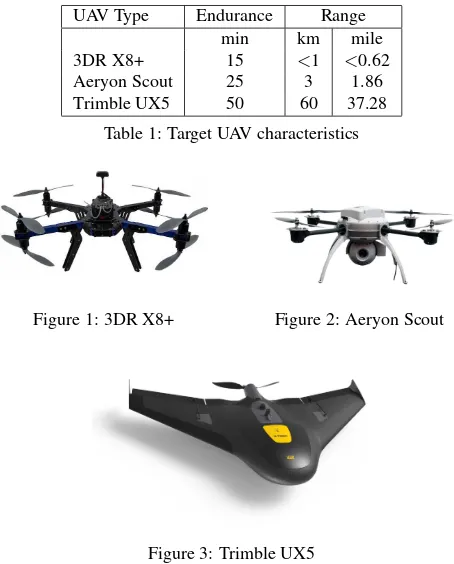
Figures 1, 2, and 3 show an example of the target UAVs, that can accommodate the proposed payload. The main characteristics of these UAVs are summarized in Table 1.
The three candidate UAVs can cover short range to medium range missions, and they can operate for 15 to 50 minutes. Knowing the endurance and range of target UAV is important when selecting the suitable communication module, as will be illustrated in a fol-lowing section. It is worth noting that when planning a UAV fly-ing mission, the major limitation to the flight range could be the regulations in effect (Toth and Jkw, 2016), not just the hardware constraints of the UAV system.
UAV Type Endurance Range
min km mile
3DR X8+ 15 <1 <0.62
Aeryon Scout 25 3 1.86
Trimble UX5 50 60 37.28
Table 1: Target UAV characteristics
Figure 1: 3DR X8+ Figure 2: Aeryon Scout
Figure 3: Trimble UX5
2.2 Synchronization Error Analysis
Synchronization error is one of the errors that contaminates the calculated coordinates of a certain pointiin the mapping frame (El-Sheimy, 1996; Skaloud, 1999). This error is caused by the fact that each sensor used in the system has its own time refer-ence. The objective of implementing a hardware-based synchro-nization solution is to establish a common timing reference be-tween the imaging sensors, and the positioning solution. Then, use this reference to accurately time-tag all sensors output.
In order to define the required synchronization resolution, the ef-fect of the synchronization error should be examined. The follow-ing analysis defines the error of the computed ground coordinates of a pointi, measured using camera and lidar data, as a function of the synchronization error between the imaging device and the positioning solution.
Using camera data, the ground coordinates of the pointiin the mapping frame is given by Equation 1.
rmi =r
i – ground coordinates of the pointiin the map-ping frame
rmGP S(t)– GPS antenna phase center position
rb c, r
b
GP S– offset between the camera/GPS antenna phase center and the IMU in the body frame
si– pointiscale factor
Rmb(t) – rotation matrix between the body frame and the mapping frame
Rb
c– rotation matrix between camera frame and the body frame
rc
i(t)– coordinates of pointiin the camera frame
The coordinates error,δrim, due to synchronization error can be obtained by introducing the synchronization error term, δt, to Equation 1. To derive theδrm
i term, we expand the right hand side of Equation 2 around the correct image capturing time,ti, and we consider the first two derivatives of the GPS position,
rm
GP S(t), and the first derivative of rotation matrix R m b (t), as shown in Equation 3.
Equation 4 shows the final expression of the ground coordinates error for a pointi, whereR˙m
b (ti) =Rmb(ti)Ωbmb. For traditional airborne based mapping, only the first term of the error equation is considered (Skaloud, 1999). Figure 4 shows the coordinates error for a fixed-wing UAV flight, with a synchronization error of 1ms. The effect of the rotation matrix error, Rm
b (t), is in the same order of magnitude of the velocity error. Figure 4 shows also that the effect of the UAV vibration on the final coordinates error is insignificant.
A similar analysis can be performed to evaluate the impact of syn-chronization error on the ground coordinates of scanned points by a lidar system. The lidar derived ground coordinates of pointiis given by Equation 5. Using the same approach described earlier, the final coordinates error,δrm
i , considering the impact of time synchronization error is given by Equation 6.
rmi =r
where rblu– offset between the laser unit and the IMU in the body frame
Rb
lu– rotation matrix between laser unit frame and the body frame
Rlulb(t)– rotation matrix between laser beam frame and the laser unit frame
δrim= ˙r m
GP S(ti)δt+ 1 2r¨
m GP S(ti)δt
2
+Rmb (ti)Ω b mbδt
×
rlub −rGP Sb +R b lur
lu lbr
lb i(ti)
(6)
Figure 5 shows the impact of time synchronization error on the simulated lidar point cloud coordinates. This figure shows the effect of1mssynchronization error between the lidar measure-ments and the GPS/INS position and orientation. The simulated data utilizes the Applanix POS LV 420 GPS/INS unit and the Velodyne HDL-32E lidar unit.
Figure 4: Norm of the image ground coordinates errors
Figure 5: Simulated lidar points errors
2.3 Computational Platform
The traditional computational platforms used in several UAV sys-tems are based on microcontrollers (Bumker et al., 2013; Mszars, 2011; Berni et al., 2009). They are low-cost, easy to program, and provide convenient I/O interfaces to connect several periph-erals. However, microcontroller have serious performance limi-tations, that prevent them from processing large amounts of data in real-time. They are mainly used for basic data logging and time-stamping.
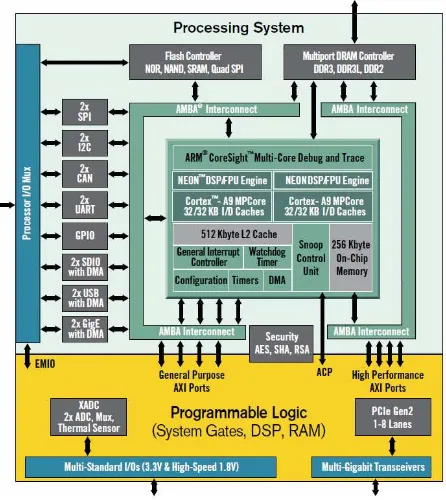
In order to enable the potential of real-time processing on the UAV, a more powerful and versatile computational platform is required to power the proposed payload. As a result, the pro-posed payload is built around the ZynqR
system-on-chip (SoC), from XilinxR
. This specific SoC was selected because it provides a powerful ARMR
CortexTM-A9 processor and a tightly con-nected programmable logic fabric. Figure 6 shows an overview
of the Zynq architecture. The Zynq platform has a lot of peripher-als; such as universal serial bus (USB), Ethernet, serial-peripheral interface (SPI), I2C interface, UART and general-purpose I/Os (GPIO). The Zynq platform can connect to high speed DDR3 memory, which provides sufficient memory to run an operating system, such as Linux, and to handle large amount of data.
The flexibility of the Zynq platform comes with a challenge. That is, working with the Zynq SoC and leveraging its full power re-quires a steep learning curve, and rere-quires knowledge in logic design and the corresponding logic design languages; such as VHDL or verilog. In conclusion, working with Zynq is not as easy as working with simple microcontrollers.
That said, Xilinx provides a complete design environment to fa-cilitate the implementation of the hardware and software compo-nents of the system. The tools chain includes a hardware inte-grated development environment, coupled with a logic simulator, and a complete tool chain to generate the binary stream required to configure the programmable logic and the processor. Further-more, the available tools comprise a software development kit (SDK), and a dedicated tool to configure and compile Linux op-erating system, which runs on the processing subsystem of the SoC.
The programmable logic devices from different manufacturers have been used in photogrammetry and computer vision appli-cations. One example is the system proposed by (Nikolic et al., 2014), in which the authors use a Zynq-based system for simulta-neous localization and mapping (SLAM) in robotics applications. The authors of (Zheng et al., 2014) use heterogeneous system, utilizing an FPGA and DSP+ARM processors, in order to achieve real-time photogrammetric processing system.
Figure 6: Zynq-7000 all programmable SoC block diagram
2.4 Payload Sensors
Figure 7: Canon PowerShot S110 camera
Figure 8: Velodyne HDL-32E LiDAR
and Ethernet connection, respectively. This allows for remote data exchange and control of their operation.
Each one of the two sensors has different bandwidth require-ments, according to the nature of generated data and its sampling rate. Table 2 summarizes the different data types generated by the sensors, the data rate, and the total required bandwidth. These fig-ures are an indication of which part of the generated data could be transmitted through the wireless link to the base station.
Data Type Size Data Rate Bandwidth
Byte Hz Byte/s Bit/s
JPEG Images ∼5 M 0.05 250 k 2000 k
RAW Images ∼13 M 0.05 650 k 5200 k
Point Range 3.14 700 k 2.2 G 17.6 G
Table 2: Sensors data types and bandwidth requirements
2.5 Wireless Module Selection
The wireless communication module is an essential part of the proposed payload. It is responsible for several key tasks: trans-mitting a subset of the captured data back to the ground control station, transmitting the system status signals to the ground sta-tion, and receiving control signals from the remote operator.
The selection of the wireless module is influenced by the required operation range and the amount of data to be transmitted and re-ceived. Tables 1 and 2 provide a summary of the operation pa-rameters for the proposed payload. It would be ideal to find a low-cost and compact wireless module that can transmit the cap-tured images and points to a ground base station continuously in real-time and within the entire range of the UAV. However, a sur-vey of the available components in the market, showed that, for our target price, transmitting all captured data in real-time is not feasible. The on-board processing algorithm should define which subset of the data is sent to the ground station and which part is stored and processed on-board.
3. SYSTEM IMPLEMENTATION AND INTEGRATION
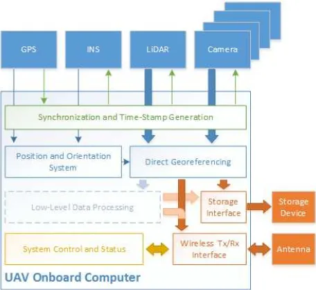
3.1 System Architecture
This section describes the overall architecture of the proposed payload. Figure 9 shows a block diagram of the payload. The sys-tem is composed of several sensors; such as GPS module, inertial measurement unit (IMU), lidar, and multiple cameras. These sen-sors are connected to the Zynq processing system (PS) through the carrier board, shown in Figure 11. The carrier board hosts the TE-0715-0-30 Zynq module board, shown in Figure 10. The carrier board also provides a wide array of I/O peripherals to the Zynq module. Both the carrier board and the Zynq module board are manufactured by Trenz Electronics GmbH (Trenz Electronic, 2016).
All sensors are connected to the carrier board. The two cam-eras are connected to the USB port, which provides the operator with full control over the camera and with access to the captured images on the fly as well. The details of the camera interface software are described in the subsequent section. The lidar is connected to the system through the Ethernet interface. The GPS and the IMU are connected to serial ports.
The GPS 1PPS signal, IMU interrupt signal, and cameras shutter synchronization signals are connected to the programmable logic (PL) section of the Zynq SoC through the PL I/O, which is re-ferred to as SelectIO (Technical Staff, 2015). The possibility of connecting signals directly to the Zynq PL allows the implemen-tation of custom logic blocks, to generate a reliable and a sta-ble internal timing reference, and to log the time of the different events occurring to the connected peripherals.
Figure 9: Payload system block digram
Figure 10: TE0715-03-30 Zynq SoC module XC7Z030
3.2 Camera Interface and Control
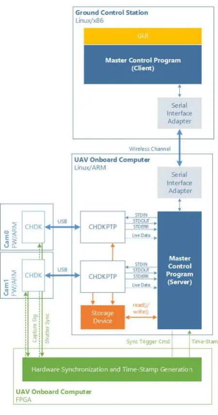
Figure 12 shows an overview of the camera interface. The cam-era interface makes us of the CHDK framework (CHDK, 2016). CHDK is an open source project, which enables advanced capa-bilities to the Canon point-and-shoot line of cameras. This in-cludes enabling RAW images capturing, controlling camera pa-rameters remotely, and many other advanced control functions found typically on high-end cameras.
Basically, CHDK is a software wrapper to the original Canon firmware. In our implementation we modified the CHDK code, to enable a more precise monitoring of the shutter operation. The modified code forces one of the LEDs on the camera body to ’ON’ state, just before the shutter opens, and then forces it back to ’OFF’ state right after the shutter closes. This enables more pre-cise time tagging of the actual image capturing process, not only the time the shooting command is sent from an external control device.
CHDK provides a basic solution to enable the synchronization of multiple cameras, using the USB port of the camera. Several so-lutions use this feature to synchronize different cameras, in which a hardware generated signal is used to trigger the image capturing process. However, using the standard USB synchronization fea-ture of CHDK prevents the user from accessing the data on the camera, or from controlling the camera functionality. The only way to enable and disable the USB synchronization feature is to do it manually through the camera user interface.
This limitation means that the camera cannot be controlled dur-ing the mappdur-ing mission, which significantly limits the usability of the system. Instead of using the standard synchronization fea-ture, our approach for controlling the camera is to send an image capture command through the USB control interface, and syn-chronize the shutter open time, as described in the previous para-graph.
CHDK provides an external software interface, called CHDK-PTP, which allows a host device to control the camera operation and perform data transfers, to and from the camera. The payload system makes use of CHDK-PTP by integrating the open-source interfacing software to our software solution.
Figure 12 gives an overview of camera interface architecture. Each camera runs CHDK firmware on its own processor. The cameras are paired with multiple instances of the CHDK-PTP software, hosted on the Zynq PS. The master camera control soft-ware is responsible for detecting the cameras, instantiating the CHDK-PTP interfaces, establishing the connection to the camera, and relaying the commands sent by the user to the correspond-ing camera, and interpretcorrespond-ing the camera response. This gives the operator a full control over the camera functionality, during the entire mapping mission.
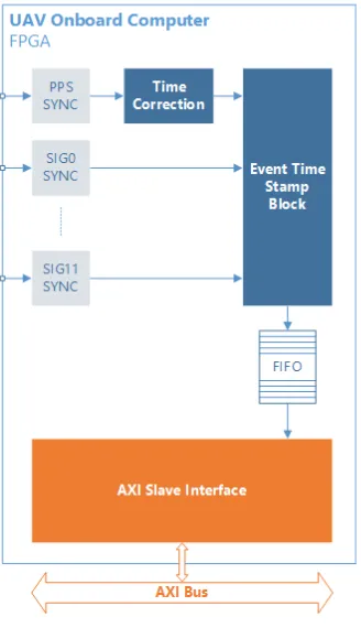
3.3 GPS Synchronized Data Logger
The data logging block is responsible for synchronizing the inter-nal clock of the Zynq PL to the GPS 1PPS siginter-nal, and for time-tagging the different peripherals trigger signals. Figure 13 shows a block diagram of the data logger block. The data logger block is composed of two major sub-blocks. The first is responsible for establishing the relation between the GPS 1PPS signal and the internal high-speed clock. The ’Time Correction’ block is count-ing how many cycles of the fast on-chip clock are there in one cycle of the 1PPS signal. This number is stored with several flags to indicate the health of the 1PPS counter. Specifically, to indi-cate whether an overflow has been occurred in the counter or not,
Figure 12: Camera interface overview
and to indicate that the counter output is ready to be used by the system software.
The second part of the data logger block is the ’Time Stamping’ block. This block monitors several input ports, each correspond-ing to a specific peripheral device. When one of these signals is triggered, the data logger block records the event time, using the high speed clock, and stores the unique peripheral ID associated with the triggered event.
The different data words are stored inside a FIFO, which is con-nected through a Slave AXI logic to the main AXI bus. The AXI bus provides a fast interface between the PL and the PS parts of the Zynq SoC (Technical Staff, 2015). This bus enables a soft-ware running on the ARM processor to interact with the hardsoft-ware blocks implemented on the PL side of the Zynq.
Figure 14 shows the results of using the ’Time Correction’ block to detect the actual frequency of the on-chip clock. The nominal value of the clock is set to 50 MHz. However, as this experiment shows, the actual clock frequency of the on-chip clock is more the nominal value by 6.17 ppm, with standard deviation of59.52×
10−3
Figure 13: Data logger architecture
Figure 14: On-Chip clock measurements
4. CONCLUSIONS AND FUTURE WORK
This paper presents the architecture and implementation details of a UAV imaging payload geared towards the time/near real-time mapping applications for disasters and emergency situations. The paper describes the main components of the system, and out-lines the system architecture. The implementation details of the two major building blocks of the system are presented in details; the camera interface block and the GPS synchronized data logger.
The objective of this work is to enable real-time/near real-time mapping applications. The proposed system is still a work-in-progress, and more work has to be done on different fronts, to achieve the required mapping performance:
• Migrating some of the photogrammetric algorithms to the
Zynq PS. This task requires rewriting the algorithms to meet the real-time execution requirements, and adapting them to leverage the ARM processor resources.
• Breaking down the photogrammetric algorithms into parts
that would be implemented as software and run on the Zynq PS, and another part that would be implemented as hardware to run on the Zynq PL. And, investigate the performance gains attained by the software-hardware partitioning.
ACKNOWLEDGEMENTS
This work was supported by Dr. Naser El-Sheimy research funds from the The Natural Sciences and Engineering Research Council of Canada (NSERC) and Canada Research Chairs programs. The data used for generating Figure 4 is provided by the Norwegian Research Council (projects no. 221666 and 223254) through the Center of Autonomous Marine Operations and Systems (AMOS) at the Norwegian University of Science and Technology.
REFERENCES
Berni, J. A. J., Zarco-Tejada, P. J., Surez, L., Gonzlez-Dugo, V. and Fereres, E., 2009. Remote sensing of vegetation from UAV platforms using lightweight multispectral and thermal imaging sensors. Int. Arch. Photogramm. Remote Sens. Spatial Inform. Sci.
Bumker, M., Przybilla, H. and Zurhorst, A., 2013. Enhancements in UAV flight control and sensor orientation. Proceedings of the International Archives of Photogrammetry, Remote Sensing and Spatial Information Science (UAV-g 2013), Rostock, Germany pp. 4–6.
CHDK, 2016. CHDK Wiki. http://chdk.wikia.com/wiki/CHDK. (1 Apr. 2016).
El-Sheimy, N., 1996. The development of VISAT-A mobile sur-vey system for GIS applications. PhD thesis, University of Cal-gary.
Lari, Z. and El-Sheimy, N., 2015. System Considerations and Challenges in 3d Mapping And Modeling Using Low-Cost UAV Systems. ISPRS - International Archives of the Photogramme-try, Remote Sensing and Spatial Information Sciences XL-3/W3, pp. 343–348.
Mszars, J., 2011. Aerial surveying UAV based on open-source hardware and software. In: Zurich: Conference on Unmanned Aerial Vehicle in Geomatics.
Nikolic, J., Rehder, J., Burri, M., Gohl, P., Leutenegger, S., Fur-gale, P. T. and Siegwart, R., 2014. A synchronized visual-inertial sensor system with FPGA pre-processing for accurate real-time SLAM. In: Robotics and Automation (ICRA), 2014 IEEE Inter-national Conference on, IEEE, pp. 431–437.
Skaloud, J., 1999. Problems in direct-georeferencing by INS/DGPS in the airborne environment. In: ISPRS, Workshop on” Direct versus indirect methods of sensor orientation”, Com-mission III, WG III/1, Barcelona, Spain.
Technical Staff, 2015. Zynq-7000 All Programmable SoC: Tech-nical Reference Manual (UG585). 1.10 edn, Xilinx.
Toth, C. and Jkw, G., 2016. Remote sensing platforms and sen-sors: A survey. ISPRS Journal of Photogrammetry and Remote Sensing 115, pp. 22–36.
Trenz Electronic, 2016. TE0715 Product Information. http://www.trenz-electronic.de/products/fpga-boards/trenz-electronic/te0715-zynq.html. (14 Apr. 2016).