Approval Date: 2015-06-04
Publication Date: 2015-10-01
External identifier of this OGC® document: http://www.opengis.net/doc/BP/COP-for-oil-spill/1.0
Internal reference number of this OGC® document: OGC 15-037
Version: 1.0
Category: OGC® Best Practice
Editor: George Percivall
OGC IOGP/IPIECA Recommended Practice for a
Common Operating Picture for Oil Spill Response
Copyright notice
Copyright © 2015 Open Geospatial Consortium
To obtain additional rights of use, visit http://www.opengeospatial.org/legal/.
Warning
This document is not an OGC Standard. This document is distributed for review and
comment. This document is subject to change without notice and may not be referred
to as an OGC Standard.
Recipients of this document are invited to submit, with their comments, notification
of any relevant patent rights of which they are aware and to provide supporting
documentation.
Document type: OGC® Best Practice Document subtype: not applicable Document stage: Final
2
below, to any person obtaining a copy of this Intellectual Property and any associated documentation, to deal in the Intellectual Property without restriction (except as set forth below), including without limitation the rights to implement, use, copy, modify, merge, publish, distribute, and/or sublicense copies of the Intellectual Property, and to permit persons to whom the Intellectual Property is furnished to do so, provided that all copyright notices on the intellectual property are retained intact and that each person to whom the Intellectual Property is furnished agrees to the terms of this Agreement.
If you modify the Intellectual Property, all copies of the modified Intellectual Property must include, in addition to the above copyright notice, a notice that the Intellectual Property includes modifications that have not been approved or adopted by LICENSOR.
THIS LICENSE IS A COPYRIGHT LICENSE ONLY, AND DOES NOT CONVEY ANY RIGHTS UNDER ANY PATENTS THAT MAY BE IN FORCE ANYWHERE IN THE WORLD.
THE INTELLECTUAL PROPERTY IS PROVIDED "AS IS", WITHOUT WARRANTY OF ANY KIND, EXPRESS OR IMPLIED, INCLUDING BUT NOT LIMITED TO THE WARRANTIES OF MERCHANTABILITY, FITNESS FOR A PARTICULAR PURPOSE, AND NONINFRINGEMENT OF THIRD PARTY RIGHTS. THE COPYRIGHT HOLDER OR HOLDERS INCLUDED IN THIS NOTICE DO NOT WARRANT THAT THE FUNCTIONS CONTAINED IN THE INTELLECTUAL PROPERTY WILL MEET YOUR REQUIREMENTS OR THAT THE OPERATION OF THE INTELLECTUAL PROPERTY WILL BE UNINTERRUPTED OR ERROR FREE. ANY USE OF THE INTELLECTUAL PROPERTY SHALL BE MADE ENTIRELY AT THE USER’S OWN RISK. IN NO EVENT SHALL THE COPYRIGHT HOLDER OR ANY CONTRIBUTOR OF INTELLECTUAL PROPERTY RIGHTS TO THE INTELLECTUAL PROPERTY BE LIABLE FOR ANY CLAIM, OR ANY DIRECT, SPECIAL, INDIRECT OR CONSEQUENTIAL DAMAGES, OR ANY DAMAGES WHATSOEVER RESULTING FROM ANY ALLEGED INFRINGEMENT OR ANY LOSS OF USE, DATA OR PROFITS, WHETHER IN AN ACTION OF CONTRACT, NEGLIGENCE OR UNDER ANY OTHER LEGAL THEORY, ARISING OUT OF OR IN CONNECTION WITH THE IMPLEMENTATION, USE, COMMERCIALIZATION OR PERFORMANCE OF THIS INTELLECTUAL PROPERTY.
This license is effective until terminated. You may terminate it at any time by destroying the Intellectual Property together with all copies in any form. The license will also terminate if you fail to comply with any term or condition of this Agreement. Except as provided in the following sentence, no such termination of this license shall require the termination of any third party end-user sublicense to the Intellectual Property which is in force as of the date of notice of such termination. In addition, should the Intellectual Property, or the operation of the Intellectual Property, infringe, or in LICENSOR’s sole opinion be likely to infringe, any patent, copyright, trademark or other right of a third party, you agree that LICENSOR, in its sole discretion, may terminate this license without any compensation or liability to you, your licensees or any other party. You agree upon termination of any kind to destroy or cause to be destroyed the Intellectual Property together with all copies in any form, whether held by you or by any third party.
Work Package 5: Common
Operating Picture
Recommended practice for Common Operating
Picture architecture for oil spill response
FINAL REPORT
The global oil and gas industry association for environmental and social issues 5th Floor, 209–215 Blackfriars Road, London SE1 8NL, United Kingdom Telephone: +44 (0)20 7633 2388 Facsimile: +44 (0)20 7633 2389 E-mail: [email protected] Internet: www.ipieca.org
International Association of Oil & Gas Producers
London office
5th Floor, 209–215 Blackfriars Road, London SE1 8NL, United Kingdom Telephone: +44 (0)20 7633 0272 Facsimile: +44 (0)20 7633 2350 E-mail: [email protected] Internet: www.iogp.org.uk
Brussels office
Boulevard du Souverain 165, 4th Floor, B-1160 Brussels, Belgium Telephone: +32 (0)2 566 9150 Facsimile: +32 (0)2 566 9159 E-mail: [email protected] Internet: www.iogp.org.uk
©IOGP/IPIECA 2015 All rights reserved.
No part of this publication may be reproduced, stored in a retrieval system, or transmitted in any form or by any means, electronic, mechanical, photocopying, recording or otherwise, without the prior consent of IPIECA.
Disclaimer
Abstract
Responding to an oil spill requires access to and understanding of many types of information. Effective, coordinated operations for the response are based on a shared, common picture of the situation. Interoperability provides shared situational awareness of the crisis and the response activities. What is needed is a common picture of reality for different organizations that have different views of the spill so that they all can deal with it collectively.
Recent oil spills have provided lessons learned and recommendations on forming a Common Operating Picture for oil spill response. Through a joint project, industry is responding to the call, moving from recommendations to reusable best practices supported by open standards that can be deployed quickly in any region of the globe.
This architecture report is part of The International Association of Oil & Gas Producers and IPIECA Oil Spill Response - Joint Industry Project (IOGP–IPIECA OSR-JIP) to produce a recommended practice for GIS/mapping in support of oil spill response and for the use of GIS technology and geospatial information in forming a “Common Operating Picture” to support management of the response.
Table Of Contents
Abstract
... iii
Table Of Contents
... iv
Introduction
... 1
Scope of this report ... 1
Oil Spill Response Joint Industry Project ... 1
Organizations preparing this report ... 3
Architecture viewpoints used in this document ... 4
COP Enterprise Viewpoint
... 5
Observations about Deepwater Horizon ... 5
Establishing an oil spill response COP ... 6
Users and developers of the COP ... 10
Scenarios for use of a COP ... 13
Enterprise components for COP ... 19
COP Information Viewpoint
... 20
The COP information landscape ... 20
Geospatial information ... 23
Planning considerations ... 24
Geospatial information standardization and organization ... 26
Map templates list ... 33
Data modeling ... 36
Geospatial information datasets ... 37
COP Services Viewpoint
... 55
Funneling information to the COP for users ... 55
Requirements for the Services Viewpoint ... 56
Displaying the COP to users ... 56
Web services for delivering the COP ... 59
Spatial analysis services in the Response Center ... 63
Inputs to the Response Center ... 63
Disconnected user operations ... 71
COP Deployment Viewpoint
... 72
Preparing for deployment before the incident ... 72
Clients ... 73
Client networks (including security) ... 74
Response Center components ... 74
Source layer components ... 75
Annex A. Oil Spill Response COP datasets
... 76
List of Figures
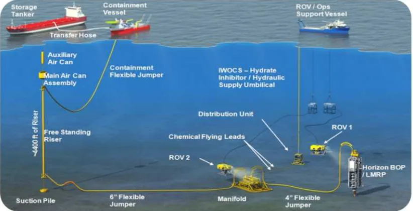
Figure 1 Typical subsea well intervention project ... 2
Figure 2 Common Operating Picture - highlighting geospatial information ... 6
Figure 3 Geographic setting and source of spills ... 7
Figure 4 Incident lifecycle ... 8
Figure 5 Potential COP users ... 11
Figure 6 Organizational structure of an IMS ... 12
Figure 7 Enterprise components of COP platform ... 19
Figure 8 Data access model ... 21
Figure 9 Map/chart symbology for incident response ... 30
Figure 10 Symbols for the mapping of sensitive biological resources ... 31
Figure 11 Color code of Environmentally Sensitive Index ... 31
Figure 12 Symbols for the mapping of sensitive human use and activities ... 32
Figure 13 Oil spill trajectory model ... 48
Figure 14 COP workflow process ... 55
Figure 15 An example of an oil spill response COP geospatial dashboard ... 57
Figure 16 COP service-oriented architecture ... 59
Figure 17 Surveillance observation request process ... 65
Figure 18 COP component deployment architecture ... 73
Figure 19 Diversity of deployment platforms ... 74
List of Tables
Table 1 Incident lifecycle phase 0 – Preparation ... 8Table 2 Incident lifecycle phase 1 – Mobilization ... 9
Table 3 Incident lifecycle phase 2 – Containment and Cleanup ... 9
Table 4 Incident lifecycle phase 3 - Restoration and Return to Normal Operations ... 9
Table 5 Oil spill response COP datasets ... 76
Introduction
Scope of this report
This report provides an architecture for creating a Common Operating Picture (COP) for use during a response to an oil spill. This report provides recommended practice for the implementation of an effective COP and the requisite data management by the response community.
The report was prepared as part of a project to assess the current state of standards and implementations that could support recommendations regarding a COP for use during an oil spill response (OSR). It has been compiled after a Request for Information (RFI) process based on an initial document developed by the organizations mentioned in Section 1.3, followed by two industry workshops (in Houston and in London) where oil & gas companies, vendors and suppliers, academia, and regulators participated and provided valuable contributions, which were taken into account when developing this version 1 of the Recommended Practice.
Future versions of this Recommended Practice are expected after further work is done at an industry level to develop common data models/schema and standards, to support a more effective implementation of a COP.
Oil Spill Response Joint Industry Project
The April 2010 Gulf of Mexico (Macondo/Deepwater Horizon) oil spill incident, and the Montara incident in Australia which preceded it, have had far-reaching consequences in prompting the re-examination by industry not only of operational aspects of offshore operations, but also of an operator’s ability to respond in the event of an oil spill incident or well blowout (Figure 1).
In response to the foregoing, the International Association of Oil and Gas Producers (IOGP) formed the Global Industry Response Group (GIRG), tasked with identifying learning opportunities both on causation and in respect of the response to the incident. Nineteen recommendations were identified and these are being addressed via a three-year Oil Spill Response - Joint Industry Project (OSR-JIP) funded by oil industry members1.
1
Figure 1 Typical subsea well intervention project
Source: Oceaneering, 2014
The OSR-JIP has initiated discreet projects or provided support to projects initiated by other trade associations in the nineteen subject areas resulting from the IOGP GIRG
recommendations. The OSR-JIP is managed by IPIECA on behalf of IOGP in recognition of its long-standing experience with oil spill response matters.
The OSR-JIP is composed of several work streams. This project forms part of JIP 8, 10, 11, & 16: Surveillance, Modelling & Visualization and is entitledWork Package 5 (WP5) - GIS/Mapping and Common Operating Picture.
The aim for WP5 was to produce a recommended practice for the use of GIS and mapping in support of oil spill response and for the use of GIS technology and geo-information in forming a “Common Operating Picture” for management of the response.
WP5 should identify:
• What data needs to be available?
• Where does it come from?
• What format should it be in, and to what spatial accuracy?
• How should it be delivered, and to whom?
• How should it be archived and preserved.
WP5 is being conducted in close coordination with a number of other WPs that are part of
JIP 8, 10, 11, & 16: Surveillance, Modelling & Visualization:
• WP1 - In-Water Surveillance
• WP2 - Surface Surveillance
• WP3 - Modelling & Prediction
• WP4 - Metocean Databases
• WP6 - Regulatory Issues
• WP7 - Report Deliverable
Organizations preparing this report
The International Association of Oil & Gas Producers (IOGP)2 is a unique global forum in
which members identify and share best practices to achieve improvements in every aspect of health, safety, the environment, security, social responsibility, engineering and operations. IOGP encompasses most of the world's leading publicly traded, private and state-owned oil & gas companies, industry associations and major upstream service companies. IOGP members produce more than half the world's oil and about one third of its gas.
IPIECA3 is the global oil and gas industry association for environmental and social issues.
IPIECA was formed in 1974 following the launch of the United Nations Environment Programme (UNEP). IPIECA is the only global association involving both the upstream and downstream oil and gas industry on environmental and social issues. IPIECA’s membership covers over half of the world’s oil production. IPIECA is the industry’s principal channel of communication with the United Nations. When IPIECA was set up in 1974 the acronym stood for the International Petroleum Industry Environmental Conservation Association. In 2009, recognizing that this no longer accurately reflected the breadth and scope of the association’s work, IPIECA stopped using the full title. The association is now known as IPIECA, the global oil and gas industry association for environmental and social issues.
Resource Data, Inc.4 (RDI) has been supporting the oil & gas industry with information
technology for spill response since 1989. RDI brings unparalleled experience to oil spill response, leading the geographic information system (GIS) and database teams for the Exxon-Valdez spill and more recently the GIS response team in the Macondo/Deepwater Horizon spill. RDI has developed numerous spill response data systems, participated in multiple drills, and developed risk analysis systems for major pipeline networks. Our depth and breadth of expertise in spill preparedness and response uniquely positions RDI to assist in the development of a COP for the oil & gas industry.
2 International Association of Oil and Gas Producers website. See: http://www.iogp.org/ 3 IPIECA website. See: http://www.ipieca.org/
The Open Geospatial Consortium (OGC)5 is an international consortium of more than 480
companies, government agencies, research organizations, and universities participating in a consensus process to develop publicly available geospatial standards. OGC standards support interoperable solutions that "geo-enable" the web, wireless and location-based services, and mainstream IT. OGC standards empower technology developers to make geospatial information and services accessible and useful with any application that needs to be geospatially enabled.
Architecture viewpoints used in this document
This report provides a technical description of a COP for oil spill response using an architecture perspective. The organization of this technical description is based on ISO/IEC 10746, Information Technology — Open Distributed Processing — Reference Model. RM-ODP defines viewpoints that separate the various concerns when developing an information system architecture.
• Section 2 of the report provides an Enterprise Viewpoint, including a definition of a COP, the target audience (Users) and stakeholders, and example Use Case scenarios.
• Section 3 provides an Information Viewpoint, outlining the specific information and data that is delivered through the COP, and the basic governing principles.
• Section 4 outlines the computational Services Viewpoint, including interfaces and workflows pertinent to a COP using a service oriented architecture.
• Section 5 provides a Deployment Viewpoint, identifying the key types of components required to support the deployment, management and integration of the services and data.
5
COP Enterprise Viewpoint
Observations about Deepwater Horizon
Accurate, timely, and geo-referenced information is vital to operational and strategic decision-making. The Deepwater Horizon incident created an unprecedented need for information on a real-time basis. Barriers to synchronized and total domain awareness during the Deepwater Horizon incident included:
• Lack of agreement on what data needed to be tracked and transmitted;
• Vast geography of the response area of operations;
• Lack of availability of appropriate interoperable communications technology;
• Limited ability to push real-time data, both vertically and laterally, throughout the response organization;
• Different computing standards.
The incompatibility of proprietary databases and software used by the private sector appeared to be a hindrance to developing a universal COP for the response organization. Integrating data from multiple restricted sources slowed the development of a complete and an accurate COP.
The demand for information within Deepwater Horizon however drove an evolution of knowledge management and the response eventually established a strong COP, which provided for more effective communication throughout the response organization. An efficient information flow that met the needs of both the response organization and senior officials was also established, however there remained significant scope for improvement.
Many of those interviewed specifically stated that the National Incident Management System/Incident Command System (ICS) worked as intended. Because NIMS/ICS is scalable, adaptive, and dynamic, responders were able to tailor the response organization according to need. The ‘Deepwater Horizon Incident Specific Preparedness Review’ (ISPR6)
provides recommendations that serve to further enhance NIMS/ICS use in future spills.
Based on lessons learned from the Deepwater Horizon oil spill response, a Notice To Lessees (NTL) was issued by the US Bureau of Safety and Environmental Enforcement (BSEE) providing ‘Guidance to Owners and Operators of Offshore Facilities Seaward of the Coast Line Concerning Regional Oil Spill Response Plans’7. The NTL provides clarification,
guidance, and information concerning the preparation and submittal of a regional Oil Spill Response Plan (OSRP) for Oil and Gas Operators in the Gulf of Mexico.
6 ‘Final Action Memorandum - Incident Specific Preparedness Review (ISPR) Deepwater Horizon Oil Spill’, US
Coast Guard, March 18, 2011. See: https://www.uscg.mil/foia/docs/DWH/BPDWH.pdf
7 BSEE Notice to Lessees Number 2012-N06, 10 August 2012. See:
The NTL encouraged lessees to specify primary and alternate communications technology and software for use when coordinating and directing oil spill response operations and/or providing a Common Operating Picture to all oil spill management and response personnel, including the Federal On-Scene Coordinator and participating federal and state government officials.
Establishing an oil spill response COP
Definition of a COP
After consideration of several definitions provided by various parties, the following is considered to provide a concise definition of a Common Operating Picture:
A Common Operating Picture (COP) is a computing platform based on Geographical Information System (GIS) technology that provides a single source of data and information for situational awareness, coordination, communication and data archival to support emergency management and response personnel and other stakeholders involved in or affected by an incident.
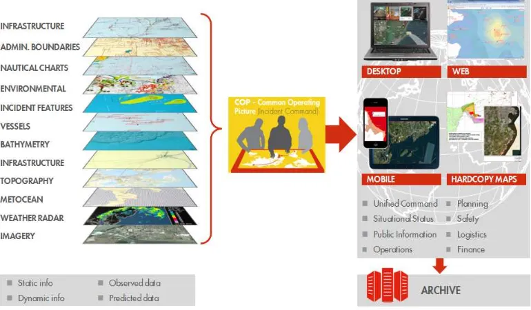
Figure 2 provides a summary graphical perspective of a COP for responding to an oil spill.
Figure 2 Common Operating Picture - highlighting geospatial information
In addition to the COP, an incident command will use other information technology (IT) tools and systems to support processes such as equipment and services procurement, internal and external communications, asset management, invoice/payments, claims and recovery, reporting, and so forth. Such systems are commercially available and are evolving in capability to include basic COP functionality.
Integration of the COP with such systems is encouraged to facilitate information flow and simplify information management processes. However, the need to access high quality, reliable geospatial data from a variety of sources - including data that is proprietary to the oil company or its service providers - may necessitate that the COP is delivered and operated externally to these systems/tools. The interoperability standards that will form part of this guideline are designed to ensure that geospatial data can be integrated whilst applying appropriate levels of data security.
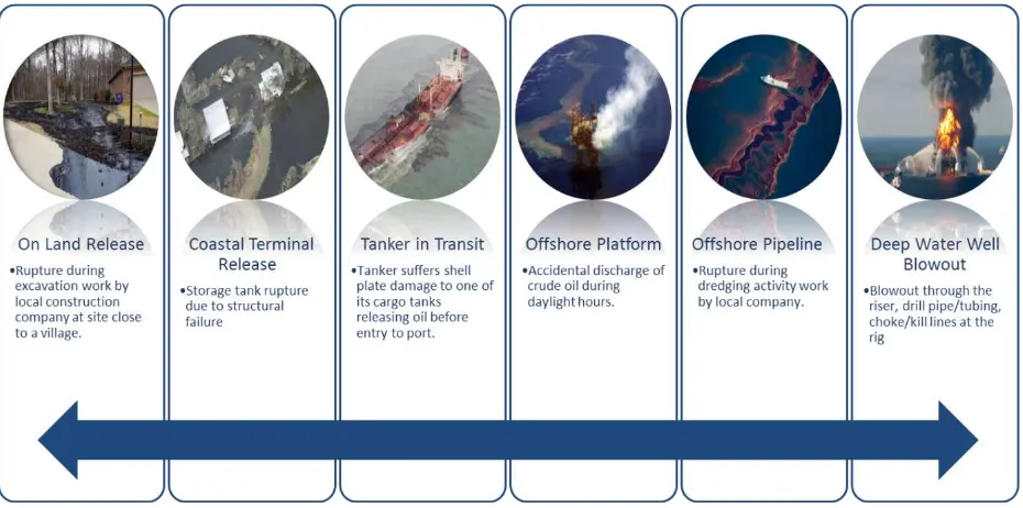
Geographic setting and source of spill
To understand how a COP can be used in a response it is important to understand the types of oil spill events targeted in this recommended practice. Figure 3 shows a set of scenarios in which a COP would be critical for effective Emergency Response.
Figure 3 Geographic setting and source of spills
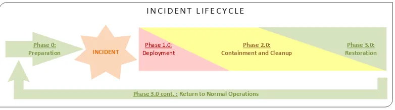
Incident lifecycle
Lifecycle overview
The needs and focus of data-related activities change through the phases of a spill. For the purpose of information management only, we have defined the life cycle of a spill as shown in Figure 4.
Figure 4 Incident lifecycle
Source: IPIECA–IOGP, 2015
Phase 0 – Preparation
This phase is characterized by planning, data identification and acquisition, and drills.
Table 1 Incident lifecycle phase 0 – Preparation
Activities Completion Criteria
• Operations in new geographic areas.
• Changes in organizational technology and technology strategy.
• Changes to data sources.
• New tools becoming available.
• COP Information Management Plan template prepared.
• Response plan is complete (including data archiving).
• All required datasets should be identified.
• Base data should be acquired .
• All tools should be on hand.
• Staff should be assigned and trained in their specific ICS roles.
Phase 1 – Mobilization
Initial response activities are the primary focus of this phase, and minimizing the time of response is the key theme. The focus of this phase is damage limitation, resource acquisition, and building and implementing teams.
I N C I D E N T ' L I F E C Y C L E
Phase&3.0&cont.&:&Return&to&Normal&Operations
INCIDENT
Phase&0: Preparation
Phase'1.0:' Deployment
Phase&2.0:& Containment&and&Cleanup
Table 2 Incident lifecycle phase 1 – Mobilization
Activities Completion Criteria
• Incident command center initiated.
• Resources identified and initially gathered.
• Communications lines established.
• Data access and sharing at various levels of technology (web services, hardcopy forms, response repository).
• Information Management Plan implemented here.
• Initial Geomatics Unit is in place.
• Roles and accountabilities are assigned.
• Infrastructure is in place and operational.
• Software tools are installed and available to users.
• Data structures are implemented and populated (base data) or available for population (incident data).
• Communications to all stakeholders is established.
• Archiving strategy is implemented and data is being backed up and archived.
Phase 2 – Containment and cleanup
Containment and cleanup is entered into as soon after an incident as possible. Typically, it will begin concurrently to Mobilization but will continue after mobilization is complete.
Table 3 Incident lifecycle phase 2 – Containment and Cleanup
Activities Completion Criteria
• Data loading.
• Production of outputs based on templates.
• Data backups.
• Periodic snapshots taken.
• Ad-hoc data requests fulfilled by on-site staff.
• Containment and cleanup activities are shut down.
Phase 3 – Restoration and return to normal operation
The final stages of a response are restoration and then returning to normal operations.
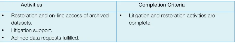
Table 4 Incident lifecycle phase 3 - Restoration and Return to Normal Operations
Activities Completion Criteria
• Restoration and on-line access of archived datasets.
• Litigation support.
• Ad-hoc data requests fulfilled.
COP Information Management Plan
An Information Management Plan (IMP) should be developed at the beginning of any oil spill response using a standardized template prepared before the incident. This document would lay the groundwork for information management and data sharing across the response. It would include agreed upon data standards, field reporting requirements, media formats, as well as data archiving.
In order for a COP to function effectively, it must provide operational information in near real
-time. This requires not only system continuity but also structure in the response organization to facilitate communication among the appropriate responders. Formalized ICS positions for information management are needed. In particular experts for geospatial information and remote sensing are needed either in the response or on call.
Information available during the incident response needs to be retained for activities after the incident. Activities include maintaining accurate and comprehensive incident files, including a complete record of the major steps taken to resolve the incident as well as storing incident files for legal, analytical, and historical purposes. Snapshots of the COP and the Response Center database need to be made on a periodic basis and transferred to a location remote from the Response Center.
Information release process
Different users of the COP may have access to differing information based on access control. Access is provided to the data through role-based security established prior to the event. Access control is the selective restriction of access to resources. An access control policy is established as part of the COP information release process. The policy is then implemented as part of the deployment of the COP. Access control can involve authorization of access based on authentication of the user using a credentials system.
User Identity and Management Services as deployed, for example in a web services environment for the COP, is discussed further below in this report.
Users and developers of the COP
Categories of users
A COP is established and maintained by gathering, collating, synthesizing, and
disseminating incident information for all appropriate parties. A COP potentially allows on-scene and off-on-scene personnel to have the same information about the incident including the availability and location of resources and the status of assistance requests.
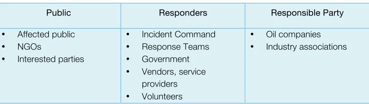
COP users are categorized as:
1) Public (including media and academia) 2) Responders (including the Response Center) 3) Responsible Party
ICS organization roles
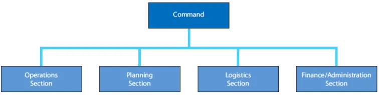
Experience has demonstrated the value of integrating incident response functions and resources into a single operational organization, managed and supported by one command structure and supporting processes. The IPIECA–IOGP ‘Incident Management System for the Oil and Gas Industry’ Good Practice Guide (IMS-GPG, IPIECA–IOGP, 2014)8 provides
experienced-based good practice guidelines for incident management and emergency response personnel. IMS-GPG is based on the Incident Command System (ICS), a version of IMS that is widely used by industry, response contractors and professional emergency services organizations. An IMS includes a set of proven organizational and management principles including common organizational elements (e.g. sections, branches, divisions, etc.), management structure, terminology and operating procedures.
The IPIECA–IOGP good practice guidelines define an organizational structure for an IMS to include four major sections under the Command function: Operations, Planning, Logistics and Finance/Administration (Figure 6).
8 ‘Incident Management System for the Oil and Gas Industry: Good practice guidelines for incident management
and emergency response personnel’, IPIECA–IOGP, IOGP Report Number 517, August 2014.
Figure 5 Potential COP users
Public Responders Responsible Party
• Affected public
• NGOs
• Interested parties
• Incident Command
• Response Teams
• Government
• Vendors, service providers
• Volunteers
• Oil companies
Figure 6 Organizational structure of an IMS
Source: IMS-GPG, IPIECA–IOGP, 2014
Geomatics Unit of ICS Planning Section
Given the pervasive and critical role of geospatial information to the COP for the response, it is recommended that a Geomatics Unit be defined within the Planning Section of the ICS structure.
The Geomatics Unit oversees the management and collection of spatial data; provides mapping, spatial analysis and meeting support for the response. The unit also develops, manages, and updates the Common Operation Picture.
Roles within the Geomatics Unit include:
• Geomatics Liaison – this role serves as a single POC within the command post that accepts and officially documents requests on an ICS-form, and then delegates out the work to information analysts. The person sitting in this role must be fluent in geo-information to weed out inappropriate requests and understand basic deliverable timelines for information products. This role serves as the data manager for geo-information. They also could serve as the role of oversight for any response GIS database and/or “working” data repository. They would work with the incident documentation unit to make sure that the correct information is collected and that the responders have access to it.
• Common Operating Picture Lead – this role publishes and updates the Common Operating Picture as the incident unfolds and attends official meetings to ‘drive’ the COP to support the talking points of the meeting. This role will also support briefings to executive leadership, the media, and local, state, federal authorities.
• Geo-information Analyst – this role performs mapping and analysis on request from the liaison. The role may also take direct assignment or embed with other sections such as Operations or Logistics. Cartography expertise may be included in this role.
• Geomatics Operations Specialist – arranges, specifies and coordinates survey operational activities required in support of the incident, including mobilizing survey equipment, vessels and resources, and overseeing safe operations. Geodesy and hydrography expertise may also be included in this role.
• Metocean Specialist – this role provides specialist technical expertise in the acquisition and interpretation of meteorological and oceanographic data and models in support of oil spill prediction and forecasting, in–situ measurements, and operational and logistic planning.
Scenarios for use of a COP
The following section outlines various scenarios for use of the COP within IMS.
Command Section use
The COP is the primary tool used for conducting daily command briefings during a response. A properly designed and implemented COP will visually show real-time or near real-time information within the area of responsibility (AOR). This will allow command staff to make decisions based upon actual and up-to-date information from the various sections of the response. The COP can be adapted and updated to meet the particular needs of a response, which often change due to the physical and political environment. Information present should include any datasets the command wants to see, report on, and discuss.
This may include:
• Satellite and aerial information
• Remotely Operated Vehicles (ROV) and Autonomous Underwater Vehicles (AUV) data and video feeds
• Real-time vessel locations from Automatic Identification System (AIS) feeds
• Oil plume versus oil trajectory
• Digital geo-tagged photographs of cleanup operations
• Shoreline Cleanup and Assessment Technique (SCAT) data
• Dispersant use data
• Boom locations (planned and actual)
• Skimming data
• In-situ burn information
• Wildlife sightings (dead and alive)
• Anything else Command is interested in seeing
Command should use the COP for reporting and analyzing the data. Examples include:
• Percentage of shoreline oiled in a geographic area, sorted by oiling density
• Percentage of shoreline cleaned in a geographic area
• Number of individuals working in a geographic area
• Total footage of boom deployed in an area
• Results of a sampling program
Use Case: The Public Information Officer (Command Staff)
Actors: PIO, local media resources
Summary
Computer modeling supported by the morning over-flight reveals that the oil spill will soon impact the shoreline.
The Public Information Officer (PIO) is preparing to brief local media resources on the new situation and turn of events.
Preconditions
Maps are used to support talking points during the local media briefing.
Description (‘Sunny Day scenario’) Exceptions (‘Rainy Day scenario’)
• The PIO uses the digital COP to support the talking points while briefing local media resources.
• The ability to pan, zoom, and query results in the map makes the information easily readable to all the audience.
• During the Q&A session the PIO uses the digital COP to support their answers; can pan, zoom, and query and focus on the current topic of discussion.
• A better operations picture is conveyed to the audience.
• The PIO uses wall-mounted large-format paper maps to support talking points.
• Map scale versus the area of coverage results in audience have difficulty seeing map information.
• Paper maps leave the local media resources with an incomplete operations picture of the response, risking incorrect or incomplete information delivery to the public.
Post conditions
• Use of the digital COP results in the appearance of a better-informedresponse organization.
Planning Section use
The Planning Section of a response will use the COP to communicate planned activities out to other teams on the response. This may include in-situ burns, boom deployments, skimming operations and beach cleaning methods, as well as notifying responders of response areas on environmental hold or fishing closures. The Planning Section also uses the COP to report on activities such as SCAT surveys, oil plume trajectory, results of an over flight survey, areas on environmental hold, wildlife hazing activities, wildlife deaths, and sampling activities. The COP provides an enhanced situational status map; information can be gathered and disseminated in real or near real time, ready to be used by the Planning Section.
Use Case: Situation Unit Lead
(Planning Section)
Actors: Situation Unit Lead, UC
Summary
Computer modeling supported by the morning over-flight reveals that the oil spill will soon impact the shoreline.
The Situation Unit Lead is preparing to give a situational update to the Unified Command (UC) during the Command and general staff meeting.
Preconditions
Maps are used to support talking points during the briefing.
Description (‘Sunny Day scenario’) Exceptions (‘Rainy Day scenario’)
• The Situation Unit Lead uses the digital COP to support his talking points to the UC.
• In response to questions from the UC, the Situation Unit Lead can pan, query, and zoom to various response areas in the COP to support the answers.
• The Situation Unit Lead uses large-format paper maps hung on the wall to support his talking points to the UC.
• Ideal map scale versus area of coverage
always results in information being left off the map.
• Multiple maps are needed.
• Use of paper maps require time for preparation and printing.
• Necessitates the use of paper resources.
Post conditions
• Use of a digital COP results in a better-informed UC.
Operations Section use
Operations will use the COP to communicate planned activities to the field crews completing the tasks. The benefit of the COP is that it provides real-time access and location information on assets such as task forces, major vessels, and current and predicted weather information. Operations will also use the COP to communicate completed activities such as actual deployed boom, completed in-situ burn operations, and skimming locations and results. Typically operations are fully photographed and the resulting images are then immediately available for others in the response.
Use Case: Operations Section Actors: Operations Section Chief, Branch
Director for Shoreline Protection
Summary
Computer modeling supported by the morning over-flight reveals that the oil spill will soon impact the shoreline.
The Operation Section Chief is racing against time to have cleanup crews deployed before spill reaches the shoreline.
Preconditions
Maps are used to support decision-making.
Description (‘Sunny Day scenario’) Exceptions (‘Rainy Day scenario’)
• A COP is available throughout the Incident Command Post.
• A newly acquired remotely sensed image, included in the COP, is used for identifying best access points to the shoreline and possible staging areas by the Operations Section Chief and the Branch Director for Shoreline Protection.
• A digital COP is not available
• Paper maps are used to identify access points and staging areas. A crew chief out in the field later reports that a new housing development impedes the designated staging areas and access points. Must now find other suitable locations resulting in the loss of valuable response time.
Post conditions
Legal Team use
The COP may be used in long-term litigation support. The COP must provide all historical response data to fill this requirement. It must be designed to comply with legal hold orders, which means all data must be entered with date and time information. As this information is edited and deleted the underlying databases store all transaction information with each feature. This allows the legal team to virtually go back in time and see what operations and plans were in place on a particular day. Digital geo-tagged photographs are often in high demand by legal teams. A typical request is “show me all of the digital photographs on a certain date in a particular geographic area.”
Public use
Public use of the COP is on a consumption basis. The public is viewed as anyone that is not directly involved in the response. This includes but is not limited to the general public, NGOs, news agencies, and academics. The COP provides the public with information regarding current situational status of an incident. The type of information from the COP that is shared with the public is for the purpose of awareness as opposed to the decision-making information provided to Command and other response sections.
Use Case: General Public Actors: General Public
Summary
Computer modeling supported by the morning over-flight reveals that the oil spill will soon impact the shoreline.
The Responsible Party and the Regulatory Party have approved on a public facing web application showing applicable response data.
The general public also uses the COP data to better understand beaches and fisheries closed due to the incident. They can also leverage the COP in order to locate claims centers
and incident volunteer centers.
By having access to the most recent data and an interactive interface, the public can utilize the data as they wish, helping to alleviate apprehensions about the response status and
concerns around information sharing.
Preconditions
Press releases and generalized graphics are used to convey spatial information on the current situation.
The general public would have to go to a variety of different sites (State, City, Federal) to find out information about beach closures, closed fishing areas, claim centers, etc. A
Description (‘Sunny Day scenario’) Exceptions (‘Rainy Day scenario’)
• Public facing web applications informs the general public which beaches maybe impacted and/or closed in their area.
• The general public is able to identify the nearest claims centers available to them.
• The interactive experience gives the user access to the most up-to-date data with regards to fishing closures. This also helps advice the public as to which areas to avoid from a safety perspective.
• Getting information into the public eye quickly and accurately helps thwart accusations of hiding data and helps promote good public relations.
• The general public is only able to read/watch status updates from news outlets.
• The user has to go several websites to find the information they need.
• Lack of information presented and available to the public could result in accusations of hiding data.
Post conditions
• Use of a digital COP (public version) will result in a more informed public. This will give the public the most up-to-date spatial information (as approved by command and legal) all the while allowing them to interpret the data as they wish.
Enterprise components for COP
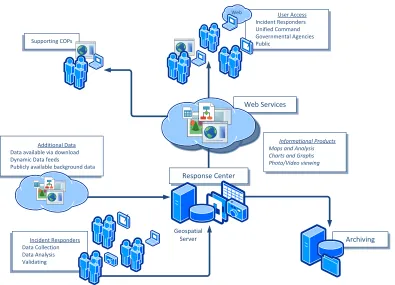
A framework for deploying the COP as a set of enterprise components using a web services-based architecture is shown in Figure 7. Enterprise components for the COP provide an overview of the technical elements used to meet the objectives defined in the earlier sections of this enterprise viewpoint. Details for implementing and deploying these components are provided in the Services Viewpoint (section 4) and the Deployment Viewpoint (section 5).
The Response Center is the focus of the enterprise components – including the geospatial servers that will host the data needed for the users. Data coming from incident responders and additional data sources are ingested into the Response Center servers and quality checked before use in the COP. The COP is provided to connected users and supporting COPs using web services. Web services hosted at the Response Center is routine for medium and large size spills. As technology has progressed, e.g. with cloud hosting, web services have become easier and suitable to implement for all size spills. The Response Center also provides geospatial products for disconnected users. On a periodic basis the Response Center data is archived at a remote location.
COP Information Viewpoint
The COP information landscape
Basic principals
An effective COP is grounded in the following basic principles:
1. The responsible party will manage all data and provide data to government agencies having oversight of response actions as appropriate.
2. All data will be archived and preserved as part of the critical records associated with the incident.
3. Access to incident data will be required for a considerable period of time after the closure of the incident.
4. A central repository of incident data will be created and maintained with the most current information available at any given time.
5. “Snapshots” of incident data are required and will be saved on a weekly basis; they will be available for limited access during the incident and will be preserved afterward. 6. Provenance of all data is to be captured at the time of data entry.
7. COP recommendations are “technology neutral”; users may utilize whatever technology and applications are appropriate.
8. The response effort is organized based on ICS structure and the roles.
Information architecture
The information architecture is predicated on the need for information to be processed, reviewed, and approved prior to being added to the official data store (labeled “Reporting” in the diagram). This process is important because it:
• Allows information release timing to be managed.
• Ensures data quality.
• Allows management to be informed before general release of information.
• Prevents contention between the technical GIS team and end users for system resources.
• Allows data to be processed prior to display thus facilitating integration between datasets.
A typical scenario would have a vendor collecting data associated with an event. At a prearranged interval the vendor would upload their data to the working data store. When data uploading is complete, manual or automated processing is conducted to check data accuracy, replace any obsolete data, and assign any key information to facilitate its
privileges. Access is provided to the data through role-based security established prior to the event (see Section Authentication and authorization services 0). The roles defined by the ICS represent the most complete and common set.
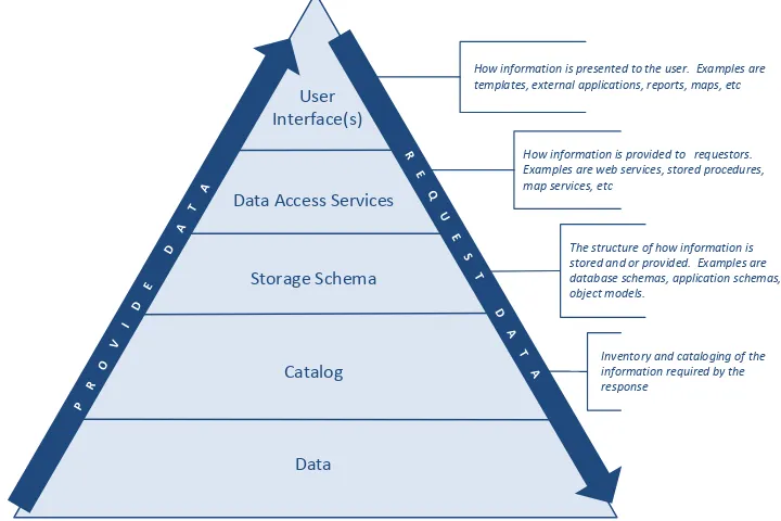
Data access model
Figure 8 shows the model for data insertion and retrieval from the data repository. Typically data flows into the data repository through the top of the pyramid and is accessed the same way. It is expected that each event, vendor, or responsible party will require flexibility in how information is presented or inserted based on their particular tools and processes.
The exception to this assumption is the provision of a set of templates defined for the COP.
See Section 3.5.1 for more information on templates.
Figure 8 Data access model
User interface
Data is presented through a user interface associated with applications purchased or built by the parties associated with the event and/or custom queries or maps created by the teams working the event. Each party may use different applications, maps, or reports, as long as the information specified within the COP is provided. Use of open standards, as specified later in this report, ensures that information can be consumed by different parties and applications, and recognizes the inevitability that in major OSR events, there will almost certainly be more than one COP deployed (refer to Figure 7 – “Supporting COPs”). Data will
be distributed using web services to network-connected users whilst other provisions can be made to deliver data to disconnected users.
Data access can be split into two components:
1) How a user physically connects to a data store. This includes technologies such as Virtual Private Networks (VPN), remote logins, web services, and direct database connections.
2) The objects built to select data from a data store and serve it to the requesting party in a presentation-neutral fashion.
Component 1 is discussed later in this document (section 4) while Component 2 is included in this section.
Each data service should provide a logically complete set of information for the subject of interest. For example, if a data service is created to provide information about employees, the entire employee record should be provided.
By following these rules, referential integrity can be enforced and data validity ensured. A standard set of data services is defined in Annex A but each application or company will no doubt want to enhance this set.
Storage schemas
It is critical that data is stored in the correct storage structure. This is accomplished by the creation of a standard storage schema(s) (also referred to as a data models). Storage schemas are typically documented through an entity-relationship diagram.
Communication, integration and precision are the three key benefits that make a data model important to applications that use and exchange data. A data model is the medium through which project team members from different backgrounds and with different levels of experience can communicate with one another. Precision means that the terms and rules on a data model can be interpreted only one way and are not ambiguous. Integration allows us to view different data together and know that it is logically related or refers to the same common subject.
A data model can be sometimes referred to as a data structure, especially in the context of programming languages. Data models are often complemented by function models, such as in the context of enterprise models.
For the purposes of the COP, the storage schema is best separated into two distinct areas:
1) Geospatial information. See section 3.2 for types of geospatial information. Typically this takes the form of feature classes, shapefiles, coverages, raster files, maps, or other proprietary data storage formats. These are the typical building blocks within a GIS. It is convenient that a GIS simplifies the creation and management of these data objects.
This is an area where careful data analysis and modeling can make or break a system. Unless data is stored in structures that are defined correctly based on the relationships between the data elements and the data type of the elements, storing, retrieving, and linking to data will always be difficult.
Data inventory
The data needed to support an incident response is the key element in a COP. A complete list of data elements is provided in Annex A.
Geospatial information
Geographic or geospatial information is information concerning phenomena implicitly or explicitly associated with a location relative to the Earth (see ISO 19101-19). Geospatial
information is often used as the basis to integrate assessments, situation reports, and incident notification into a COP and as a data fusion and analysis tool to synthesize many kinds and sources of data and imagery10.
Everything about the COP—including the standards used to develop and maintain the system and data, the data that will be gathered and displayed, and how the system will integrate with other systems—depends on first understanding the underlying system. Section 3.3 outlines considerations that should be taken into account when planning and operating an OSR COP.
The information that will be displayed in the COP will come from a variety of sources in a variety of formats. In order to effectively maintain, display, and allow users to interact with the information, careful consideration of the standards that will be used within the COP and how the data will be organized should be a key component of the planning and ongoing maintenance processes. The next sections of this report discusses geospatial information standards and organization.
9
ISO/IS 19101-1:2014 Geographic information - Reference model - Part 1: Fundamentals. See:
http://www.iso.org/iso/iso_catalogue/catalogue_tc/catalogue_detail.htm?csnumber=59164
10 ‘National Incident Management System’, US Department of Homeland Security, December 2008, FEMA
Planning considerations
There are two broad categories of data to consider when determining the data that the system should display. The first is base map or reference data, which includes information about the area and environment that are not specific to the oil spill incident. The categories of reference data that are applicable to many COP implementations are outlined later in this report. The second category of data, also outlined later, is drill and incident specific information that includes information about the spill and the spill response.
The specific standards and data used to develop a COP will be driven by several considerations that include:
• Origin of spill
• Land-based vs. marine
• Arctic vs. temperate, desert or tropical
• Scope / tiered response
• Data access
• Availability of geographic information
• Static vs. real time information
Origin of spill
An oil spill may originate at the wellhead, but it could also originate from a pipeline, infrastructure (such as a refinery or terminal), rail car, or a vessel such as a tanker. Each origin type will require a different approach by the oil spill response team and different geospatial data. Examples include the possibility of a mobile source when a vessel-based spill is encountered.
Land-based vs. marine
COP information requirements must properly account for the unique characteristics of both marine and land-based spills. Simple examples include the need for land status information for terrestrial spills or the need for bathymetric data for marine spills.
Arctic vs. temperate, desert or tropical
Tiered Response
The established three-tiered structure allows those involved in contingency planning to describe how an effective response to any oil spill will be provided; from small operational spillages to a worst-case release at sea or on land. The structure provides a mechanism to identify how individual elements of capability will be cascaded. An organization’s response capability and contingency plan should relate directly to the potential spill scenarios and cover each tier, as appropriate. It is important to note that the tiers are strictly for planning purposes and, in the event of a spill, whatever resources are necessary to adequately respond to the spill must be mobilized regardless of the tier. Planning according to the tiered approach ensures that an appropriate provision of resources is considered for a response of any magnitude as applies to an organization’s risk. It enables responders with access to adequate resources to mobilize an effective and timely initial response using pre-planned strategies and Tier 1 capabilities and to cascade in additional resources as they adapt to any response as it unfolds. Further information can be found in the IPIECA–IOGP ‘Tiered Preparedness and Response’ Good Practice Guide11.
Role based access to data
The organization and security applied to geospatial information within the COP should clearly delineate between information sets that are accessible to the operator and its direct constituents, as opposed to information that may be published for external (public) use.
Access to information is controlled by the role people fill in the response effort. For example, the Incident Commander can view different data than the public. Not only are their data access privileges different, the way they view the same data might be very different. The simplest example is summary views versus detailed views of the same data items.
Availability of geospatial information
The availability of geospatial information may be heavily dependent on the geographical location of an oil spill incident. For example, in North America, a wide array of government, commercial and environmental organizations may provide reference and/or operational information free of charge and without license restrictions. In other locations, it may not be possible to obtain the same wide array of information from such organizations and there will be greater reliance on third party vendor datasets, which will likely have restricted access due to the data licensing terms and conditions. In this case, the Responsible Party or government may need to negotiate alternative license terms with the data suppliers so that the data can be shared with the key users.
11 ‘Tiered Preparedness and Response: Good practice guidelines for using the tiered preparedness and response
Static vs. real-time information
Some of the information provided to the COP will be in real-time. The handling of this dynamic information impacts the design and the use of the COP. For example, should the COP display real-time depths or static depths as referred to on the chart datum on the one hand, and tidal information on the other hand, and both in separate layers? Also, this presents a challenge when archiving and storing data for future use and reference in time. Static information is relative easy to archive, however when consuming a service which shows real time information, such as weather information, there needs to be a method to capture it for future use.
Geospatial information standardization and
organization
Need for geospatial information standards
Consistent standards are important for the use of geospatial information as it has the potential to be misinterpreted, transposed incorrectly, or otherwise misapplied, causing inconspicuous yet serious errors. Standards make it easier for disparate systems utilized during an incident to consume, analyze, display and interact with the information.
Such standards include:
• Coordinate reference system
• Metadata (e.g. ISO 19115)
• Cartographic symbolization
• Scale of use, and accuracy
• Data structure and format
Coordinate Reference System
Maintaining the ‘coordinate integrity’ of all geospatial data ingested, processed and displayed in the COP is vitally important to ensure that all data is displayed in its correct geographical location, both in an absolute and relative sense. For each dataset, it is important to know the Coordinate Reference System (CRS) relevant to the coordinates of the geographical features. For a dataset defined in geographical terms (latitude, longitude), the CRS defines the geodetic datum and reference ellipsoid or spheroid. For a projected (grid) dataset, the CRS will in addition define the map projection and its associated parameters, including units of measure. CRS information is therefore key metadata that needs to be associated with all datasets. Failure to correctly account for the CRS can lead to positioning errors of 100s of meters, or unusable data.
scales they were intended for by setting upper and lower scale limits for each dataset. Beyond these limits, the data will not be displayed or mapped. The COP system
administrators are responsible for assigning such parameters based on their knowledge of the accuracy of the data and its source.
The primary standards for Coordinate Reference Systems applicable to the Oil and Gas industry are those defined by the IOGP Geomatics committee in the EPSG database and associated online registry of global coordinate reference systems.12
IOGP Geomatics guidelines, such as ‘Geodetic awareness guidance note (S&P
01)’ (document ref 373-01),provide a useful reference for those unfamiliar with the topic, and the IOGP’s Geospatial Integrity of Geoscience software (GIGS) guidelines provide methods for testing the integrity of software applications with respect to the correct handling of coordinate information13.
Other useful reference information can be found in the ISO 19111:2007 ‘Geographic information -- Spatial referencing by coordinates’14 and the Open Geospatial Consortium’s
‘Abstract Specification Topic 2 - Spatial referencing by coordinates’15. These OGC and ISO
standards are identical and are aligned with IOGP/EPSG standards.
At a very early stage in an oil spill event, the appropriate CRS for the area shall be chosen and then used as the primary CRS within the GIS system. Any incoming data, which is based on a different CRS, will be transformed before integration into the COP. Accordingly, the availability of software to convert and transform data from different CRS is essential, as is having access to expert advice from a qualified geodesist. The choice of CRS will depend on the geographical extent of the incident, the regulatory environment, and common practice in the area. The EPSG registry16 provides a useful reference of CRS applicable to
specific geographies and countries.
Due to limitations in the technical capabilities of current web mapping technology, there may be constraints in the choice for a projected CRS for the COP map viewer (refer to section 4.2.3). Most current technologies adopt the Pseudo Mercator projection (EPSG Code 3857), which is based on the WGS84 datum (as used by Google Maps, Bing Maps etc.). Such a projection has severe limitations at high latitudes with significant distortion of distances and areas. The COP should warn users of such distortions. For incidents in the Polar Regions, appropriate polar map projections must be used.
Longer term, and when the technology allows, it is recommended to use a General Perspective projection (EPSG Code 9838), such as that used in products like Google Earth
12 IOGP Geomatics website. See: http://info.ogp.org.uk/geomatics/ 13 GIGS guidelines. See: http://publications.ogp.org.uk/?committeeid=476 14
ISO catalogue. See:
http://www.iso.org/iso/home/store/catalogue_tc/catalogue_detail.htm?csnumber=41126&commid=54904 15OGC standards. See: http://portal.opengeospatial.org/files/?artifact_id=39049
and ArcGIS Explorer. The General Perspective projection provides a point of perspective at an infinite (deep space) distance from the earth, providing an acceptable map projection at any location in the world.
For map printing purposes it is recommended to use the projected CRS chosen as applicable to the geographical area of the spill. With reference to section 4.6.2,
recommended practice is to use a standard map template, which will clearly specify the chosen CRS (including the EPSG code).
The above implies that the map projection used for the COP map viewer may be different to that chosen for management of the geospatial data, for spatial analysis or processing, and for hardcopy map purposes. The COP support team must have the resources and expertise to handle the manipulation and quality assurance of the data to avoid any coordinate integrity errors occurring.
Consideration should also be given to the Vertical Datum for any data that refers to topographic heights or bathymetric (water) depths. In general it is recommended to use Mean Sea Level (MSL) (EPSG Code 5100) as the default vertical datum, however when working offshore with published nautical charts, it is likely that such charts will use a different Vertical Datum (usually known as ‘Chart Datum’). This datum is often chosen to be
equivalent to the Lowest Astronomical Tide, and, depending on the tidal regime in the area, could be offset significantly from the Mean Sea Level.
Metadata
Metadata should be captured and added to and maintained as datasets are created and populated. Information should not be considered complete unless it has metadata with it. Where possible, individuals generating the information should be the ones creating the metadata. The very minimum metadata to be captured is the provenance of the data, including:
• Source of the information
• Date of capture
• Contact
• Description of the information
• Any processing done to change the source information
• Any known limitations or issues with the information
• Geographic area of coverage
• Quality of data
Map symbolization
Map or cartographic symbolization should be standardized across the spectrum of the COP, including paper maps, web mapping, and mobile mapping. Any responder should be able to immediately use any and all of the different COP products without having to decipher the information. Where possible and appropriate, the COP should make use of community and international standards, some examples of which include:
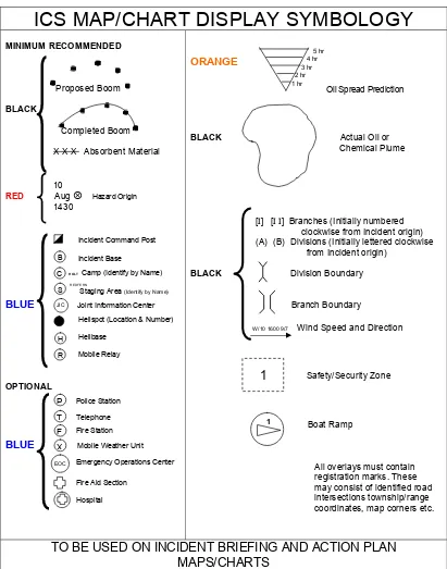
• ICS map symbology as defined by the USCG17 (Figure 9).
• Environmental Sensitivity Index mapping standards from IPIECA-47718 (Figure 10 and
Figure 11).
• The Shell Standard Legend (oil and gas cartographic symbols)19.
• IOGP Seabed Survey Model Symbology standards, which in Version 2 will become closely aligned with the IHO standards20 .
• UK Government- Civil Protection Common Map Symbology21 .
• IHO standards for nautical and hydrographic charts22. The IHO S-100 framework encompasses features such as tides, currents and other categories of nautical information.
Figure 9 provides an example of symbols for use on maps and charts as developed in the ICS community [USCG]. This symbology has some limitations and will be considered for revision in the Data Modeling task of this Recommended Practice.
17 ‘US Coast Guard Incident Management Handbook,’ USCG Commandant Publication P3120.17B, May 2014.
See: http://www.uscg.mil/hq/nsfweb/docs/FinalIMH18AUG2006.pdf
18 ‘Sensitivity Mapping for Oil Spill Response’, July 2012, IOGP Report Number 477. See: http://www.ipieca.org/publication/sensitivity-mapping-oil-spill-response-0
19 Release article. See: http://www.ogp.org.uk/news/2014/shell-releases-its-standard-legend-to-industry-and-academia/
20
IOGP Geomatics website. See: http://info.ogp.org.uk/geomatics/
21 Map symobology. See: https://www.gov.uk/government/publications/emergency-responder-interoperability-common-map-symbols
Figure 9 Map/chart symbology for incident response
Environmental Sensitivity Index (ESI) maps should utilize the standard symbology defined by IPIECA, which is shown in Figure 10.
Figure 10 Symbols for the mapping of sensitive biological resources
Source: IPIECA–IOGP, 2012
A standardized color-coding methodology for shoreline classification should utilize the standard color-coding as defined by IPIECA and presented in Figure 11.
Figure 11 Color code of Environmentally Sensitive Index
Environmental Sensitivity Index (ESI) maps should utilize the standard symbology for relevant socioeconomic sites as defined by IPIECA. A symbol library for socio-economic sites of interest is presented in Figure 12.
Figure 12 Symbols for the mapping of sensitive human use and activities
Source: IPIECA–IOGP, 2012
However the majority of the oil spill-specific standardization does not exist or what does exist was designed long ago and thus does not account for digital mapping systems. It is recommended that a standardized set of map symbolization should be created to support all of the oil spill-specific defined datasets. The symbology should be zoom scale
dependent; at times, depending upon zoom scale, the symbology may need to change. For example a vessel task force may be represented as single point feature when zoomed out but when zoomed in it may show all the vessels that make up the task force. It is thus recommended that oil spill-specific symbology standardization is developed (it is currently planned to be accomplished in a future phase of this project as part of initiatives to create specific OSR data schemas and models). This approach has been successfully used by IOGP in the development specific GIS data models or schemas, an example being those developed for the Seabed Survey Data Model (see reference above).
Scale of use and accuracy
help with visual presentation and organization in an application, but it is important with ensuring accurate data analysis and even system preformation.
The resolution of the data is also a key factor. In an oil spill response environment there is little control over the resolution or scale from third party vendor data unless it has been prior established. It is therefore important information to note and record the scale and resolution of the data when acquiring its from external sources. Polygon layers and data covering wide spatial extents (e.g. oil plumes, oil trajectories, coverage areas) can vary greatly in detail. If the scale and resolution are big and broad, it can result in oversimplification and, if not layered correctly in an application, can hide other layers.
Conversely, the use of detailed data can result in data illegibility if used at higher scales. For example, line and point data that have been collected at fine scales can quickly clutter both map products and web applications. Within oil spill response, this may include features such as boom, dispersant lines, and even the land-water interface for shoreline. In addition, finer detail and a higher resolution can cause the data to render slower, prolonging processing time. To ensure data accuracy and speedy spatial analysis, it is recommended that scale and resolution is noted in the metadata. Data with low resolution overlaid or analyst against high resolution can leave a lot of room for error and/or approximation, running the risk of reducing the data integrity.
A recommended standard is to avoid changing scale by more than two and half times in either direction for data collection and display. However, response data varies in both feature type, size, scale, extent, and display priority. Logical scale dependencies need to be considered for optimal display and labeling when in use by a web application. Only a few key data layers should be displayed at all scales.