UAV PHOTGRAMMETRIC WORKFLOWS: A BEST PRACTICE GUIDELINE
A. Federman a *, M. Santana Quintero a S. Kretz b, J.Gregg b, M. Lengies b, C. Ouimet b, J. Laliberte c
a Department of Civil and Environmental Engineering, Carleton University – 1125 Colonel By Drive, Ottawa, Canada –
[email protected] [email protected]
b Public Services and Procurement Canada- Heritage Conservation Directorate- 30 Victoria Street, Gatineau, Canada –
[email protected] [email protected] [email protected] [email protected]
c Department of Mechanical and Aerospace Engineering, Carleton University, 1125 Colonel By Drive, Ottawa –
Commission II
KEY WORDS: UAVs, Aerial Photogrammetry, Built Heritage Documentation, Prince of Wales Fort
ABSTRACT:
The increasing commercialization of unmanned aerial vehicles (UAVs) has opened the possibility of performing low-cost aerial image acquisition for the documentation of cultural heritage sites through UAV photogrammetry. The flying of UAVs in Canada is regulated through Transport Canada and requires a Special Flight Operations Certificate (SFOC) in order to fly. Various image acquisition techniques have been explored in this review, as well as well software used to register the data. A general workflow procedure has been formulated based off of the literature reviewed. A case study example of using UAV photogrammetry at Prince of Wales Fort is discussed, specifically in relation to the data acquisition and processing. Some gaps in the literature reviewed highlight the need for streamlining the SFOC application process, and incorporating UAVs into cultural heritage documentation courses.
* Corresponding author
1. INTRODUCTION
The unmanned aerial vehicle (UAV) has quite literally taken the cultural heritage field to new heights. UAVs are changing the way we look at the world. They are becoming more of a common tool and are not shrouded in secrecy as they once were. Amazon recently launched a pilot program called Amazon Prime Air, which is a parcel delivery service using UAVs. As UAVs can be equipped with cameras, they are also able to capture aerial photographs and video; a prospect that makes them a very appealing choice as a digital documentation tool.
According to the Canadian Aviation Regulations, the term
‘unmanned aerial vehicle’ is defined as “a power-driven aircraft, other than a model aircraft, that is designed to fly without a human operator on board (Government of Canada-Legislative Services Branch 2017).” UAVs themselves are known by many different names, including remotely piloted vehicles (RPV), drones, and remotely piloted aircraft system (RPAS) (Bolognesi et al., 2015; Nex and Remondino, 2014). The International Civil Aviation Organization (ICAO), of which Canada is a member, uses the term RPAS as their international standard (ICAO 2011). For the context of this review, the term UAV will be used throughout.
To complement the UAV definition, there is also a term called
‘unmanned aerial system’ (UAS). This is used to describe the UAV itself, as well as the ground control station (GCS) (Nex and Remondino, 2014). The GCS is the operator on the ground who is controlling the UAV. This can consist of a formal control room, or an individual operating the system with a handheld remote controller on site.
The practice of using UAVs for photogrammetric applications can be traced back to the 1979 and 1980 tests by Przybilla and Wester-Ebbinghaus on the Schwebebahn (monorail) Wuppertal
(Eisenbeiß 2009; “PHOTOGRAMMETRY ROUND THE
WORLD” 1980; Colomina and Molina 2014). Though, the advent of the specific term ‘UAV photogrammetry’ can be attributed to the work of Henri Eisenbeiss, whose dissertation in 2009 provided new insight into the use of UAVs for aerial photogrammetric applications (Eisenbeiß, 2009). Additionally, the article titled UAV for 3D mapping applications: a review, authored by (Nex and Remondino, 2014), served as an important source of information to understand the state of the arts in this field.
The main goal of this review is to understand how UAV photogrammetry is being used as a low-cost and easy to use tool for the documentation of cultural heritage sites. This review takes on a Canadian context in regards to the legislation governing UAVs, but the overall workflow component can be applied to countries worldwide.
2. UAV HISTORY
In today’s society, UAVs are available for commercial purchase
as they enable the ability to rapidly survey areas and acquire a large amount of data in a short time frame (Lo Brutto et al., 2014)
2.1 UAV Typologies
There are many different ways of classifying UAVs, as they vary depending on a wide range of factors. The Nex and
Remondino article cites UVS International’s three main UAV
categories. UVS International, of which Canada is a member, is an international organization that promotes the non-military use of UAVs, as well as studying rules, regulations, and standards (UVS International, 2016). These categories are:
1. Tactical UAVs (short to medium range, altitude of few hundred meters) (Nex and Remondino, 2014)
2. Strategic UAVs (long endurance, altitude higher than 20,000m) (Nex and Remondino, 2014)
3. Special Task UAVs (combat/decoys systems) (Nex and Remondino, 2014)
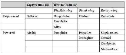
The dissertation of Eisenbeiss provides an alternate way in which UAVs can be classified, which is by being considered as unpowered or powered, as well as lighter than air or heavier than air (Eisenbeiß, 2009). Shown below is a table created by Eisenbeiss to display the various UAV types.
Table 1. Classification of UAVs by Eisenbeiss (Eisenbeiß, 2009)
From the literature explored throughout this review, in relation to variables such as low cost and usability, the most common platform used for aerial photogrammetry are rotary wing aircraft. Specifically, multi-rotors, which include quadcopters, hexacopters, and octocopters, were seen in the articles read (Aicardi et al., 2016; Bolognesi et al., 2015; Bolognesi et al., 2014; Faltýnová et al., 2016; Fiorillo et al., 2013; Hashim et al., 2012; Stek, 2016; Sun and Cao, 2015).
3. CANADIAN UAV REGULATIONS
Though the final acquisition of data is the ultimate goal of using UAVs for photogrammetric purposes, this task should never compromise the safety of the team or public. Therefore, it can be argued that the most important step in the UAV photogrammetric workflow is the due diligence put in by the cultural heritage practitioners in regards to safety procedures when using UAVs. This is in regards to abiding by the legal requirements and legislation for flying UAVs in the countries they are operating in. By understanding the safety procedures and protocols, it helps to minimize the possibility that the UAV will cause damage to both humans on the ground (i.e. the drone takes off on the operator and injures someone) and other aircraft in the sky. For the purposes of this literature review, Canadian UAV legislation will be reviewed.
Transport Canada has a series of protocols to follow when flying UAVs in Canadian airspace, with the most important
regulation being the Special Flight Operations Certificate (SFOC). These regulations are governed by the enabling legislation, the Canadian Aeronautics Act (Government of Canada 2009). The SFOC is the document allowing the use of UAVs for any application other than flying it for fun and pleasure (Government of Canada; Transport Canada; Safety and Security Group 2016a). It helps to ensure that operators will use their UAVs safely. It contains information such as how, when, and where the UAV will be used, maximum flight altitude, the operating area, and safety risk plans (Government of Canada; Transport Canada; Safety and Security Group 2016b).
In order to prepare their own SFOC, cultural heritage practitioners can use the document Staff Instruction No 623-001- Review and Processing of an Application for a Special Flight Operations Certificate for the Operation of an Unmanned Air Vehicle (UAV) system (Government of Canada; Transport Canada; Safety and Security Group 2014), as a guideline. It was published by Transport Canada, and contains the review process for officials to determine if the SFOC should be issued. Specifically, when preparing their own package, specialists should focus on Section 8.0- Reviewing the Application, as they can ‘work backwards’ based off of this
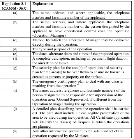
review information in order to ensure that they have all of the information that Transport Canada is looking for. Section 8.0 has been summarized in Table 3.
The SFOC application must be submitted to the specific Transport Canada office in the region that flights are planned.
From the author’s own experience, when dealing with the
Prairie and Northern Region, they do have a set template form to fill out. Though, for the Ontario region, it is up to the individual to prepare their own set SFOC. For the processing of SFOC applications, it is based on a first-come-first-served basis. The Transport Canada website says that they aim to process the applications within a minimum of 20 working days (Government of Canada; Transport Canada; Safety and Security Group 2016b).
This process of 20 working days can be a hindrance to projects with tight timelines and/or budget constraints. Sometimes due to the severity of the project (i.e. UAV used for surveillance of collapsed buildings and/or photogrammetric models of existing conditions), this timeline is not feasible and possible for the practitioner. Therefore, it is suggested that Transport Canada create some form of fast-track process, specifically when dealing with projects on National Historic Sites commissioned by the Heritage Conservation Directorate.
Regulation 8.1 623.65(d)(3)(X)
Explanation
(a) The name, address, and where applicable, the telephone number and facsimile number of the applicant.
(b) The name, address, and where applicable the telephone number and facsimile number of the person designated by the applicant to have operational control over the operation (Operation Manager).
(c) Method by which the Operation Manager may be contacted directly during the operation.
(d) The type and purpose of the operation.
(e) The dates, alternate dates and times of the proposed operation. (f) A complete description, including all pertinent flight data on
the aircraft to be flown.
(g) The security plan for the area(s) of operation and security plan for the area(s) to be over flown to ensure no hazard is created to persons or property on the surface.
(h) The emergency contingency plan to deal with any disaster resulting from the operation."
(i) The name, address, telephone and facsimile numbers of the person designated to be responsible for supervision of the operation area (Ground Supervisor), if different from the Operation Manager during the operation.
(j) A detailed plan describing how the operation shall be carried out. The plan shall include a clear, legible presentation of the area to be used during the operation. All Certificate applicants will identify the class(s) of airspace in which the operations are planned.
(k) Any other information pertinent to the safe conduct of the operation requested by the Minister.
Table 2. Contents to be included in a SFOC (Adapted from (Government of Canada; Transport Canada; Safety and Security
Group 2014))
One last note of importance- if cultural heritage specialists do not abide by the laws set out by Transport Canada regarding the use of UAVs, the consequences can be fines up to $25,000 and/or jail time (Government of Canada; Transport Canada; Safety and Security Group 2016a).
4. UAV PHOTOGRAMMETRY AND CULTURAL HERITAGE DOCUMENTATION
The 2009 dissertation by Eisenbeiss can be considered as one of the first major work in regards to using UAVs for cultural heritage purposes (Eisenbeiß, 2009). Since that time, the popularity of using the platform of UAVs for documentation through UAV photogrammetry, has only increased due to technological advances and the ease at which UAVs can be purchased.
From the literature explored, UAVs have been primarily used for one of two main applications. These involved: complimenting the initial survey by capturing inaccessible roof areas or facades over 4 floors (Faltýnová et al., 2016), or using the UAV to complete the survey in its entirety (Aicardi et al., 2016; Bolognesi et al., 2015; Xu et al., 2016).
UAV photogrammetry is described as “a photogrammetric measurement platform, which operates remotely controlled, semi-autonomously, or autonomously, without a pilot sitting in the vehicle (Eisenbeiß, 2009).” The workflow shown below is presented by Nex and Remondino (Nex and Remondino, 2014) as a basis for UAV image processing. It is important to note that a separate category can be attached to mission planning that contains all of the safety formalities and applications discussed earlier (i.e. SFOC). Additional information such as completing a Flight Log after each flight can also go in this category. The basic flight logbook contains providence information about the flight (i.e. flight pattern, time of flight, battery life, wind speeds, temperature, etc.). Websites such as Airdata UAV (“Airdata UAV - Flight Data Analysis for Drones” 2017) are able to track the metadata contained in UAV memory cards.
Figure 3: UAV Acquisition Workflow (Nex and Remondino, 2014)
4.1 Comparison of UAVs
Though there are many UAVs available for commercial purchase, some have exhibited more success for UAV photogrammetric applications than others. Almost all of the articles explored used a rotary wing system, which is the type of UAV that will be presented here for a brief comparison. A common theme throughout the articles was the goal of low cost data acquisition. After reviewing the cost of the UAVs used in some of the test flights (Bolognesi et al. 2015, 2014; Sun and Cao 2015) the average was around $2000 USD, which can be used as a benchmark figure to compare future UAV tests. Some common UAVs at that price point or lower include the DJI Phantom 4 and 4 Pro, 3DR Solo, and Yuneec Typhoon (myfirstdrone.com 2017).
Another way to classify potential UAVs for photogrammetric uses is if they come with a built in camera feature. Those that do come with one are limited in regards to their focal length and sensor size, and therefore the UAV must be flown closer to the object of interest in order to ensure the same photograph resolution as a camera with a larger sensor. The positive attribute is that they are a complete system and do not require the purchase of extra features (camera and gimbal). Additionally, the camera can be oriented at a variety of angles for oblique images.
UAVs that do not have a built in camera require additional steps before they become operational for photogrammetry (i.e. the addition and attachment of a camera and gimbal system). The positive attributes of this type of system is that they are able to capture higher quality images during each flight test because of the addition of DSLR cameras.
4.2 GSD (Ground Sample Distance) Calculation
GSD is determined in order to understand the size of one pixel on the image, and how that corresponds to a set measurement on the object we are surveying. GSD is expressed in mm, or cm. For example, if the required GSD is 5mm, which means that 1 pixel on the camera image corresponds to 5mm on the object. The formula used for calculating GSD is shown below:
(1)
Calculating GSD for UAV flights varies slightly as compared to calculating it for capturing vertical facades. It is important to set the Distance to the object variable as the farthest point away from the camera that you want to survey, instead of the object
GSD = �� �
� ℎ ℎ = 1− � %
100 �
closest to the camera. By doing so, you are ensuring that the point farthest away from your sensor will still have sufficient resolution for digital reconstruction purposes. If you set your GSD at the closest object, then details of the farther object will not be displayed with the same accuracy.
Formulas (2) and (3) explain how to calculate the overlap between two camera positions, which helps to ensure a sufficient photocover:
(2)
(3)
4.3 Flight Types/Patterns
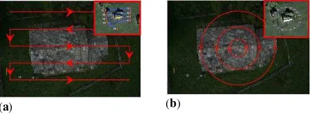
According to Nex and Remondino (Nex and Remondino, 2014), three primary flight modes have been identified. These are manual, assisted, or autonomous (Nex and Remondino, 2014). Examples of typical image acquisition overlay are shown in Figure 5.
Figure 4: Different flight Patterns: a) manual mode, b) low-cost navigation system with irregular image overlap, and c) automated flying and acquisition mode (Nex and Remondino,
2014)
Option b is not usually performed, as flights are done either by manual acquisition (a) or full automation (including take-off and landing) (c). UAVs with built in cameras make the manual acquisition very easy, as the user is able to see the view of the UAV through a corresponding tablet and then take their pictures accordingly. Automatic image acquisition can be done through software such as the Pix4D app, but is only useful for nadir images as the camera angle is not changed by the software. Additionally, flights are usually done in linear or circular patterns to capture information to ensure consistent overlap (Aicardi et al., 2016).
(a) (b)
Figure 5: Flight Path Shapes (a) Linear Pattern (b) Circular Pattern
4.4 Ground Control Point (GCP) Acquisition
A complimentary step to the image acquisition process is the taking of ground control points (GCPs) on site. This is done though a traditional surveying method of using a total station. These control points are then captured in the photographs taken
by the UAV in order to properly align and scale the object of interest for digital reconstruction during post processing.
Since UAVs are equipped with Global Navigation Satellite Systems (GNSS) technology, another option that exists is to combine the photographs solely using that information. The author is currently exploring this methodology as a part of his research. This involves registering the photos in photogrammetric software packages based solely off of the GPS coordinates that are logged as part of the exif data from each photograph. Unfortunately this does not scale the image as accurately as using GCPs due to relatively low accuracy of the GPS system inside the UAV as compared to those in normal airplanes.
4.5 Camera Orientation
From the literature explored, there are two types of camera orientations when capturing aerial photographs. These are nadir (camera positioned vertically) and oblique (camera positioned on an angle). At first, UAV photogrammetry was used mostly with nadir images for the creation of Digital Terrain (or Surface) Models (Aicardi et al., 2016). This was because there was not enough information with these nadir images to successfully capture details of facades. That is why oblique images are becoming more important in the UAV photogrammetric process. Especially for systems with built in cameras, oblique images are easy to capture because it only involves adjusting the camera to the desired angle using the remote control. Or, if the camera is not built in, it can be adjusted before each flight. Using oblique images is shown in (Aicardi et al., 2016; Ostrowski, 2016; Vetrivel et al., 2015).
4.6 Data Processing
The processing of UAV acquired photographs is done using the traditional photogrammetric software packages. A comparison of the software is shown in the following section, as explained in one of the articles reviewed. Though, the guiding question behind acquiring data is how it can be integrated and registered with information collected by terrestrial documentation techniques (terrestrial photogrammetry and laser scanning). The process here is that point clouds were created through either 3D laser scanning or terrestrial photogrammetry to use as a comparison to the point cloud created by UAV photogrammetry. This concept was explored in numerous articles consulted (Aicardi et al., 2016; Aicardi et al., 2016; Bolognesi et al., 2015; Bolognesi et al., 2014; Hashim et al., 2012) and the general conclusion made was that the UAV point cloud model was comparable in accuracy.
4.7 Software Comparison
The most common software used to process the images based off of the literature explored was Agisoft PhotoScan. Though, one article published by Aicardi et al. in 2016 (Aicardi et al. 2016) did an interesting test where they compared the results of different photogrammetric software packages. This type of comparison is very beneficial to see which software is able to best handle oblique UAV images in regards to the point density of the created model for visualization and further modelling purposes. That group used 190 images, taken by a Sony ILCE-5100 camera (Aicardi et al., 2016). Figure 7 below is a summary chart of the number of millions of points created using each respective software. A high quality setting in each was used to come up with the final results.
�=�
Figure 6: Comparison of dense point cloud number of points- Agisoft Photoscan Professional (PS), Pix4D, 3Df Zephyr (3DZ), SURE, MicMac (MM), VisualSFM (VSFM), and
ContextCapture (CC) (Aicardi et al., 2016)
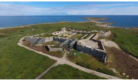
5. PRINCE OF WALES FORT CASE STUDY 5.1 History and Significance
Prince of Wales Fort is located in Churchill, Manitoba, at the mouth of the Churchill River. The site falls within the Prairie and Northern Region of Transport Canada. Due to the built-up infrastructure across the river and less than nine kilometres away, the SFOC exemption did not apply. Therefore, a SFOC application was required so this project could take place.
The site itself was constructed over a forty year period from 1731-1771 by the Hudson’s Bay Company in order to protect their northern trade routes (Hucker and Canadian National Historic Sites Directorate, 1994). It was damaged by the French in 1782, and was left dormant and neglected for 150 years until conservation initiatives were put forth by the Historic Sites and Monuments Board of Canada (Hucker and Canadian National Historic Sites Directorate, 1994). The conservation efforts of
the 1930’s and 50’s focused on the stabilization of the exterior rampart walls, as some sections were in danger of collapse (Hucker and Canadian National Historic Sites Directorate, 1994). As the site was open to the public, safety of the site was an imminent priority as to not put any visitors at risk of injury. Though the initial interventions did indeed help to ensure the continued longevity of the site, the repair techniques used negatively impacted aspects of the site’s authenticity. Specifically, cement was poured behind the walls as a consolidation technique, which today is seen as a very intrusive intervention (Hucker and Canadian National Historic Sites Directorate, 1994). This erased any signs of 18th century craftsmanship in the specific areas that were commissioned for repair (Hucker and Canadian National Historic Sites Directorate, 1994). The site has been greatly affected in recent years due to climate change. Visible cracks and masonry deterioration are visible on site, and monitoring programs have been put in place in order to keep a detailed record of any changes.
5.2 Purpose of Project/Site Restrictions
The overall goal of the project was to test the capabilities of commercially available UAVs for the creation of an accurate photogrammetric model of the site that could be used for the creation of orthophotos for condition assessment purposes through as-built drawings, and possibly crack monitoring/identification. Flights were conducted over the course of three days: August 9-11, 2016.
Figure 7: Location of Prince of Wales Fort (“Google Maps” 2017)
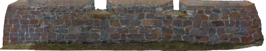
Figure 8: Prince of Wales Fort (taken by Alex Federman)
In regards to restrictions on site, the most important factor was that the weather dictated working patterns. If the winds were greater than 32 km/h, then flights could not be conducted. Additionally, if there was any sign of rain, flying could not commence. During our time on site, the wind speeds were approximately 20km/h, and there were only a few instances of rain, which unfortunately shut down the operation for a few hours.
As we were flying underneath a flight path, this presented another restriction when trying to capture overall site context images at high altitudes. Any time other aerial vehicles were spotted, the UAV was brought back to the operator as an extra safety precaution. Additionally, the safety mode was turned on, which meant that the maximum altitude of the UAV was 30 m AGL (above ground level). This would help to ensure that the
UAV would be within the operator’s line of sight at all times.
5.3 Equipment Used
5.4 Data Collection
Ten rounds of flights were conducted when on site, all with varying purposes. The flights were done through manual piloting by Alex Federman and all images captured were also done manually. The general flight path followed was of the linear nature.
Flight 1 was a general test of nadir images, while Flights 2 and 3 were nadir images at 15m. Flight 4 was nadir images at approximately 25m altitude for more contextual images around the perimeter of the fort.
Flight 5 was primarily video footage of the fort, while flights 6-9 were oblique images of the fort. Images from flights 6-6-9 were used for the creation of the final photogrammetric model, as we wanted to test how well the oblique images would be processed and aligned, and they types of results they would give. The relative altitudes of images acquired of the exterior walls ranged from 8m to 20m. The interior courtyard images were acquired at heights ranging from 8-15m. Finally, Flight 10 was a test of capturing images when the UAV was positioned at 3-4m away from the wall and aligning the camera perpendicular to the wall.
5.5 Data Processing
The images were first manually inspected and checked to ensure they were not blurry and would be useful in the creation of a photogrammetric model. The image quality was then checked using Agisoft PhotoScan, and any that were below 75% were deleted. A total of 767 pictures were used. 161 control points were used to help scale the model.
Photos were then masked to reduce the amount of residual noise, i.e. points from the sky, on the final model. Because of
the Phantom’s very large field of view, it resulted in a large
amount of overlap between the images, which helped with the image alignment process. The drawback to this is that images focusing on the exterior walls also included some parts of the inner courtyard. Therefore, masking helped to solve this problem. Ground control points (GCPs) were added to the PhotoScan model before image alignment in order to help with aligning interior and exterior images, as well as providing scale to the model. These GCPs were surveyed by John Gregg and Shawn Kretz for their own terrestrial photogrammetric survey of the Fort. A dense cloud was then created in PhotoScan at a high setting.
The cumulative relative error of the model calculated by the Photoscan software is approximately 10mm. This error on the dense cloud model is sufficient for the creation of a drawing set at a scale of 1:50.
Unfortunately, generating a mesh model from PhotoScan was unsuccessful, as the software kept crashing due to the constraints from the computer hardware, as 32GB of RAM was not enough to process the mesh. Therefore, an alternative strategy was used, whereby the images were imported into ContextCapture. The benefit of using ContextCapture is that for mesh and dense cloud processing, it is RAM dependent. A specific amount of RAM can be allotted for the generation of meshes or dense cloud models by separating the model into a series of individual tiles instead of one whole model like is done in PhotoScan. Additionally, the camera parameters from PhotoScan were also imported into ContextCapture as an Omega Phi Kappa text file to aid in the Aerotriangulation step for registering the photographs. This way, the GCPs did not have to be reselected again in ContextCapture.
The next step in the workflow was the creation of a mesh in Wavefront .obj format. The final product resulted in 16 individual tiles. As only one tile can be imported back into PhotoScan at a time per individual chunk, the tiles had to be merged. CloudCompare was the software used to merge the tiles into one whole model. This new .obj file was then imported back into the PhotoScan chunk, which aligned in the same coordinate system as the dense cloud model because of the fact that the same camera parameters were used in the ContextCapture model generation.
From here, a series of orthophotos were created for individual wall sections of interest. The importance of adding the mesh back into the PhotoScan file was because of the usability of PhotoScan for orthophoto generation. The orthophotos had an approximate resolution of 5mm per pixel. Though that result is higher than the 3mm value for a 1:50 scale noted by Historic England’s Metric Survey Specifications for Cultural Heritage, from visual inspection of the image, the mortar joints and individual stones were all clearly visible to be traced for an elevation drawing (Andrews, Bedford, and Bryan 2015). Figure 9 shows the generated orthophoto for wall section O-P.
5.6 Lessons Learned
This endeavour allowed the authors to gain valuable experience with both acquiring aerial images, as well as processing data collected through aerial imagery.
A new methodology should be tried the next time UAVs are used for aerial photogrammetry applications, as the 5mm per pixel resolution, though acceptable for a 1:50 elevation drawing set, was too high for a crack monitoring program. Therefore, the new strategy employed should be similar to that of the Flight 10 test, whereby the camera is oriented at 90 degrees towards the object like in terrestrial photogrammetry. The pilot should then
perform a vertical linear pattern over the face of each wall, changing the camera positioning to an oblique angle at the top of the walls to capture the top details. Additionally, a UAV with a larger sensor size, or one that is equipped with a DSLR can be used for image acquisition. This would hopefully result in the sub-millimetre resolution required for more detailed crack monitoring procedures.
For equipment, three batteries and two chargers would be the optimal number for future aerial photogrammetry projects. This would ensure that 60+ minutes of continuous flight time could occur, helping to speed up the data capturing would process. This was because there were periods of time on site where no work could be done because the batteries were still charging, thereby slowing down the data capturing process.
Overall, aerial photogrammetry proved to be advantageous because the terrain could also be captured and properly aligned into the model. This helps to show the site in its surroundings environment, which is one of the character defining elements of the Prince of Wales Fort site.
6. GAPS IN CURRENT LITERATURE
There were two predominant gaps identified in the literature reviewed. The first has to do with the need for expanded education in regards to UAVs, whereas the second is in relation to the SFOC process.
In the article, Integrating UAVs into Geomatics Curriculum
(Al-Tahir, 2015), it is argued that as UAVs are becoming more available for commercial purchase, there is a lack of formal training courses to be able to use them correctly. Al-Tahir (Al-Tahir, 2015) proposes three alternatives in his article:
A Design project- This can be similar to the Capstone that Carleton University does during the fourth year of engineering undergraduate degrees.
A short module within a larger course- This can be a few lectures in specific courses about cultural heritage documentation, such as Historic Site Recording, taught by Mario Santana at Carleton University, and/or Directed Reading taught by Christian Ouimet at Carleton University.
A Complete advanced course in UAV photogrammetry including detailed photogrammetric processing and hands on training.
The whole endeavour is based on equipment in regards to the funds available to purchase both hardware and software components. This course/module can use off the shelf UAVs or those that are modular and can be customized.
The SFOC process is one that should also be modified. Cultural heritage practitioners, ideally those working for the Federal Government, should speak with Transport Canada about creating a process to streamline the SFOC application for their work. 20 working days for processing is much too long for a project with tight timeframes.
Additionally, Transport Canada should consider creating a uniform SFOC template for all of their respective regions to follow. These can be separate forms for both lower cost and weight UAVs (less than 1kg), as well as those that weigh more than 1kg. This could also help to speed up the processing for
these applications since all forms will be of the same nature, making it easier for Transport Canada officials to process.
7. CONCLUSION
It can be concluded that UAVs offer another platform for image acquisition for photogrammetric purposes. As the field of UAV documentation has grown exponentially since the dissertation of Eisenbeiss (Eisenbeiß, 2009), there is a need for continuing research about best practice guidelines and methodologies. In particular, cultural heritage specialists wanting to use UAVs in Canada should pay particular attention to the proper process of securing the SFOC application. Without this document, flights are not permitted, and the documentation cannot begin to take place. Additionally, parameters such as GSD, flight paths and patterns, and camera orientation, should be carefully planned out beforehand to minimize wasted time when on site. This was evident in the Prince of Wales documentation project, whereby one strategy of image capture- oblique, did not give detailed enough results for the development of a crack monitoring program. It did give adequate results for the creation of both a plan and elevation drawing set. In regards to data processing, a combination approach of using PhotoScan for initial image alignment and dense cloud processing, and then ContextCapture for mesh generation, proved to be a successful workflow based on the quality of the orthophotos produced.
8. REFERENCES
Aicardi, I., F. Chiabrando, N. Grasso, A. M. Lingua, F. Noardo,
and A. Spanò. 2016. “UAV Photogrammetry with Oblique
Images: First Analysis on Data Acquisition and Processing.” ISPRS - International Archives of the Photogrammetry, Remote Sensing and Spatial Information Sciences XLI-B1 (June): 835– 42.
“Airdata UAV - Flight Data Analysis for Drones.” 2017. Accessed April 14, 2017. https://airdata.com/.
Al-Tahir, R. 2015. “Integrating UAV into Geomatics
Curriculum.” In ISPRS - International Archives of the Photogrammetry, Remote Sensing and Spatial Information Sciences, XL-1-W4:387–90. Copernicus GmbH.
Andrews, David, Jon Bedford, and Paul Bryan. 2015. Metric Survey Specifications for Cultural Heritage. Historic England.
Bolognesi, M., A. Furini, V. Russo, A. Pellegrinelli, and P.
Russo. 2014. “Accuracy of Cultural Heritage 3D Models by
RPAS and Terrestrial Photogrammetry.” In ISPRS -
International Archives of the Photogrammetry, Remote Sensing and Spatial Information Sciences, XL-5:113–19. Copernicus GmbH.
Bolognesi, M., A. Furini, V. Russo, A. Pellegrinelli, and P. Russo. 2015. “Testing the Low-Cost RPAS Potential in 3D Cultural Heritage Reconstruction.” In ISPRS - International Archives of the Photogrammetry, Remote Sensing and Spatial Information Sciences, XL-5-W4:229–35. Copernicus GmbH.
Colomina, I., and P. Molina. 2014. “Unmanned Aerial Systems
Eisenbeiß, Henri. 2009. UAV Photogrammetry. ETH Zurich, Switzerland.
Faltýnová, M., E. Matoušková, J. Šedina, and K. Pavelka. 2016.
“Building Façade Documentation using Laser Scanning and Photogrammetry and Data Implementation into BIM.” In ISPRS
- International Archives of the Photogrammetry, Remote Sensing and Spatial Information Sciences, XLI-B3:215–20. Copernicus GmbH.
Fiorillo, Fausta, Belén Jiménez Fernández-Palacios, Fabio
Remondino, and Salvatore Barba. 2013. “3d Surveying and Modelling of the Archaeological Area of Paestum, Italy.”
Virtual Archaeology Review 4 (8): 55–60.
“Google Maps.” 2017. Google Maps (Prince of Wales Fort).
Accessed February 13.
https://www.google.ca/maps/place/Prince+of+Wales+Fort+Nati
onal+Historic+Site/@58.7642573,-94.1491927,12.22z/data=!4m5!3m4!1s0x526fd936220be4fd:0x b50ac3f136caa09b!8m2!3d58.797175!4d-94.213122.
Government of Canada-Legislative Services Branch. 2017.
“Consolidated Federal Laws of Canada, Canadian Aviation
Regulations.” February 9.
http://laws- lois.justice.gc.ca/eng/regulations/SOR-96-433/FullText.html#h-779.
Government of Canada, Transport Canada. 2009. “Aeronautics
Act (R.S., 1985, C. A-2).” October 15. http://www.tc.gc.ca/eng/acts-regulations/acts-1985ca-2.htm.
Government of Canada, Transport Canada. 2016a. “Exemption from Paragraph 571.08(1)(b) of the Canadian Aviation
Regulations.” December 21.
http://www.tc.gc.ca/civilaviation/regserv/affairs/exemptions/doc s/en/2880.htm.
Government of Canada, Transport Canada. 2016b. “Exemption from Paragraph 571.08(1)(b) of the Canadian Aviation
Regulations.” December 21.
http://www.tc.gc.ca/civilaviation/regserv/affairs/exemptions/doc s/en/2879.htm.
Government of Canada; Transport Canada; Safety and Security
Group, Civil Aviation. 2014. “Staff Instruction (SI) No. 623
-001.” December 22.
http://www.tc.gc.ca/eng/civilaviation/standards/general-recavi-uav-4161.html#toc8_0.
Government of Canada; Transport Canada; Safety and Security
Group, Civil Aviation. 2016a. “Flying Your Drone Safely and
Legally.” June 7, 2016.
http://www.tc.gc.ca/eng/civilaviation/opssvs/flying-drone-safely-legally.html.
Government of Canada; Transport Canada; Safety and Security
Group, Civil Aviation. 2016b. “Getting Permission to Fly Your
Drone.” June 7.
https://www.tc.gc.ca/eng/civilaviation/opssvs/getting-permission-fly-drone.html.
Hashim, K. A., A. Ahmad, A. M. Samad, K. NizamTahar, and
W. S. Udin. 2012. “Integration of Low Altitude Aerial & Terrestrial Photogrammetry Data in 3D Heritage Building
Modeling.” In 2012 IEEE Control and System Graduate
Research Colloquium, 225–30.
Hucker, Jacqueline, and Canadian National Historic Sites
Directorate. 1994. “Prince of Wales Fort: A History, Documentation and Analysis of the 20th Century Repairs to the
Outer Walls.”
ICAO. 2011. “ICAO Circular 328, Unmanned Aircraft Systems
(UAS). Technical Report. International Civil Aviation
Authority.” Montreal, Canada.
Lo Brutto, M., A. Garraffa, and P. Meli. 2014. “UAV Platforms
for Cultural Heritage Survey: First Results.” In ISPRS Annals
of Photogrammetry, Remote Sensing and Spatial Information Sciences, II-5:227–34. Copernicus GmbH.
myfirstdrone.com. 2017. “May 2017 Top 20 Best Drones For
Sale List | MyFirstDrone.” My First Drone. Accessed May 1, 2017. https://myfirstdrone.com/tutorials/buying-guides/best-drones-for-sale/.
Nex, Francesco, and Fabio Remondino. 2014. “UAV for 3D Mapping Applications: A Review.” Applied Geomatics 6 (1): 1–15.
Ostrowski, W. 2016. “Accuracy of Measurements in Oblique
Aerial Images for Urban Environment.” In ISPRS -
International Archives of the Photogrammetry, Remote Sensing and Spatial Information Sciences, XLII-2-W2:79–85. Copernicus GmbH.
“Photogrammetry Round the World.” 1980. The Photogrammetric Record 10 (55): 107–12.
Stek, Tesse D. 2016. “Drones over Mediterranean Landscapes. The Potential of Small UAV’s (Drones) for Site Detection and
Heritage Management in Archaeological Survey Projects: A Case Study from Le Pianelle in the Tappino Valley, Molise
(Italy).” Journal of Cultural Heritage 22 (November): 1066–71.
Sun, Z., and Y. K. Cao. 2015. “Data Processing Workflows
from Low-Cost Digital Survey to Various Applications: Three Case Studies of Chinese Historic Architecture.” In ISPRS - International Archives of the Photogrammetry, Remote Sensing and Spatial Information Sciences, XL-5-W7:409–16. Copernicus GmbH.
UVS International. 2016. “Who We Are and What We Do – UVS International.” Accessed December 18, 2016. http://uvs-international.org/about/who-we-are-and-what-we-do/.
Vetrivel, Anand, Markus Gerke, Norman Kerle, and George
Vosselman. 2015. “Identification of Damage in Buildings
Based on Gaps in 3D Point Clouds from Very High Resolution
Oblique Airborne Images.” ISPRS Journal of Photogrammetry
and Remote Sensing 105 (July): 61–78.
Xu, Z., T. H. Wu, Y. Shen, and L. Wu. 2016. “Three
Dimentional Reconstruction of Large Cultural Heritage Objects