COLLISION VISUALIZATION OF A LASER-SCANNED POINT CLOUD OF
STREETS AND A FESTIVAL FLOAT MODEL USED FOR THE REVIVAL OF
A TRADITIONAL PROCESSION ROUTE
Weite LI a, Kenya SHIGETA a, Kyoko HASEGAWA a, Liang LI a, Keiji YANO b, Satoshi TANAKA a
a
College of Information Science and Engineering, Ritsumeikan University, Kusatsu, Shiga 525-8577, Japan - (stanaka, hasegawa)@media.ritsumei.ac.jp
b
Department of Geography, Ritsumeikan University, Kita-ku, Kyoto 603-8577, Japan
Commission II, WG II/3, WG II/4
KEYWORDS: Laser-scanned Point Cloud, Cultural Heritage, Collision Visualization, Collision, Stochastic Collision Search
ABSTRACT:
Recently, laser-scanning technology, especially mobile mapping systems (MMSs), has been applied to measure 3D urban scenes. Thus, it has become possible to simulate a traditional cultural event in a virtual space constructed using measured point clouds. In this paper, we take the festival float procession in the Gion Festival that has a long history in Kyoto City, Japan. The city government plans to revive the original procession route that is narrow and not used at present. For the revival, it is important to know whether a festival float collides with houses, billboards, electric wires or other objects along the original route. Therefore, in this paper, we propose a method for visualizing the collisions of point cloud objects. The advantageous features of our method are (1) a see-through visualization with a correct depth feel that is helpful to robustly determine the collision areas, (2) the ability to visualize areas of high collision risk as well as real collision areas, and (3) the ability to highlight target visualized areas by increasing the point densities there.
1. INTRODUCTION
The recent development of laser-scanning technology has enabled the capture of three-dimensional (3D) shapes of real objects quickly and precisely. So far, the application of the technology to cultural heritage objects has been mainly to record their static 3D shapes (Ioannides et al., 2014). The technology, however, should also be useful for analysing the dynamical behaviour of 3D cultural heritage objects. In fact, in industrial fields, laser-scanned data are often used for collision detection simulation in the facility location of plants (Niwa et al., 2015). We contend that such collision detection simulation is also useful for preserving and analysing intangible cultural heritage such as traditional festivals.
In this paper, we propose a method for visualizing the collisions of point cloud objects and apply it to analyse a simulation of the collision between a parading festival float and the street. More concretely, we apply our proposed visualization method to the collision detection simulation for the route revival of the famous festival float Ofune-hoko in the Gion Festival, which is held Then, the collision of the street and the float is investigated and visualized by our method.
Several methods have been proposed for the collision detection of point clouds. There are methods to subdivide a 3D space into small cells by means of the octree or the kd-tree (Figueiredo et al., 2010, Hermann et al., 2014, Klein et al., 2004, Pan et al., 2013a, Shauer et al., 2014). This type of method is suitable for precise collision detection. There are also screen space methods that are suitable for quick collision detection (dos Anjos et al., 2012, Radwan et al., 2014, Niwa et al., 2016).
Probabilistic collision detection between noisy point clouds is also proposed (Pan et al., 2016). Our proposed collision visualization is applicable to any type of collision detection method. In the current work, we adopt the method based on the kd-tree.
Thus far, research on the point-based collision detection of laser-scanned data has not been much related to research on visualization. In this paper, we propose a visualization method suitable for the detection of collisions of point clouds. The characteristic features of our visualization are (1) a see-through visualization with a correct depth feel that is helpful to robustly identify the collision areas, (2) the ability to visualize areas of high collision risk as well as real collision areas, and (3) the ability to highlight real collision areas and areas of high collision risk by increasing the point densities there. For (1), we utilize the stochastic point-based transparent rendering proposed recently (Tanaka et al., 2016). Based on the high-quality see-through views realized by the rendering, we propose how to highlight collision areas and high collision risk areas effectively by (2) and (3). In our proposed see-through visualization, preciseness can be achieved by efficiently using the redundancy of the point data. Thus, we haven’t carried out point cloud demonstrate our method by applying it to collision visualization of the culturally important festival float. Section 5 presents the conclusion.
The Gion Festival is one of the most famous festivals in Japan. Its origin dates to the year 869, when it was instituted as a religious ceremony to appease the gods during the outbreak of an epidemic. The festival occurs annually in Kyoto City and spans the entire month of July. The highlight of the festival is
the Yama-Hoko float procession, which consists of parades of
beautifully decorated festival floats in mid-July. The Yama-Hoko floats are portable shrines, in which the go-shintai, the physical objects in which the gods reside, have been installed. The Yama-Hoko float procession that accompanies the opening of the festival is called the sakimatsuri, and the return procession is called the atomatsuri. The boat-shaped Ofune-hoko float (see Figure 1), on which we focus in this paper, is an important Yama-Hoko float that performs the role of the final position in the atomatsuri procession every year.
Figure 1. The Ofune-hoko float in the Gion Festival (2014).
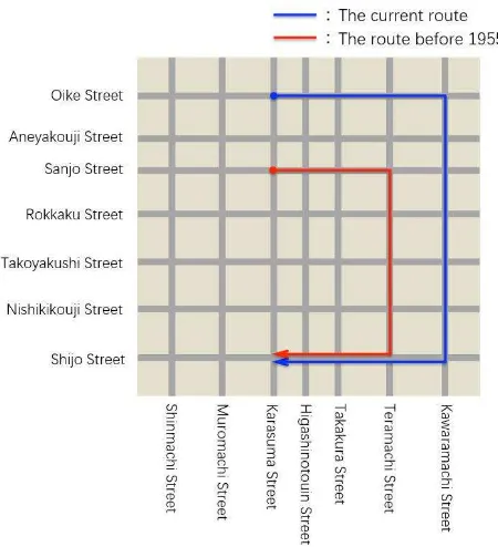
During the period of Japan’s rapid economic growth after the Second World War, the government wanted to help foster and administer tourism more effectively and to relieve traffic congestion in the age of the automobiles. In 1956, the route of the sakimatsuri procession was first changed. In this period, the route of the atomatsuri procession continued along its traditional path, but in 1966, it was combined with the sakimatsuri procession, and on July 17, the atomatsuri procession followed the sakimatsuri procession. This is how things have been up until the year 2013. After almost half a century, the traditional atomatsuri procession was revived in the year 2014. However,
Sanjo Street and Teramachi Street, which were once used as
parts of the original procession route, are not included in the procession path of the resurrected atomatsuri (see Figure 2), although the Kyoto City government hopes to revive the whole original route. The reason why the original route has not been revived is that we do not know whether the Ofune-hoko float is still capable of cruising these streets. In fact, we do not know whether the Ofune-hoko float can go through the streets without collision due to major changes in the road conditions such as newly built houses, electric wires, and signboards.
Therefore, we execute a computer simulation for detecting collisions between the Ofune-hoko float and the original procession route in a virtual space that is constructed with laser-scanned point clouds. To support this collision detection simulation, we develop a collision visualization method that is explained below. The point clouds for the streets are acquired by a mobile mapping system (MMS), and the point cloud of the Ofune-hoko float is created by sampling a polygon model that is precisely constructed with CAD software.
Figure 2. The current route and the original route of the atomatsuri procession of the festival floats in the Gion Festival.
3. PROPOSED METHOD
In this section, we explain our collision visualization method. The method consists of two steps: (1) the assignment of colour and opacity to points and (2) the execution of stochastic point-based transparent rendering. Below, we explain each step.
3.1 Assignment of Colour and Opacity to Points
The colour and opacity of each point in the two given point clouds are determined based on the nearest neighbour search of points in kd-trees. For each point in one point cloud, we search for and find its nearest neighbour point in the other point cloud, and then we obtain the inter-point distance between the points. We assign highlight colours and highlight opacity to the pair of points according to the inter-point distance. Details are summarized below.
Consider two point clouds A and B. Let ai be the i-th point in A
and bjbe the j-th point in B. A colour and opacity are assigned
to each point in A and B as follows:
STEP 1: For a point ai in point cloud A, perform the nearest
neighbour search and find its nearest neighbour point bj(ai) in
point cloud B (see Figure 3).
STEP 2: Calculate the inter-point distance d(ai, bj(ai)) between
points ai and bj(ai).
STEP 3: If d(ai, bj(ai)) is less than or equal to a threshold value,
ε, assign a proper collision area colour and collision area opacity to ai. If d(ai, bj(ai)) is larger than εand less than or equal
to a proper non-small distance dmax , assign a proper high
collision risk areacolour and high collision risk area opacity to
ai. (In the current work, ε is set to 1/100 or 1/500 of the
STEP 4: Execute STEPS 1-3 for all points in A. Repeat the same for the points in B, if the points in B should also be assigned colours.
Figure 3. Inter-point distance between point ai in point cloud A
and its nearest neighbour point bj in point cloud B.
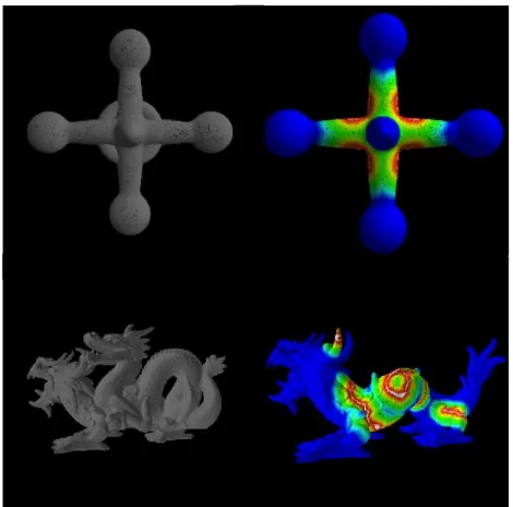
Figure 4. High collision risk area colour based on a rainbow colour map. The collision area colour is white, and it never overlaps with the rainbow colours.
Figure 5. Examples of the colour assignment to visualize the collision risks between point-based surfaces. The top images show the collision of a hubby surface with a torus. The hubby surface is coloured. The bottom images show the collision between two types of dragon. The dragon with horns is coloured.
When executing STEP 3, we need definitions of the collision area colour, the high collision risk area colour, the collision area opacity, and the high collision risk area opacity. Our definitions are as follows.
We adopt a white colour for the collision area and rainbow colours (see Figure 4) for the high collision risk area. This
combination of colours is useful, since the two colours never overlap. For the case that the inter-point distance is exactly ε, that is,for the minimal non-colliding distance, the high collision risk area colour becomes red. Over a proper large threshold inter-point distance, dmax, the point colour is made blue. Below, we call the blue area the collision-free area. Figure 5 shows examples of assigning the abovementioned colours to colliding surfaces.
The collision area (white area) opacity is set to 0.9. The high collision risk area opacity is made dependent on the level of collision risk. From the red area to the orange area, the opacity is set to 0.8. From the yellow area to the green area, the opacity is set to 0.6. For the light blue area, the opacity is set to 0.4. For the remaining blue collision-free areas, which are far from collisions, the opacity is set to 0.2. These opacities are easily realized by the stochastic point-based transparent rendering explained in Section 3.2.
In Figure 5, it is hard to recognize the white collision areas. This is because the areas are thin loops. However, we will see that the tuning of the collision area opacity can make them visible. We will demonstrate this in Section 4 for our target case study.
3.2 Realization of the Collision Area Opacity and the High Collision Risk Area Opacity based on Stochastic Point-based Transparent Rendering
The precise see-through imaging of colliding point clouds can be executed with a correct depth feel with interactive speed by using the stochastic point based transparent rendering (Tanaka et al., 2016), which was proposed for dealing with large-scale laser-scanned point clouds recently. The abovementioned collision area opacity and the high collision risk area opacity can also be realized within the framework of the rendering. When applying the rendering to a given laser-scanned point cloud, first, we randomly divide it to statistically independent subgroups. Then, under the assumption that the point density is uniform in a small local surface segment with an area size S, the opacity of the segment, α, obeys the formula
�=1− 1−
�
�
!
, (1)
where n is the number of points in S for each point subgroup, and s is the size of the area whose image just overlaps one pixel in the image space. Formula (1) indicates that the opacity α is controllable through n. We can realize a higher opacity by increasing n and lower it by decreasing n. The increase of n is easily realized by simply creating a proper number of copies of randomly selected points in the original point cloud. Similarly, the decrease of n is realized by randomly eliminating points in the original point cloud. By tuning the number of points n in S, that is, by tuning the point density in S, the probability that the local surface segment is visible is controlled, which means that the opacity α is tuned.
reliable validation of the simulation based on data acquired by directly measuring the real world.
4. EXPERIMENTAL RESULTS
We applied our visualization method explained in Section 3 to the collision detection simulation of the Ofune-hoko float in its original procession route of the Gion Festival. A point-data model of the Ofune-hoko float is moved in a virtual space constructed by the point cloud of the street acquired by a mobile mapping system (MMS). The Ofune-hoko model was constructed with CAD software and converted into point data by sampling the polygon mesh. The collision detection simulations and visualizations are executed on a PC with an Intel Core i7-5960X (3.10 GHz, 16 GB of memory) CPU.
Figure 6. Left: Raw laser-scanned point cloud of Sanjo Street in Kyoto City (2.3 × 10!
points). Right: Processed point cloud (1.4 × 10! points), in which the ground surface was removed for the preparation of the collision detection simulation.
Figure 7. Point cloud of the Ofune-hoko float (9.7 × 10! points) placed in the scene of Figure 6.
Figure 6 shows the laser-scanned point cloud of Sanjo Street, which is a part of the original float procession route. It is narrow compared with the current route and contains many electric wires, billboards, and other objects, which may collide with the festival float in its procession. Figure 6 (left) shows the raw point cloud data, and Figure 6 (right) shows the processed point
cloud, in which the ground portion was removed to ignore collisions of the float with the ground surface. Note that it is difficult to precisely convert such a complex and large point cloud into a polygon mesh automatically. This means that the conventional polygon-based collision detection algorithm is not suitable for our purpose.
Figure 7 shows the result of placing the point cloud of the Ofune-hoko float in the scene of Figure 6. We can clearly foresee that the float will collide with the electric wires when moving in the street. Collisions with billboards and other objects are also expected when turning at a street intersection.
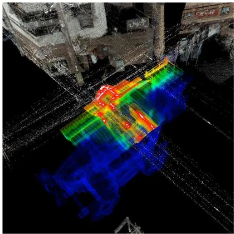
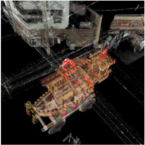
Figure 8. Opaque visualization of the simulated collision between the Ofune-hoko float and the electric wires on Sanjo street. The white colour shows the collision areas, and the rainbow colours show the high collision risk areas.
Figure 9. See-through visualization of the Ofune-hoko float that collides with electric wires. The total number of points used for the visualization is 8.4 × 10!, and the rendering speed is 16.19 fps.
is useful for the city government to consider policies of tuning the route, for example, by shifting the wires. For this purpose, transparent (see-through) rendering with correct depth feel is required.
Figure 9 shows an example of the proposed see-through visualization of collisions. In addition to the collision area (white) and high collision risk area (rainbow colours), the collision free area (blue) is also visualized. Sanjo Street in the background of the Ofune-hoko float is also visualized with its original colours. As explained in Section 3, the opacity is made
highest for the collision areas. For the high collision risk areas, the nearer the portion is to collision, the higher its opacity is. The opacity of the remaining areas is made the lowest. Such properly coloured see-through viewing with the correct depth feel (see Section 3.2) enables us to observe the collisions clearly and together with the whole float and the street.
Figure 10 shows see-through viewing, in which only the collision areas of the Ofune-hoko float are highlighted by the white colour. The remaining parts of the float and the street are visualized with their original colours. By giving higher opacity to the collision areas, we can observe the areas clearly.
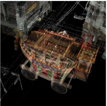
Figures 11 and 12 are the see-though images of the Ofune-hoko float without showing the point cloud of the street. For a detailed analysis of the collisions, this simplification is convenient. In this way, our visualization is executable either for each constituent point cloud or for their fused data.
Figure 13 shows a visualization similar to that of Figure 9 at a different position on the street. The difference is that no collision exists here. Even without any collision, the high collision risk areas are highlighted with rainbow colours, and warning of the existence of such areas is provided.
As shown in the above, our collision simulation and collision visualization have revealed that many collisions will occur if the Ofune-hoko float moves along its original route, Sanjo Street. No collisions with houses or billboards are found when the float moves straight ahead, but we found that collisions can occur when the float turns at an intersection, depending on how the float is moved and rotated. The turning of the Ofune-hoko float at a street intersection is an important festival event called
tsuji-mawashi. Therefore, the investigation of the collisions is highly
required there. Figure 10. See-through collision visualization similar to
Figure 9. Only collision areas of the Ofune-hoko float are given the white highlight colour.
Figure 11. See-through collision visualization of the Ofune-hoko float without showing the point cloud of the street.
Figure 13. See-through visualization of high collision risk areas in a case that no collision exists. The total number of points used for the visualization is 7.8 × 10!
, and the rendering speed is 15.64 fps.
Figure 14 shows a result of investigating the collisions during the virtual tsuji-mawashi. Possible collisions with a house when the float turns at a street intersection are detected and visualized. Although, the collisions are small, we can clearly see the white collision areas. Besides, we can observe that large high collision risk areas, especially the most dangerous red areas, exist.
Figure 14. See-through collision visualization during the turning of the float at a street intersection. The total number of points used for the visualization is 1.1 × 10!, and the rendering speed is 13.21 fps.
Here, we consider another possible tuning of our colour model to highlight collision regions. If the colliding objects are white or nearly white, it is not the best way to simply assign the colour white to their collision areas. In such a case, we highlight the collision areas (white) together with narrow surrounding areas of very high collision risks (red). In this way, the white collision areas becomes apparent and are highlighted successfully (see Fig.15). Using areas of only very high collision risks is also useful for keeping original colours of the colliding objects as much as possible.
Figure 15. Highlighting collision areas (white) together with their surrounding narrow areas of very high collision risks (red).
Finally, we comment on the performance. As shown with some figures, our visualization method is executable at interactive frame rates for point clouds consisting of approximately 10! points. The computational speed of the collision detection simulation is not the focus of this paper, and in fact, our simulation is implemented by focusing more on preciseness than fastness. However, it should be noted here that several seconds are enough for one run of the simulation by using the fundamental acceleration techniques such as the kd-tree and the bounding box. For visualizing colliding regions continuously along the parade route, we can change the position of the float gradually, and apply the proposed method repetitively. Even though the proposed method is not fast enough for real time rendering, it has achieved an interactive rendering speed, which is sufficient for collision investigation in many cases. Besides, because the potential colliding regions along the whole parade route are relatively limited, collision visualization can be focused and carried out only around those areas.
5. CONCLUSION
highlight the collisions and the high collision risk areas are also proposed. Our visualization provides an intuitive way to identify the locations of collisions.
We demonstrated our proposed method by investigating the collisions between the laser-scanned point cloud of Sanjo Street in Kyoto City and a culturally important festival float, Ofune-hoko, that was precisely modelled with CAD software. Based on the visualization results, the possibility of reviving the Ofune-hoko procession along the traditional procession route of the Gion Festival was investigated. For example, many collisions of the float with electric wires were detected, and warning was provided. Possible collisions with a house when the float turns at a street intersection were also revealed.
In the future, we plan to execute our collision visualization during a real-time collision detection simulation (Niwa et al., 2015). For this purpose, we intend to further accelerate the method by utilizing techniques of parallel processing.
It should also be noted that our method is extendable to collision visualization of a point cloud and a polygon mesh by properly calculating distances of each point and its nearest-neighbouring polygon. This extension is clearly useful, if the polygon mesh has already been prepared by, for example, CAD software. In this extension, however, how to apply our point-based precise see-through visualization becomes less trivial. Another possible extension is collision visualization of volume datasets. Once the volumes are properly converted into point clouds, we should be able to apply our collision visualization method to them. This extension is also useful, since many cultural heritage objects are scanned by CT (computed tomography) devices and archived as volume datasets.
ACKNOWLEDGEMENTS
In this paper, images and designs of the Ofune-hoko float are presented with the permission of the Shijo-cho Ofune-hoko Preservation Society. We thank the society for its generous cooperation. We also thank Kyoto City, Prof. H. Masuda, and Prof. R. Xu for their valuable advices. This work was supported in part by JSPS KAKENHI Grant Number 16H02826 and Reseach Gran from Disaster Prevention Research Institute, Kyoto University.
REFERENCES
dos Anjos, R. K., Pereira, J. M.. Oliveira, J. F., 2012. Collision detection on point clouds using a 2.5+D image-based approach, Journal of WSCG, 20(2), pp.145-154.
Figueiredo, M., Oliveira, J., Araujo, B., Pereira, J., 2010. An efficient collision detection algorithm for point cloud models, 20th International Conference on Computer Graphics and
Vision, pp. 43-44.
Hermann, A., Drews, F., Bauer, J., Klemn, S., Roennau, A., Dillmann, R., 2014. Unified GPU voxel collision detection for mobile manipulation planning. Intelligent Robots and Systems (IROS 2014), IEEE/RSJ International Conference on. IEEE, pp.4154-4160.
Ioannides, M., Magnenat-Thalmann, N., Fink, E., Zarnic, R., Yen, A.Y., Quak, E. (editors). Digital Heritage: Progress in Cultural Heritage. Documentation, Preservation, and Protection5th International Conference, EuroMed 2014, Limassol, Cyprus, November 3-8, 2014, Proceedings (Lecture Notes in Computer Science) , Springer, 2014.
Klein, J., Zachmann, G., 2004. Point cloud collision detection, In Computer Graphics Forum, Blackwell Publishing, Inc., 23, 3, pp.567-576.
Niwa, T., Masuda, H., 2016. Interactive Collision Detection for Engineering Plants based on Large-Scale Point-Clouds,
Computer-Aided Design and Applications, Vol.13, No.4, pp.
511-518.
Pan, J., Sucan, A., Chitta, S., Manocha, D., 2013. Real-time collection detection and distance computation on point cloud sensor data. In: Robotics and Automation (ICRA), 2013 IEEE
International Conference, pp. 3593-3599.
Pan, J., Chitta, S., Manocha, D., 2016. Probabilistic Collision Detection Between Noisy Point Clouds Using Robust Classification, In: Robotics Research (Volume 100 of the series Springer Tracts in Advanced Robotics), pp. 77-94.
Radwan, M., Ohrhallinger, S., Wimmer, M., 2014. Efficient Collision Detection While Rendering Dynamic Point Clouds,
Graphics Interface Conference, Canadian Information
Processing Society, pp. 25.
Schauer. J., Nüchter. A., 2014. Efficient point cloud collision detection and analysis in a tunnel environment using kinematic laser scanning and KD Tree search. ISPRS-International Archives of the Photogrammetry, Remote Sensing and Spatial Information Sciences, 1, pp.289-295.
Tanaka, S., Hasegawa, K., Okamoto, N., Umegaki, R., Wang, S., Uemura, M., Okamoto, A., and Koyamada, K., 2016. See-Through Imaging of Laser-scanned 3D Cultural Heritage Objects based on Stochastic Rendering of Large-Scale Point Clouds. ISPRS Ann. Photogramm. Remote Sens. Spatial Inf. Sci., III-5, pp. 73-80.
Zhang, Y. and Pajarola, R., 2007. Image composition for singlepass point rendering. Computers & Graphics 31(2), pp. 175–189.