R&D Priorities and Gaps
HYDROGEN
PRODUCTION
AND
STORAGE
H I A
R&D Priorities and Gaps
PRODUCTION
AND
November 1974 within the framework of the Organisation for Economic Co-operation and Development (OECD) to implement an international energy programme.
It carries out a comprehensive programme of energy co-operation among twenty-six of the OECD’s thirty member countries. The basic aims of the IEA are:
• to maintain and improve systems for coping with oil supply disruptions;
• to promote rational energy policies in a global context through co-operative relations with non-member countries, industry and international organisations;
• to operate a permanent information system on the international oil market;
• to improve the world’s energy supply and demand structure by developing alternative energy sources and increasing the efficiency of energy use;
• to assist in the integration of environmental and energy policies.
The IEA member countries are: Australia, Austria, Belgium, Canada, the Czech Republic, Denmark, Finland, France, Germany, Greece, Hungary, Ireland, Italy, Japan, the Republic of Korea, Luxembourg, the Netherlands, New Zealand, Norway, Portugal, Spain, Sweden, Switzerland, Turkey, the United Kingdom, the United States. The European Commission takes part in the work of the IEA.
O R G A N I S AT I O N F O R E C O N O M I C C O - O P E R AT I O N A N D D E V E LO P M E N T
The OECD is a unique forum where the governments of thirty democracies work together to address the economic, social and environmental challenges of globalisation. The OECD is also at the forefront of efforts to understand and to help governments respond to new developments and concerns, such as corporate governance, the information economy and the challenges of an ageing population. The Organisation provides a setting where governments can compare policy experiences, seek answers to common problems, identify good practice and work to co-ordinate domestic and international policies.
The OECD member countries are: Australia, Austria, Belgium, Canada, the Czech Republic, Denmark, Finland, France, Germany, Greece, Hungary, Iceland, Ireland, Italy, Japan, Korea, Luxembourg, Mexico, the Netherlands, New Zealand, Norway, Poland, Portugal, the Slovak Republic, Spain, Sweden, Switzerland, Turkey, the United Kingdom and the United States. The European Commission takes part in the work of the OECD.
© OECD/IEA, 2005
No reproduction, copy, transmission or translation of this publication may be made without written permission. Applications should be sent to:
International Energy Agency (IEA), Head of Publications Service, 9 rue de la Fédération, 75739 Paris Cedex 15, France.
BACKGROUND AND ACKNOWLEDGEMENTS
This review of priorities and gaps in hydrogen production and storage R&D has been prepared by the IEA Hydrogen Implementing Agreement in the context of the activities of the IEA Hydrogen Co-ordination Group.
The Hydrogen Implementing Agreement (HIA) is the R&D co-operation programme on hydrogen technologies established by IEA member countries in 1977 under the IEA framework for international collaboration on energy technology. For more than 25 years, the HIA has been working to promote international co-operation and to carry out innovative research, development and demonstration (RD&D) of hydrogen technologies with the aim of accelerating widespread utilisation of hydrogen as a clean energy carrier.
The Hydrogen Co-ordination Group (HCG) is the IEA advisory policy committee on hydrogen and fuel cells established by the IEA in April 2003 with the aim of improving policy co-ordination and R&D co-operation among IEA member countries. Members of the HCG are representatives of IEA countries and relevant IEA Implementing Agreements.
The HCG programme of work aims to:
● Review national programs in IEA member countries;
● Review ongoing activities in the IEA Implementing Agreements to identify needed work on
critical-path technologies;
● Recommend additional co-operative activities within the context of the IEA’s technology
collaboration program; and
● Identify the analysis and support needed to help guide the work of the IEA.
The first task was completed in December 2004 with the publication by the IEA Secretariat of the report Hydrogen and Fuel Cells: National R&D Programmes, which built on the information provided by HCG members on the R&D and policy programmes of IEA member countries.
The present publication, Hydrogen Production and Storage - R&D Priorities and Gaps, was prepared by the Hydrogen Implementing Agreement in the context of tasks 2 & 3 of the above HCG programme of work. It includes two papers that highlight priorities and needs in the R&D activities of hydrogen production and storage technologies.
The fourth task will be completed by the IEA Secretariat in December 2005 with the publication of Prospects for Hydrogen and Fuel Cells, a quantitative analysis that uses the IEA Energy Technology Perspectives (ETP) model to explore the possible roles of hydrogen and fuel cells in future energy scenarios.
HYDROGEN PRODUCTION R&D:
PRIORITIES AND GAPS
Trygve Riis(1)and Elisabet F. Hagen(2)
Preben J. S. Vie(3)and Øystein Ulleberg(3)(Corresponding authors)
A B S T R A C T
■ This paper offers an overview of the technologies for hydrogen production. The technologies discussed are reforming of natural gas; gasification of coal and biomass; and the splitting of water by water-electrolysis, photo-electrolysis, photo-biological production and high-temperature decomposition. For all hydrogen production processes, there is a need for significant improvement in plant efficiencies, for reduced capital costs and for better reliability and operating flexibility.
■ Water electrolysis and natural gas reforming are the technologies of choice in the current and near term. They are proven technologies that can be used in the early phases of building a hydrogen infrastructure for the transport sector. Small-scale natural gas reformers have only limited commercial availability, but several units are being tested in demonstration projects. In the medium to long term, centralised fossil fuel-based production of hydrogen, with the capture and storage of CO2, could be the technology of choice. However, the capture and storage of CO2is not yet technically and commercially proven. Further R&D on the processes of absorption and separation are required.
■ Other methods for hydrogen production are further away from commercialisation and need additional R&D. The production of hydrogen from biomass needs additional focus on the preparation and logistics of the feed, and such production will probably only be economical at a larger scale. Photo-electrolysis is at an early stage of development, and material costs and practical issues have yet to be solved. The photo-biological processes are at a very early stage of development with only low conversion efficiencies obtained so far. High-temperature processes need further materials development that focuses on high-temperature membranes and heat exchangers.
INTRODUCTION
Hydrogen can be produced from a variety of feedstocks. These include fossil resources, such as natural gas and coal, as well as renewable resources, such as biomass and water with input from renewable energy sources (e.g.sunlight, wind, wave or hydro-power). A variety of process technologies can be used, including chemical, biological, electrolytic, photolytic and thermo-chemical. Each technology is in a different stage of development, and each offers unique opportunities, benefits
1. The Research Council of Norway, PO Box 2700, St. Hanshaugen NO–0131 Oslo, Norway. 2. Norsk Hydro ASA, NO-0246 Oslo, Norway.
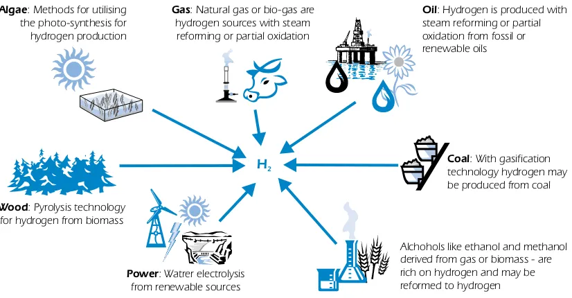
and challenges. Local availability of feedstock, the maturity of the technology, market applications and demand, policy issues, and costs will all influence the choice and timing of the various options for hydrogen production. An overview of the various feedstocks and process technologies is presented in Figure 1.
Figure 1
Some feedstock and process alternatives
H2
Gas: Natural gas or bio-gas are
hydrogen sources with steam reforming or partial oxidation
Algae: Methods for utilising
the photo-synthesis for hydrogen production
Wood: Pyrolysis technology
for hydrogen from biomass
Power: Watrer electrolysis from renewable sources
Coal: With gasification
technology hydrogen may be produced from coal
Alchohols like ethanol and methanol derived from gas or biomass - are rich on hydrogen and may be reformed to hydrogen
Oil: Hydrogen is produced with steam reforming or partial oxidation from fossil or renewable oils
Source: Hydro.
Several technologies are already available in the marketplace for the industrial production of hydrogen. The first commercial technology, dating from the late 1920s, was the electrolysis of water to produce pure hydrogen. In the 1960s, the industrial production of hydrogen shifted slowly towards a fossil-based feedstock, which is the main source for hydrogen production today.
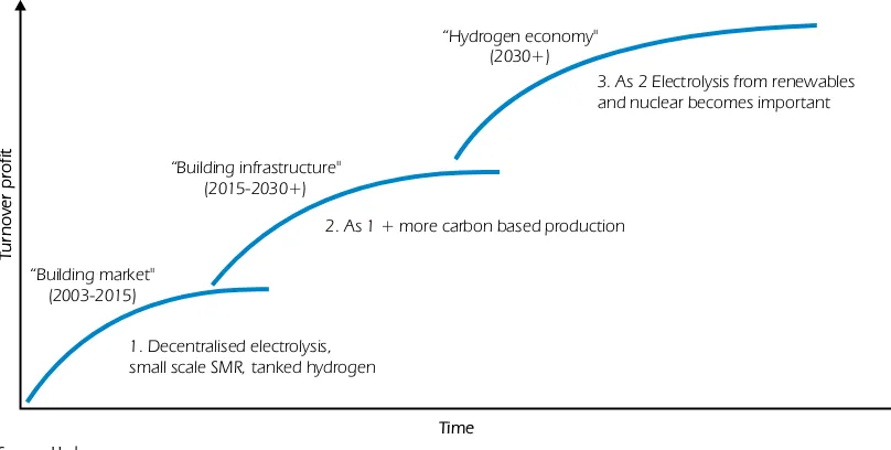
In Figure 2, a future hydrogen pathway is illustrated. Large-scale hydrogen production is probable only in the longer term. In the short and medium term, the production options for hydrogen are first based on distributed hydrogen production from the electrolysis of water and on the reforming of natural gas and coal. Larger centralised hydrogen production plants are more likely to be introduced at a later stage. These plants will probably be based on biomass or fossil fuels with CO2capture and storage.
The IEA Hydrogen Implementing Agreement (HIA) focuses on the following hydrogen production activities:
● H2from fossil energy sources.
– Large scale, with CO2 capture and storage (in collaboration with the IEA Green House Gas Implementing Agreement programme – GHG)
– Small scale, with distributed generation
● H2from biomass.
● Photo-electrolysis (photolysis).
A new area of focus within the HIA is the high-temperature production of hydrogen.
This paper aims to provide an overview of the most important issues regarding the production of hydrogen, the needs for research and development (i.e. current gaps), and the priorities for further development and use. This overview is not, however, all-inclusive, and detailed descriptions of processes and R&D needs should be sought in specialist papers discussing each technology in more detail.
HYDROGEN FROM FOSSIL FUELS
Hydrogen can be produced from most fossil fuels. The complexity of the processes varies, and in this chapter hydrogen production from natural gas and coal is briefly discussed. Since carbon dioxide is produced as a by-product, the CO2should be captured to ensure a sustainable (zero-emission) process. The feasibility of the processes will vary with respect to a centralised or distributed production plant.
Production from natural gas
Hydrogen can currently be produced from natural gas by means of three different chemical processes:
● Steam reforming (steam methane reforming – SMR).
● Partial oxidation (POX).
● Autothermal reforming (ATR).
Although several new production concepts have been developed, none of them is close to commercialisation.
Figure 2
Main hydrogen pathways: the long term perspective
“Building market" (2003-2015)
“Building infrastructure" (2015-2030+)
“Hydrogen economy" (2030+)
1. Decentralised electrolysis, small scale SMR, tanked hydrogen
2. As 1 + more carbon based production
3. As 2 Electrolysis from renewables and nuclear becomes important
Time
Tur
nover
profit
Steam reforming involves the endothermic conversion of methane and water vapour into hydrogen and carbon monoxide (2.1). The heat is often supplied from the combustion of some of the methane feed-gas. The process typically occurs at temperatures of 700 to 850 °C and pressures of 3 to 25 bar. The product gas contains approximately 12 % CO, which can be further converted to CO2 and H2through the water-gas shift reaction (2.2).
CH4+ H2O + heat ➞CO + 3H2 (2.1)
CO + H2O ➞CO2+ H2+ heat (2.2)
Partial oxidation of natural gas is the process whereby hydrogen is produced through the partial combustion of methane with oxygen gas to yield carbon monoxide and hydrogen (2.3). In this process, heat is produced in an exothermic reaction, and hence a more compact design is possible as there is no need for any external heating of the reactor. The CO produced is further converted to H2 as described in equation (2.2).
CH4+ 1/2O2➞CO + 2H2+ heat (2.3)
Autothermal reforming is a combination of both steam reforming (2.1) and partial oxidation (2.3). The total reaction is exothermic, and so it releases heat. The outlet temperature from the reactor is in the range of 950 to 1100 °C, and the gas pressure can be as high as 100 bar. Again, the CO produced is converted to H2through the water-gas shift reaction (2.2). The need to purify the output gases adds significantly to plant costs and reduces the total efficiency.
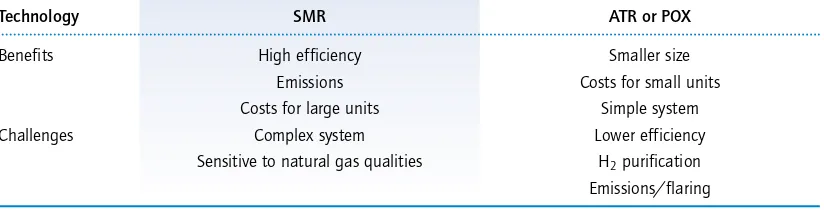
Each one of the above processes has certain benefits and challenges, which are summarised in Table 1.
Table 1
Comparison of technologies for H2 production from natural gas
Technology SMR ATR or POX
Benefits High efficiency Smaller size Emissions Costs for small units Costs for large units Simple system Challenges Complex system Lower efficiency
Sensitive to natural gas qualities H2purification Emissions/flaring
Production from coal
Hydrogen can be produced from coal through a variety of gasification processes (e.g. fixed bed, fluidised bed or entrained flow). In practice, high-temperature entrained flow processes are favoured to maximise carbon conversion to gas, thus avoiding the formation of significant amounts of char, tars and phenols. A typical reaction for the process is given in equation (2.4), in which carbon is converted to carbon monoxide and hydrogen.
Since this reaction is endothermic, additional heat is required, as with methane reforming. The CO is further converted to CO2and H2through the water-gas shift reaction, described in equation (2.2). Hydrogen production from coal is commercially mature, but it is more complex than the production of hydrogen from natural gas. The cost of the resulting hydrogen is also higher. But since coal is plentiful in many parts of the world and will probably be used as an energy source regardless, it is worthwhile to explore the development of clean technologies for its use.
Capture and storage of CO
2Carbon dioxide is a major exhaust in all production of hydrogen from fossil fuels. The amount of CO2will vary with respect to the hydrogen content of the feedstock. To obtain a sustainable (zero-emission) production of hydrogen, the CO2should be captured and stored. This process is known as de-carbonisation. There are three different options to capture CO2in a combustion process:
● Post-combustion.The CO2can be removed from the exhaust gas of the combustion process in a conventional steam turbine or CCGT (combined cycle gas turbine) power plant. This can be done via the “amine” process, for example. The exhaust gas will contain large amounts of nitrogen and some amounts of nitrogen oxides in addition to water vapour, CO2and CO.
● Pre-combustion.CO2is captured when producing hydrogen through any of the processes discussed above.
● Oxyfuel-combustion.The fossil fuel is converted to heat in a combustion process in a conventional steam turbine or CCGT power plant. This is done with pure oxygen as an oxidiser. Mostly CO2 and water vapour are produced in the exhaust or flue gases, and CO2can be easily separated by condensing the water vapour.
In post-combustion and oxyfuel-combustion systems, electricity is produced in near-conventional steam and CCGT power plants. The electricity produced could then be used for water electrolysis. If the capture and storage of CO2 is applied to an energy conversion process of relatively low efficiency, and the electricity is used to electrolyse water, then the overall efficiency of fuel to hydrogen would not exceed 30%.
The captured CO2can be stored in geological formations like oil and gas fields, as well as in aquifers,4 but the feasibility and proof of permanent CO2storage are critical to the success of de-carbonisation.
The choice of the transportation system for the CO2(pipeline, ship or combined) will largely depend on the site chosen for the production plant and the site chosen for storage.
HYDROGEN FROM SPLITTING OF WATER
Hydrogen can be produced from the splitting of water through various processes. This paper briefly discusses water electrolysis, photo-electrolysis, photo-biological production and high-temperature water decomposition.
Water electrolysis
Water electrolysis is the process whereby water is split into hydrogen and oxygen through the application of electrical energy, as in equation (3.1). The total energy that is needed for water
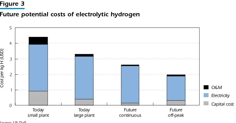
electrolysis is increasing slightly with temperature, while the required electrical energy decreases. A high-temperature electrolysis process might, therefore, be preferable when high-temperature heat is available as waste heat from other processes. This is especially important globally, as most of the electricity produced is based on fossil energy sources with relatively low efficiencies. Future potential costs for electrolytic hydrogen are presented in Figure 3, where the possibilities to considerably reduce the production cost are evident.
H2O + electricity ➞H2+ 1/2O2 (3.1)
Figure 3
Future potential costs of electrolytic hydrogen
0 1 2 3 4 5
Today small plant
Cost
per
kg
H
(USD)
Today large plant
Future continuous
Future off-peak
O&M
Electricity
Capital cost
Source: US DoE.
Alkaline electrolysis
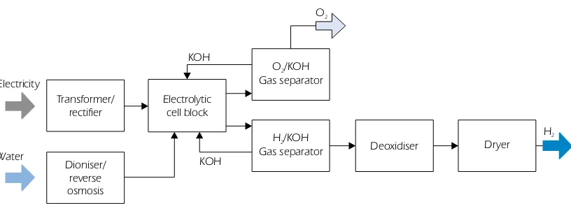
Alkaline electrolysers use an aqueous KOH solution (caustic) as an electrolyte that usually circulates through the electrolytic cells. Alkaline electrolysers are suited for stationary applications and are available at operating pressures up to 25 bar. Alkaline electrolysis is a mature technology, with a significant operating record in industrial applications, that allows remote operation.
The following reactions take place inside the alkaline electrolysis cell:
Electrolyte: 4H2O ➞4H++ 4OH– (3.1)
Cathode: 4 H++ 4e–➞2H2 (3.2)
Anode: 4OH–➞O2+ 2H2O + 4e– (3.3)
Sum: 2H2O ➞O2+ 2H2 (3.4)
Polymer electrolyte membrane (PEM) electrolysis
The principle of PEM electrolysis is presented in equations (3.6) and (3.7). PEM electrolysers require no liquid electrolyte, which simplifies the design significantly. The electrolyte is an acidic polymer membrane. PEM electrolysers can potentially be designed for operating pressures up to several hundred bar, and are suited for both stationary and mobile applications. The main drawback of this technology is the limited lifetime of the membranes. The major advantages of PEM over alkaline electrolysers are the higher turndown ratio5, the increased safety due to the absence of
KOH electrolytes, a more compact design due to higher densities, and higher operating pressures.
anode: H2O ➞1/2O2+ 2 H++ 2e– (3.6)
cathode: 2H++ 2e–➞H2 (3.7)
With relatively high cost, low capacity, poor efficiency and short lifetimes, the PEM electrolysers currently available are not as mature as alkaline electrolysers. It is expected that the performance of PEM electrolysers can be improved significantly by additional work in materials development and cell stack design.
High-temperature electrolysis
High-temperature electrolysis is based on technology from high-temperature fuel cells. The electrical energy needed to split water at 1000 °C is considerably less than electrolysis at 100 °C. This means that a high-temperature electrolyser can operate at significantly higher overall process efficiencies than regular low-temperature electrolysers.
A typical technology is the solid oxide electrolyser cell (SOEC). This electrolyser is based on the solid oxide fuel cell (SOFC), which normally operates at 700 to 1000 °C. At these temperatures, the electrode reactions are more reversible, and the fuel cell reaction can more easily be reversed to an electrolysis reaction. Attempts are currently underway to develop systems in which some of the electricity consumed by the electrolyser can be replaced with the heat available from geothermal, solar or natural gas sources, thus reducing the consumption of electricity significantly.
Figure 4
Process diagram of alkaline electrolysis
Water Electricity
KOH
KOH Transformer/
rectifier Electrolyticcell block
O /KOH Gas separator2
H /KOH Gas separator2
H2 O2
Deoxidiser Dryer Dioniser/
reverse osmosis
Similar to the main challenges for SOFCs, the main R&D needs for SOECs relate to materials development and thermo-mechanical stress within the functional ceramic materials.
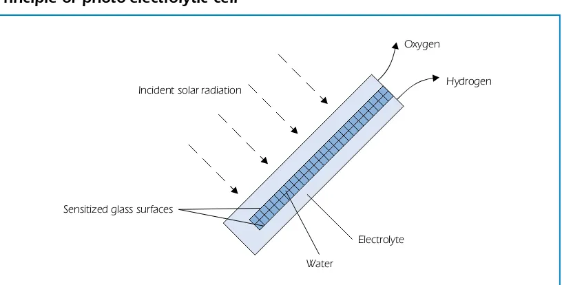
Photo-electrolysis (photolysis)
Photovoltaic (PV) systems coupled to electrolysers are commercially available. The systems offer some flexibility, as the output can be electricity from photovoltaic cells or hydrogen from the electrolyser. Direct photo-electrolysis represents an advanced alternative to a PV-electrolysis system by combining both processes in a single apparatus. This principle is illustrated in Figure 5. Photo-electrolysis of water is the process whereby light is used to split water directly into hydrogen and oxygen. Such systems offer great potential for cost reduction of electrolytic hydrogen, compared with conventional two-step technologies.
Figure 5
Principle of photo-electrolytic cell
Incident solar radiation
Sensitized glass surfaces
Hydrogen Oxygen
Water
Electrolyte
Source: Hydrogen Solar Production Company Inc.
Fundamental and applied R&D efforts in relation to materials science and systems engineering for photo-electrochemical cells (PEC) are currently being undertaken world wide, with at least 13 OECD countries maintaining PEC-related R&D projects and/or entire programs. The IEA-HIA co-ordinates and manages a significant part of these R&D efforts in a collaborative, task-shared Annex. Four major PEC concept areas are being studied, comprising two-photon tandem systems, monolithic multi-junction systems, dual-bed redox systems, and one-pot two-step systems. While the first two concepts employ thin-film-on-glass devices immersed in water, the latter two concepts are based on the application of photosensitive powder catalysts suspended in water. Various laboratory-scale PEC devices have been developed over the past couple of years, thus far demonstrating solar-to-hydrogen conversion efficiencies of up to 16%.
material commercially exists for water splitting, tailored materials have to be engineered. Combinatorial chemistry approaches offer fast-tracking experimental options for the necessary materials screening, while modelling capabilities of photo-oxidation based on quantum transition theory need to be developed. Most important, there is a need for fundamental research on semiconductor doping for band-gap shifting and surface chemistry modification, including studies of the associated effects on both surface and bulk semi-conducting properties. Corrosion and photo-corrosion resistance present further significant R&D challenges to be addressed, with most of the promising materials options at hand. Current-matching between anode and cathode, in addition to ohmic resistance minimisation, requires considerable systems design as well as sophisticated engineering solutions. Optimisation of fluid dynamics (with its effects on mass and energy transfer) and gas collection and handling (with its effects on operational safety) will demand major conceptual and application-specific R&D attention.
Photo-biological production (biophotolysis)
Photo-biological production of hydrogen is based on two steps: photosynthesis (3.8) and hydrogen production catalysed by hydrogenases (3.9) in, for example, green algae and cyanobacteria. Long-term basic and applied research is needed in this area, but if successful, a long-Long-term solution for renewable hydrogen production will result. It is of vital importance to understand the natural processes and the genetic regulations of H2production. Metabolic and genetic engineering may be used to demonstrate the process in larger bioreactors. Another option is to reproduce the two steps using artificial photosynthesis.
Photosynthesis: 2H2O ➞4H++ 4e–+ O2 (3.8)
Hydrogen Production: 4H++ 4e–➞2H2 (3.9)
Figure 6
Principle of photo-biological hydrogen production
Nutrient recycle
Algae Algae
Algae recycle CO2 O2
Sunlight
Algae production bioreactor (light-aerobic)
Algae concentrator and adaptation chamber
(dark-anaerobic) Hydrogen photobioreactor(light-anaerobic)
Sunlight
H2
High-temperature decomposition
● Thermo-chemical cycles.
● Hybrid systems coupling thermal decomposition and electrolytic decomposition.
● Direct catalytic decomposition of water with separation via a ceramic membrane (“thermo-physic cycle”).
● Plasma-chemical decomposition of water in a double-stage CO2cycle.
For these processes, efficiencies above 50 % can be expected and could possibly lead to a major decrease of hydrogen production costs. The main technical issues for these high-temperature processes relate to materials development for corrosion resistance at high temperatures, high-temperature membrane and separation processes, heat exchangers, and heat storage media. Design aspects and safety are also important for high-temperature processes.
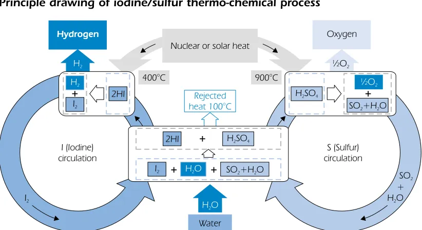
Thermo-chemical water splitting
Thermo-chemical water splitting is the conversion of water into hydrogen and oxygen by a series of thermally driven chemical reactions. Thermo-chemical water-splitting cycles have been known for the past 35 years. They were extensively studied in the late 1970s and 1980s, but have been of little interest in the past 10 years. While there is no question about the technical feasibility and the potential for high efficiency, cycles with proven low cost and high efficiency have yet to be developed commercially. An example of a thermo-chemical process is the iodine/sulphur cycle, outlined in equations (3.10), (3.11) and (3.12) and Figure 7. For this process, the research and development needs are to capture the thermally split H2, to avoid side reactions and to eliminate the use of noxious substances. The corrosion problems associated with the handling of such materials are likely to be extremely serious.
(850 °C): H2SO4➞SO2+ H2O + 1/2O2 (3.10)
(120 °C): I2+ SO2+ 2H2O ➞H2SO4+ 2HI (3.11)
(450 °C): 2HI ➞I2+ H2 (3.12)
SUM: H2O ➞H2+ 1/2O2
Figure 7
Principle drawing of iodine/sulfur thermo-chemical process
Hydrogen 900°C 400°C I2 Water +
Nuclear or solar heat
Oxygen ½O2 Rejected heat 100°C S (Sulfur) circulation SO + H O 2 2 H2 2HI I (Iodine) circulation
H O2
H2
I2
2HI + H SO2 4
+ + SO +H O2 2
I2 H O2
+ +
½O2
H SO2 4
BIOMASS TO HYDROGEN
In biomass conversion processes, a hydrogen-containing gas is normally produced in a manner similar to the gasification of coal, as in equation (2.4). However, no commercial plants exist to produce hydrogen from biomass. Currently, the pathways followed are steam gasification (direct or indirect), entrained flow gasification, and more advanced concepts such as gasification in supercritical water, application of thermo-chemical cycles, or the conversion of intermediates (e.g. ethanol, bio-oil or torrified wood). None of the concepts have reached a demonstration phase for hydrogen production.
Biomass gasification is an R&D area shared between H2 production and biofuels production. Gasification and pyrolysis are considered the most promising medium-term technologies for the commercialisation of H2production from biomass. A typical flow sheet for the production of hydrogen from biomass is presented in Figure 8. In terms of its energy requirements, the drying of biomass might not be justifiable; therefore, other pathways based on wet biomass are being sought as well.
Biomass feedstocks are unrefined products with inconsistent quality and poor quality control. The production methods vary according to crop type, location and climatic variations. Erratic fuels have contributed to the difficulties in technological innovation, since less homogenous and low-quality fuels need more sophisticated conversion systems. There is a need to rationalise the production and preparation of fuel to produce more consistent, higher-quality fuels that can be described by common standards. Large-scale systems tend to be suitable for cheaper and lower quality fuels, while smaller plants tend to require higher levels of fuel quality and better fuel homogeneity. A better understanding of this relationship, and the specific tolerances that each technology can accommodate, is needed.
Figure 8
Generic flow sheet for methanol, hydrogen or FT diesel production via biomass gasification
Biomass
Methanol
Drying and
chipping Gasification andgas cleaning Reforming, shifting,CO separation2
Hydrogen
FT diesel
Electricity Catalysis,
separation
Separation Recycle
Refining Catalysis,
separation
Gas turbine or boiler
Steam turbine
Source: CIRAD Forestry Department/HIA annex 16 – subtask B.
Several developments are needed to improve the economics of production processes and the logistics of handling a biomass feedstock:
● Gasification of biomass. This is not specific for hydrogen, but relates to general biomass and renewables pathways and research.
● Raw gas handling and clean-up.
● Interface issues and system integration. One should also investigate the relationship between the production scale and the fuel quality requirements and tolerances that can be accommodated for the respective technologies.
CENTRALISED HYDROGEN PRODUCTION
Large-scale, industrial hydrogen production from all fossil energy sources can be considered a commercial technology for industrial purposes, though not yet for utilities. Hydrogen production at a large scale has the potential for relatively low unit costs, although the hydrogen production cost from natural gas in medium sized plants may be reduced towards the cost of large-scale production. An important challenge is to decarbonise the hydrogen production process. CO2capture and storage options are not fully technically and commercially proven. They require R&D on absorption or separation processes and process line-up, as well as acceptance for CO2storage. It is also important to increase plant efficiency, reduce capital costs and enhance reliability and operating flexibility. A principle sketch of hydrogen distribution from a natural gas-based centralised hydrogen production plant is presented in Figure 9.
Figure 9
Principle sketch for large scale centralised hydrogen production with CO2 capture
Hydrogen plant
Natural gas power plant with CO
management2
CO handling2 CO to EOR and/or storage2 Hydrogen pipeline
Hydrogen FC CHP Natural gas pipeline
Fuel cell ship
Natural gas reservoir
Fuel cells
Gas turbines
Geological reservoir
Hydrogen
(IGCC) plants. The IGCC plant is the most advanced and efficient solution in which the carbon in the fuel is removed and the hydrogen is produced in a pre-combustion process.
However, successful centralised hydrogen production requires large market demand, as well as the construction of a new hydrogen transmission and distribution infrastructure and pipeline for CO2 storage.
In the future, centralised hydrogen production from high-temperature processes based on renewable energy and waste heat can also be an option to enhance sustainability and remove the need for capture and storage of CO2.
DISTRIBUTED HYDROGEN PRODUCTION
Distributed hydrogen production can be based on both water electrolysis and the natural gas processes discussed above. The benefit would be a reduced need for the transportation of hydrogen fuel, and hence less need for the construction of a new hydrogen infrastructure. Distributed production would also utilise existing infrastructure, such as natural gas or water and electric power. However, the production costs are higher for the smaller-capacity production facilities, and the efficiencies of production will probably be lower than those of centralised plants. In addition, carbon capture and sequestration would be more difficult and costly in small fossil-fuelled plants. Also, it is unlikely that CO2from fossil fuels will be captured and stored when hydrogen is produced from distributed reformers. The R&D needs for distributed hydrogen production are summarised in Table 2.
Small-scale reformers will enable the use of existing natural gas pipelines for the production of hydrogen at the site of the consumer. Such reformers therefore represent an important technology for the transition to a larger hydrogen supply. The availability of commercial reformers is limited and most reformers are currently in an R&D stage. Further development and R&D is essential to meet customer requirements.
Table 2
Overview of R&D needs for distributed hydrogen production systems
R&D needs H2from H2from
natural gas water electrolysis
Minimise cost x x
Minimise footprint and height x x
Minimise CO2and other emissions x
Develop user-friendly, automated plants x x Improve the reliability and durability of operation x x Optimise the service, training and maintenance program x x Develop safety, standards and certification x x Increase system energy-efficiency x x Ensure hydrogen gas quality and requirements
are met by current technology x
especially important market requirement. Suppliers have significantly reduced the footprint and height. The optimum system for the future would be an underground system that requires a space of 10 ×3 ×3 meters for a capacity of 500 – 700 Nm3/hour. The target is within reach with some
additional R&D effort. However, the space required by hydrogen production is a disadvantage for the technology when compared with conventional trucked-in systems for gasoline/diesel or hydrogen. Minimising footprint and visibility has been an important R&D priority. Also, codes and standards for hydrogen production and storage will need to be revised to permit the use of enclosed or underground spaces, at least in some countries.
CONCLUSIONS AND RECOMMENDATIONS
This paper has provided an overview of potential development of hydrogen production from water splitting and fossil/hydrocarbon fuels, as well as the remaining R&D gaps that must be overcome. For all hydrogen production processes, there is a need for significant improvement in plant efficiencies, for reduced capital costs and for better reliability and operating flexibility.
The commercial cost target for hydrogen production is 0.30 USD/kg H2, corresponding to an energy price for gasoline of 2.5 USD/GJ in a competitive market. The hydrogen-producing technologies have at best only 2-3 times higher production costs. Distributed hydrogen production based on reforming is often competitive with electrolysis, as reforming costs 16-29 USD/GJ and electrolysis costs 20-40 USD/GJ, depending on investment and energy costs. In large-scale production plants based on natural gas, the production cost is 5-8 USD/GJ. Distributed hydrogen production can be competitive with centrally produced hydrogen (i.e. large-scale natural gas reforming) depending on the transportation distance. For example, transportation of compressed hydrogen gas for 100 miles will add 15-20 USD/GJ to the cost.
In the current and near term, water electrolysis and small-scale natural gas reformers are suitable. Water electrolysis is a proven technology that can be used in the early phases of building a hydrogen infrastructure for the transport sector. Small-scale natural gas reformers have only limited proven and commercial availability, but several units are being tested in demonstration projects.
In the medium to long term, hydrogen production based on centralised fossil fuel production with CO2capture and storage is feasible. The capture and storage of CO2is not yet technically or commercially proven and requires further R&D on absorption/separation processes and process line-up.
The other methods for hydrogen production are further away from commercialisation and need additional R&D. Production from biomass needs additional focus on the preparation and logistics of the feed, and will probably only be economical on a large scale. Photo-electrolysis is at an early stage of development, and materials cost and practical issues have to be solved. Photo-biological processes are at a very early stage of development and have, so far, obtained only low conversion efficiencies. High-temperature processes need further materials development focusing, for example, on high-temperature membranes and heat exchangers.
ACKNOWLEDGEMENTS
HYDROGEN STORAGE R&D:
PRIORITIES AND GAPS
Trygve Riis(6)and Gary Sandrock(7)
Øystein Ulleberg(8)and Preben J.S. Vie(8) (Corresponding authors)
A B S T R A C T
■ The objective of this paper is to provide a brief overview of the possible hydrogen storage options available today and in the foreseeable future. Hydrogen storage can be considered for onboard vehicular, portable, stationary, bulk, and transport applications, but the main focus of this paper is on vehicular storage, namely fuel cell or ICE/electric hybrid vehicles. The technical issues related to this application are weight, volume, discharge rates, heat requirements, and recharging time. Another important merit factor is cost. The paper discusses in detail the advantages and disadvantages of the various hydrogen storage options for vehicular storage, identifies the main technological gaps, and presents a set of concrete recommendations and priorities for future research and development. The main conclusions can be used as input to future policy documents on hydrogen storage.
INTRODUCTION
The main objective of this paper is to provide an overview of the three principal forms of hydrogen storage (gas, liquid, and solid), with a focus on the technology gaps and R&D priorities related to the various approaches. Figure 10 compares the volumetric and gravimetric H2density of some of
the most common storage options, and clearly shows the theoretical potential of low volumetric densities for solid-state storage systems. However, there are further system requirements that need to be fulfilled. Table 3 shows the practical H2storage system and media targets for fuel cells as
6. The Research Council of Norway, PO Box 2700, St. Hanshaugen NO–0131 Oslo, Norway. 7. IEA HIA Task 17 Operating Agent, SunaTech, Inc., 113 Kraft Pl., Ringwood, NJ 07456, USA. 8. Institute for Energy Technology, PO Box 40, NO–2027 Kjeller, Norway.
Table 3
Selected H2-storage system and media targets for fuel cell vehicles†
Property Units 2010 2007 2006
USA Japan IEA*
System density (by weight) wt.% H2 6 3 –
System density (by volume) kg H2/m3 45 – –
System cost US$/kg H2 133 – –
Refuelling time minutes 3 – –
Medium density (by weight) wt.% H2 – 5.5 5.0
H2liberation temperature ˚C – 150 80
† 500 km range = ca. 5-13 kg stored H2.
determined by the United States, Japan and the IEA, while Table 4 shows the most probable (state-of-the-art) H2storage methods today. This paper provides the key technical details for current
technologies, as well as other and more-novel H2storage technologies.
Figure 10
Density for various H2 storage forms
Gravimetric H density (mass%)2
Volumetric H density (kg H m) 22 3 BaReH <373 K, 1 bar
9
FeTiH 300 K, 1.5 bar
1.7
LaNi H 300 K, 2 bar
5 6
Mg FeH2 6
620 K, 1 bar
Mg NiH2 4
550 K, 4 bar
NaAlH dec. >520K 4 LiAlH dec. 400K 4 LiBlH dec. 553K 4 LiH dec. 650K KBH dec. 580K 4 MgH2
620 K, 5 bar
NaBH dec. 680 K
4
C H8 18 liq.
C H b.p. 272 K
4 10 liq.
CH b.p. 112 K
4 liq. Pressurised H (composite material) p [bar] 2 Gas H physisorbed on carbon 2 H chemisorbed on carbon 2 H 20.3 K 2 liq. AI(BH ) dec. 373 K m.p. 208 K 4 3 CnanoH
0.95 2000 1000 800 500 200 130
density 5 g cm-3
2 g cm-3
1 g cm-3
0.7 g cm-3
20000 5000
160
0 5 10 15 20 25
140 120 100 80 60 40 20 0
Source: Schlapbach and Züttel, Nature, 2001 [1].
Figure 11 shows an example of a vehicular hydrogen fuel cell system using some form of hydride storage. It is important to note that all H2storage systems, except gaseous systems, require a heat
exchanger. In general, heat must be added during discharging and removed during recharging. In practical systems, waste heat from the fuel cell or internal combustion engine (ICE) should be utilised. Hence, the propulsion technology dictates the required discharge temperature of the hydrogen storage medium (e.g.approximately 80 ˚C for PEM fuel cells). A key challenge is the ability to recharge the system in 3 minutes (one of the targets in Table 3). A typical 5 kg H2-hydride bed, for instance, would
require 500 kW of heat removal. That means that off-board recharging may be required.
Table 4
State-of-the-art technology and estimates for system volumes and weights for vehicular compressed gas, cryogenic liquid, and hydride storage of 3 kg H2†
Technology Volume Weight Density [litres] [kg] [Wt. % H2]
35 MPa (350 bar) compressed H2 145 45 6.7
70 MPa (700 bar) compressed H2 100 50 6.0
Cryogenic liquid H2 90 40 7.5
Low-temperature metal hydride 55 215 1.4
GASEOUS HYDROGEN
The most common method to store hydrogen in gaseous form is in steel tanks, although lightweight composite tanks designed to endure higher pressures are also becoming more and more common. Cryogas, gaseous hydrogen cooled to near cryogenic temperatures, is another alternative that can be used to increase the volumetric energy density of gaseous hydrogen. A more novel method to store hydrogen gas at high pressures is to use glass microspheres. The next two sections provide further details on two of the most promising methods to store hydrogen gas under high pressure: composite tanks and glass microspheres.
Composite tanks
A schematic of a typical high-pressure, C-fibre-wrapped H2storage composite tank is shown in Figure 12.
The are several advantages with such composite tanks. Their low weight meets key targets, and the tanks are already commercially available, well-engineered and safety-tested, since extensive prototyping experience exists. They also meet codes that are accepted in several countries for pressures in the range of 350-700 bar. Composite tanks require no internal heat exchange and may be usable for cryogas. Their main disadvantages are the large physical volume required (which does not meet targets), the fact that the ideal cylindrical shape makes it difficult to conform storage to available space, their high cost (500-600 USD/kg H2), and the energy penalties associated
with compressing the gas to very high pressures. There are also some safety issues that still have not been resolved, such as the problem of rapid loss of H2in an accident. The long-term effect of
hydrogen on the materials under cyclic or cold conditions is also not fully understood. Hence, there is still need for more R&D, specifically:
● Research on material embrittlement, using new ad hocfracture mechanics techniques.
● Development of stronger and lower-cost construction materials, especially carbon fibres.
● Development of an efficient and clean (i.e.without oils) 1000-bar compressor.
● The consideration of hydride-type compressors utilising waste heat or solar energy.
● Development of techniques that recover the compression energy during vehicle operation. Figure 11
Example of a typical vehicular hydrogen fuel cell system
Load
+ –
H O2
O2
H2
H pressure and flow control 2
H hydride storage2
Fuel cell
Fuel cell waste heat recovery
Recharge heat
Glass microspheres
The basic concept for how glass microspheres can be used to store hydrogen gas onboard a vehicle can be described by three steps: charging, filling and discharging. First, hollow glass spheres are filled with H2at high pressure (350-700 bar) and high temperature (ca. 300 °C) by permeation in
a high-pressure vessel. Next, the microspheres are cooled down to room temperature and transferred to the low-pressure vehicle tank. Finally, the microspheres are heated to ca. 200-300 °C for controlled release of H2to run the vehicle.
The main problem with glass microspheres is the inherently low volumetric density that can be achieved and the high pressure required for filling. The glass microspheres slowly leak hydrogen at ambient temperatures. Another practical challenge is that there is too much breakage during cycling. The main operational challenge is the need to supply heat at temperatures higher than are available from the PEM fuel cell (ca. 70-80 °C). The high temperature required (ca. 300 °C) also makes rapid response-control difficult. However, there do exist some clear advantages. Glass microspheres have the potential to be inherently safe as they store H2 at a relatively low pressure onboard and are
suitable for conformable tanks. This allows for low container costs. The significant technical advantage is the demonstrated storage density of 5.4 wt.% H2. R&D is needed to reduce the H2liberation
temperatures to less than 100 °C for the microspheres. General studies on infrastructure and cost are also needed, in addition to more specific R&D tasks:
● Development of stronger glasses.
● Development of specific low-cost production techniques.
● Development of coating techniques for optimisation of H2permeability.
● Development of a technique to control permeability by non-thermal methods (e.g. magnetic,
electric, and microwave fields).
Figure 12
Schematic of a typical compressed H2 gas composite tank (Quantum Technologies) [2]
Compressed H2
Manual valve or electrical valve or in-tank regulator
Reinforced external protective shell
n n n Gunfire safety Impact safety Cut/abrasion resistance Impact-resistant dome n n n Light-weight Energy absorbing Cost-competitive Polymer liner n n n n n Light weight Corrosion resistant (hydrogen embrittlement) Permeation barrier Cost-competitive Flexible in size
Carbon-fiber reinforced shell
n n n
Table 5 compares the main merit factors for composite tanks and glass microspheres. In general it can be concluded that it is possible to build safe systems, but costs need to be reduced. The overall system drawback with composite tanks is the high-pressure requirement, while glass microspheres suffer from a high-temperature requirement.
Figure 12
Photo of glass microspheres for H2 gas storage
Source: Teitel, BNL 51439, 1981 [3].
Table 5
Merit factors for gaseous H2 storage: composite tanks and glass microspheres
Parameter Composite tanks Glass microspheres
Value Comment Value Comment
Temperature, T + No heat exchanger needed – High Tneeded Pressure, p – High pcompressors needed + Low onboard ppossible Energy density – Only partially-conformable + Up to 5 wt.% H2, conformable
Robustness + Extensively tested – Breakable spheres Safety + Existing codes & standards + Inherently safe
Cost – 500-600 USD/kg H2 ? Needs to be determined
LIQUID HYDROGEN
The most common way to store hydrogen in a liquid form is to cool it down to cryogenic temperatures (–253 °C). Other options include storing hydrogen as a constituent in other liquids, such as NaBH4 solutions, rechargeable organic liquids, or anhydrous ammonia NH3. This section discusses the three
Cryogenic liquid hydrogen (LH
2)
Cryogenic hydrogen, usually simply referred to as liquid hydrogen (LH2), has a density of 70.8 kg/m3
at normal boiling point (–253 °C). (Critical pressure is 13 bar and critical temperature is –240 °C.) The theoretical gravimetric density of LH2is 100%, but only 20 wt. % H2of this can be achieved
in practical hydrogen systems today. On a volumetric basis, the respective values are 80 kg/m3
and 30 kg/m3. This means that liquid hydrogen has a much better energy density than the pressurised
gas solutions mentioned above. However, it is important to recall that about 30-40% of the energy is lost when LH2 is produced. The other main disadvantage with LH2 is the boil-off loss during
dormancy, plus the fact that super-insulated cryogenic containers are needed. The general public’s perception of LH2as an unsafe and very high-tech system should not be underestimated. The main
advantage with LH2is the high storage density that can be reached at relatively low pressures.
Liquid hydrogen has been demonstrated in commercial vehicles (particularly by BMW), and in the future it could also be co-utilized as aircraft fuel, since it provides the best weight advantage of any H2storage. The main R&D tasks are to:
● Develop more efficient liquefaction processes (hydride compressors, magnetic and acoustic
cooling, etc.).
● Lower costs and improve the insulated containers.
● Develop systems that automatically capture the boil-off (e.g.via hydrides) and re-liquefy the fuel.
NaBH
4solutions
Borohydride (NaBH4) solutions can be used as a liquid storage medium for hydrogen. The catalytic
hydrolysis reaction is:
NaBH4(l) + 2H2O (l) ➞4H2(g) + NaBO2(s) (ideal reaction) Eqn. 1
The theoretical maximum hydrogen energy storage density for this reaction is 10.9 wt.% H2, the
ideal reaction being 4H2/(NaBH4 + 2H2O). The specific cost (USD/kg) of hydrogen storage using
NaBH4solutions is quite simple to calculate:
Cost H2= 4.69 ×Cost NaBH4 (ideal reaction) Eqn. 2
The main advantage with using NaBH4 solutions is that it allows for safe and controllable
onboard generation of H2. The main disadvantage is that the reaction product NaBO2 must
be regenerated back to NaBH4 off-board. Although use of NaBH4 solutions in vehicles may
be prohibitively expensive (the cost of NaBH4 regeneration must be reduced from present
50 USD/kg to less than 1 USD/kg), there do exist a few commercial companies that promote the technology (Millennium Cell in the U.S. and MERIT in Japan). The required cost reduction is unlikely because of the unfavourable thermodynamics. However, NaBH4solutions may be
usable in high-value portable and stationary applications. The following R&D tasks have been identified:
● Research how close one can approach the ideal energy density (10.9 wt.% H2) by optimising
the H2O needed in the reaction (Eqn. 1) and develop methods to obtain H2O from the fuel cell.
● Develop practical NaBO2removal, regeneration, and replacement methods.
Rechargeable organic liquids
Some organic liquids can also be used to indirectly store hydrogen in liquid form. The following three steps summarise the basic concept. First, an organic liquid is dehydrogenated (in a catalytic process) to produce H2gas onboard. Second, the dehydrogenated product is transported from the
vehicle tank to a central processing plant, while simultaneously refilling the tank with fresh H2-rich liquid. Finally, the H2-depleted liquid needs to be re-hydrogenated, brought back to the
starting compound and returned to the filling station.
One example of a rechargeable organic liquid process is the dehydrogenation and hydrogenation of methylcyclohexane (C7H14) and toluene (C7H8):
C7H14(l) ⇔C7H8(l) + 3 H2(g) (Tdehyd= 300-400 °C) Eqn. 3
The ideal reaction in Eqn. 3 yields a gravimetric and volumetric H2 energy storage density of
6.1 wt.% H2and 43 kg H2/m3, respectively. It should also be noted that the organic liquids involved in
this reaction (Eqn. 3) must be handled with great care (methylcyclohexane is a clear colorless liquid that reacts violently with strong oxidants, causing fire and explosion hazards). This means that it is necessary to perform detailed safety and toxicity studies. General studies on possible infrastructure scenarios and corresponding cost calculations should also be performed. The more specific R&D tasks are to:
● Develop organic systems that can be dehydrogenated at low temperatures and produce H2at
feasible pressures.
● Develop optimal metal dehydrogenation catalysts and onboard systems.
● Develop the re-hydrogenation process.
A comparison of the merit factors for liquid hydrogen (LH2), borohydride (NaBH4) solutions and the
organic liquids discussed above is presented in Table 6. In general it can be concluded that the handling and transport of liquid hydrogen, which may involve highly toxic chemical substances or extreme temperatures, requires a safe and well-organised industrial infrastructure. The H2-liquid production
(or regeneration) infrastructure would have to be distributed in order to minimise the transport cost to the distributed refuelling stations. The build-up of such infrastructure could be quite costly and should be combined with non-vehicular applications like stationary power production and aviation transport. LH2could meet the fuel demands for aviation, while the other two options (borohydride solutions and
organic liquids) could be suitable for refuelling of terrestrial transport (e.g.private cars and fleet vehicles).
Table 6
Merit factors for liquid H2 storage: comparison of LH2, NaBH4 solutions and organic liquids
Parameter LH2 NaBH4 solutions Organic liquids
Value Comment Value Comment Value Comment
Temperature, T – 30-40% losses + – Tdehyd= 300-400 °C
Pressure, p + Low p + +
Energy density* + 100 wt.% H2† + 10.9 wt.% H2 + 6.1 wt.% H2
Safety – Public perception ? – Toxicity
Cost – Infrastructure – Regeneration costs – Infrastructure
* Theoretical maximum.
SOLID HYDROGEN
Storage of hydrogen in solid materials has the potential to become a safe and efficient way to store energy, both for stationary and mobile applications. There are four main groups of suitable materials: carbon and other high surface area materials; H2O-reactive chemical hydrides; thermal
chemical hydrides; and rechargeable hydrides. Table 7 summarises the potential materials within each of these groups, while more details are provided below.
Carbon and other high surface area materials
Carbon-based materials (nanotubes and graphite nanofibers)
Carbon-based materials, such as nanotubes (Figure 14a-c) and graphite nanofibers (Figure 14d), have received a lot of attention in the research community and in the public press over the last decade. The general consensus today is that the high H2-storage capacities (30-60 wt%) reported
a few years ago are impossible and were the result of measurement errors. Pure H2 molecular
physisorption has been clearly demonstrated, but is useful only at cryogenic temperatures (up to ca. 6 wt.% H2), and extremely high surface area carbons are required. Pure atomic H-chemisorption
has been demonstrated to ca. 8 wt.% H2, but the covalent-bound H is liberated only at impractically
high temperatures (above ca. 400 °C). Room temperature adsorption up to a few wt.% H2 is
occasionally reported, but has not been reproducible. This requires a new bonding mechanism with energies between physisorption and strong covalent chemisorption. The surface and bulk properties needed to achieve practical room temperature storage are not clearly understood, and it is far from certain that useful carbon can be economically and consistently synthesised. Hence, the potential for H2 storage in carbon-based materials is questionable, and some even suggest
cessation of all research work in the area. A more moderate approach would be to continue carbon work for a limited additional time, say two years. In this time frame, the most reasonable specific R&D tasks seem to be to:
● Perform fundamental surface and electronic studies.
● Continue theoretical modelling studies of H on carbon surfaces and in bulk. Determine if there is
some new C-H bonding mechanism possible and, if theoretically so, how to achieve it in practice.
● Study carbon-metal composites capable of catalysing H2dissociation and so-called “spillover”. Table 7
Overview of solid hydrogen storage options
Carbon and other HSA* materials Chemical hydrides (H2O-reactive)
•Activated charcoals •Encapsulated NaH
•Nanotubes •LiH & MgH2slurries
•Graphite nanofibers •CaH2, LiAlH4, etc •MOFs, Zeolites, etc.
•Clathrate hydrates
Rechargeable hydrides Chemical hydrides (thermal)
•Alloys & intermetallics •Ammonia borozane
•Nanocrystalline •Aluminum hydride
•Complex
● Calculate the high volume production costs for promising carbons (e.g.graphite nanofibers
and nanotubes).
● Develop standard testing techniques for measuring H2uptake and release from carbon samples.
● Develop a carbon sample and activation procedure that can be used as an international
standard for researchers in the field. (This sample should have a reversible room temperature capacity > 2 wt.% H2.)
Figure 14
Schematic of (a) Fullerene carbon buckyballs, (b) multi-wall nanotubes (MWNT), (c) single-wall nanotubes (SWNT)
3.37 Å
(a) (b) (c)
C70
C60
7 Å diameter
9 Å diameter
Capped ends
5-30 layers, 2-10 nm dia. -10 micron length
0.7-3 nm dia. 1-10 micron length
Other high surface area materials
The most predominant examples of other high surface area materials are zeolites, metal oxide frameworks (MOFs) and clathrate hydrates. The definitions and main features for these materials are as follows:
● Zeolites:Complex aluminosilicates with engineered pore sizes and high surface areas. Well known
as “molecular sieves”. The science for capturing non-H2gases is well known.
● Metal oxide frameworks (MOFs):Typically ZnO structures bridged with benzene rings. These
materials have an extremely high surface area, are highly versatile and allow for many structural modifications.
● Clathrate hydrates:H2O (ice) cage structures, often containing “guest” molecules such as CH4
and CO2. The cage size and structure can often be controlled by organic molecules (e.g.THF).
The materials are all characterised by extremely high surface areas that can physisorb molecular H2. They have been shown to store a few wt.% H2at cryogenic temperatures. However, the main
R&D question is whether they can be engineered to reversibly store high levels of H2 near room
temperature. These materials, particularly metal oxide frameworks and clathrate hydrates, represent new storage ideas and should be studied to determine the potential for the near future.
Rechargeable hydrides
The two main reversible hydriding reactions in rechargeable metal hydride batteries are illustrated in Figure 15. R&D on rechargeable hydrides has been going on for decades, and a large database with information about their properties exists today within the IEA HIA Annex 17 (http://hydpark.ca.sandia.gov). A summary of this database (the metal hydride “family tree”) is provided in Figure 16 and Table 8. From this it becomes clear that the complex hydrides provide the hope for the future, particularly the non-transition metal types such as borohydrides, alanates and amides. These are discussed in some more detail below.
Figure 15
Schematic of a rechargeable metal hydride battery
H gas2 Metal Hydride Electrolyte Metal
adsorbed hydrogen
Solid solution
Hydride phase
Gas phase reaction: M + x/H MH + heat
Electrochemical reaction:
M + xH O + xe MH + xOH
2 x
2 x
-
-Source: Schlapbach, Nature, 2001 [1].
Figure 16
Metal hydride family tree
Elements
Alloys
Amides Borohydrides
Complexes
TM Non-TM Other
Alanates
Solid
solutions Intermetalliccompounds Other AB5 AB2 AB A B2
Other: AB , A B , A B , A B O2 17 x y3 2 7z
“Stable” Metastable
Multiphase Quasicrystalline Amorphous Nanocrystalline
Alanates
The key properties of the most well-known alanates are provided in Table 9; in particular, NaAlH4
is being intensely studied on many fronts. The low-temperature kinetics and reversibility of these alanates are improved by adding a catalyst (e.g.Ti). These catalyst mechanisms are today nearly understood. However, with only ca. 4-5 reversible wt. % H2, NaAlH4 cannot meet weight targets
and has potential problems with pyrophoricity and cost. The research on catalysed Mg(AlH4)
shows that this type of alanate is not nearly as reversible as NaAlH4. Hence, the near-term applicability
of Mg(AlH4) is unlikely. The main R&D task is to extend the catalyst concept to other alanates
beyond NaAlH4. Other R&D questions to be answered are:
● Can the pyrophoricity problem be eliminated?
● Can the catalysed alanates meet cost constraints?
Borohydrides
The key properties of the most well-known borohydrides are provided in Table 10, which shows that the borohydrides have much higher potential capacities than the alanates. However, they are also much less studied than alanates. In general borohydrides are too stable, and are not as reversible as alanates, but are at the same time considered safer than the alanates. Lately there has been some preliminary progress on LiBH4, particularly on reversibility and destabilisation. The main
R&D questions to be answered on borohydrides are:
Table 8
Status and potential for metal hydrides listed in Figure 16.
Hydride type Status and potential
Elements Well characterised but thermodynamics unfavourable. Too stable or too unstable to use at temperatures of 0-100˚C.
Alloys & Intermetallic Very well studied. Many work well at temperatures less than 100˚C, but gravimetric Compounds capacities too low for vehicles (< 2.5 wt% H2). Technically suitable for stationary storage,
but rather expensive.
Nanocrystalline Good kinetics, but H-capacities and desorption temperatures are unfavourable. & Amorphous
Complex Main hope for the future.
Table 9
Alanates: Key properties of the most-common types
Type Storage density*, wt.% H2 Desorption temperature, ˚C
LiAlH4 10.6 190
NaAlH4 7.5 100
Mg(AlH4) 9.3 140
Ca(AlH4) 7.8 > 230
● Can NaAlH4catalyst learning be extended to the borohydrides?
● Can borohydrides be destabilised to achieve < 100 °C desorption?
● Can the price of LiBH4be substantially reduced?
Chemical hydrides (thermal)
Ammonia borane is another group of chemical hydrides that potentially could be used to store hydrogen in a solid state. An overview of the decomposition reactions (with corresponding temperatures) and the potential storage density is provided in Table 12. Preliminary results show that NH4BH4 can be thermally decomposed in 4 steps with very high H2 yields. However, the
reactions are not reversible, and off-board regeneration is required. Research has shown that nesting
Table 10
Borohydrides: Key properties of most common types
Type Storage density*, wt.% H2 Desorption temperature, °C
LiBH4 18.5 300
NaBH4 10.6 350
KBH4 7.4 125
Be(BH4)2 20.8 125
Mg(BH4)2 14.9 320
Ca(BH4)2 11.6 260
* Theoretical maximum.
Chemical hydrides (H
2O-reactive)
Chemical hydrides can be handled in a semi-liquid form, such as mineral oil slurry. In this form, hydrides can be pumped and safely handled. Controlled injection of H2O during vehicle operation
is used to generate H2via hydrolysis reactions. The liberation of H2is exothermic and does not
require waste heat from the vehicle power source. The overview of the hydrolysis reactions for the most common chemical hydrides provided in Table 11 shows that the theoretical potential storage density is around 5-8 wt.% H2. In practical systems, one approach for NaH is to encapsulate small
spheres in polymeric shells. In general, MgH2probably offers the best combination of H2-yield and
affordability. The key R&D task to be addressed is lowering the cost of processing the spent hydroxide back into the starting hydride. In all cases, this is an energy-intensive process, and it is doubtful that costs can be reduced to vehicle targets.
Table 11
Hydrolysis reaction for selected H2O-reactive chemical hydrides
Hydrolysis reaction Storage density*, wt.% H2
LiH + H2O ⇒H2+ LiOH 7.8
NaH + H2O ⇒H2+ NaOH 4.8
MgH2+ 2H2O ⇒2H2+ Mg(OH)2 6.5
CaH2+ 2H2O ⇒2H2+ Ca(OH)2 5.2
in mesoporous “scaffolds” greatly increases the decomposition kinetics. The possibility of gaseous boranes in the evolved H2must be carefully studied. They are toxic and would likely contaminate
the fuel cell catalysts. In summary, the main R&D tasks are:
● Perform research to find out if the decomposition temperatures can be lowered to < 100 °C.
● Develop safe systems with onboard control of the decomposition reaction.
● Develop cost effective off-board regeneration systems (e.g.NH4BH4from BN or NHBN).
CONCLUSIONS AND RECOMMENDATIONS
This paper has discussed the main possibilities and R&D gaps for the storage of H2 in gaseous,
liquid, and solid form. Below is a summary of the main findings with respect to technology status, best options, and the main R&D issues that need to be addressed:
Gaseous H2Storage:
Status: Commercially available, but costly.
Best option: C-fibre composite vessels (6-10 wt% H2at 350-700 bar).
R&D issues: Fracture mechanics, safety, compression energy, and reduction of volume.
Liquid H2Storage:
Status: Commercially available, but costly.
Best option: Cryogenic insulated dewars (ca. 20 wt% H2at 1 bar and -253°C).
R&D issues: High liquefaction energy, dormant boil off, and safety.
Solid H2Storage:
Status: Very early development (many R&D questions).
Best options: Too early to determine. Many potential options: Rechargeable hydrides, chemical hydrides (H2O &s thermally reactive), carbon, and other high surface area materials.
Most-developed option: Metal hydrides (potential for > 8 wt.% H2and > 90 kg/m3
H2-storage capacities at 10-60 bar).
R&D issues: Weight, lower desorption temperatures, higher desorption kinetics, recharge time and pressure, heat management, cost, pyrophoricity, cyclic life, container compatibility and optimisation.
Table 12
Decomposition reactions for thermal chemical hydrides
Decomposition reaction Storage density*, wt.% H2 Temperature†, °C
NH4BH4⇒NH3BH3 + H2 6.1 < 250
NH3BH3⇒NH2BH2+ H2 6.5 < 120
NH2BH2⇒NHBH + H2 6.9 > 120
NHBH ⇒BN + H2 7.3 > 500
* Theoretical maximum. †Decomposition temperature.
Comparison
Comparisons between the three basic storage options shows that the potential advantages of solid H2-storage compared to gaseous and liquid hydrogen storage are:
● Lower volume.
● Lower pressure (greater energy efficiency).
● Higher purity H2output.
Compressed gas and liquid storage are the most commercially viable options today, but completely cost-effective storage systems have yet to be developed. The safety aspects with all storage options, particularly the novel hydride storage options, must not be underestimated.
General recommendations
● Identify the possibilities for integrated and multifunctional systems with several users of H2,
including power production, transport applications (vehicular, maritime, and/or aviation), and/or specific industrial processes.
● Focus on distributed systems. In the case of refuelling stations, identify the infrastructure and
system requirements for off-board H2-production for the most promising storage alternatives:
• Near term:Gas storage (composite tanks) in small-scale distributed systems • Near to medium term:LH2for large-scale centralised systems
• Long term:Regenerative complex hydrides in distributed systems
● Focus on end-user and specific applications (e.g.vehicular H2/PEMFC-systems).
Specific recommendations
● Intensify development of practical compressed H2gas system (reduce compression energy losses,
reduce refuelling time, develop 1 000 bar pressure vessel).
● Intensify basic research on the complex hydrides.
● Encourage truly new and innovative approaches to solid and liquid storage media.
SOURCE REFERENCES
1. L. Schlapbach, A. Züttel: “Hydrogen-storage materials for mobile applications”, Nature, 414
(15 Nov. 2001), p. 353-357.
2. A. Niedzwiecki (Quantum Technologies): “Storage”, Proc. Hydrogen Vision Meeting, US DOE, Washington, 15-16 Nov. 2001 (http://www.eere.energy.gov/hydrogenandfuelcells/pdfs/hv_report_12-17.pdf).
3. R. Teitel: “Hydrogen Storage in Glass Microspheres”, Rept. BNL 51439, Brookhaven National Laboratories, 1981.
4. J.C. Withers, R.O. Loutfy, T.P. Lowe: “Fullerene Commercial Vision”, Fullerene Science and Technology, 5(1997), p. 1-31.
5. A. Chambers, C. Park, R.T.K. Baker, N.M. Rodriguez: J. Physical Chemistry B, 102(1998) p.
6. G. Sandrock: “A panoramic overview of hydrogen storage alloys from a gas reaction point of view”, J. Alloys and Compounds, 293-295 (1999) p. 877-888.
7. T. Autry, A. Gutowska, L. Li, M. Gutowski, J. Linehan: “Chemical Hydrogen Storage: Control of H2Release
from Ammonia Borane”, DOE 2004 Hydrogram Program Review, 24-27 Ma