Algorithm for RFID-Based Red Light Violation Detection
Iswanjono
a, Bagio Budiarjo
b, Kalamullah Ramli
ba
Doctorate Student of Dept. of Electrical Engineering Faculty of Engineering
University of Indonesia, Depok 16424
E-mail : [email protected]
b
Dept. of Electrical Engineering Faculty of Engineering
University of Indonesia, Depok 16424
Tel : (021) 7270011 ext 51. Fax : (021) 7270077 E-mail : [email protected]; [email protected]
ABSTRACT
This paper proposes an algorithm for RFID-based red light violation detection. Previous works of red light violation detection were developed using by the camera or the video and the combination digital camera-sensor of magnetic flux systems. We propose a red light violation detection algorithm using by combine of the RFID technology and the sensor of magnetic flux. Two algorithms is used, the first algorithm uses the ID track from one RFID Reader to another to detect vehicle movement. The second algorithm measures timing between the RFID Reader and the RFID Flux sensor and tags detection.
We hope our proposed system is better than previous system using the camera or the video and the combination of camera-RFID systems. Our design opens the possibility of detecting the violating vehicle in more accurate manner in terms of: able to detect dynamic vehicle speed, independent of lighting condition and more numbers of vehicles detection on a capture time.
Keywords:
Red Light Violation, Tracking Algorithms, RFID tags, RFID Reader, flux sensor, Traffic Light Controller (TLC)
1. INTRODUCTION
RFID (radio frequency identification) is a flexible technology that is convenient, easy to use, and well-suited for automatic operation. It combines advantages not available with other identification technologies. RFID can be supplied as read-only or read/write, does not require contact or line-of-sight to operate, can function under a variety of environmental conditions, and provides a high level of data integrity. In addition, because the technology is difficult to counterfeit, RFID provides a high level of security.
The term RFID describes the use of radio frequency signals to provide automatic identification of items. RFID is used in applications such as:
• Electronic toll collection (ETC) • Railway car identification and tracking • Intermodal container identification • Asset identification and tracking
• Item management for retail, health care, and logistics applications
• Access control • Animal identification
• Fuel dispensing loyalty programs • Automobile immobilizing (security)
Radio frequency (RF) refers to electromagnetic waves that have a wavelength suited for use in radio communication. Radio waves are classified by their frequencies, which are expressed in kilohertz, megahertz, or gigahertz. Radio frequencies range from very low frequency (VLF), which has a range of 10 to 30 kHz, to extremely high frequency (EHF), which has a range of 30 to 300 GHz [1],[2]. RFID components are RFID tag, RFID reader and RFID database.
In this paper, we propose on the rfid application issues with red light violation detection. The previous papers [3],[4] have explained the red light violation detection by using a video or a camera and combine a digital camera and a sensor of magnetic flux . By video or camera is resulted video detect up to 50% of the capturing rate on day time and up to 45% of the capturing rate on night time. By combine a digital camera and a magnetic flux is resulted coil detect fewer than 95% of the capturing rate on day time and fewer than 90% of the capturing rate on night day [4]. We propose the red light detection violation using by combine the RFID technology and the sensor of magnetic flux.
Automatic license plate recognition plays an importance role in numerous applications and a number of techniques have been proposed. The former characterized by fuzzy disciplines attempts to extract license plates from an input image, while the latter conceptualized in terms of neural subjects aims to identify the number present in a license plate [5]. A high-resolution image of the number plate is obtained by fusing the information derived from multiple, subpixel shifted, and noisy low-resolution observations. The image to be superresolved is modeled as a Markov random field and is estimated from the observations by a graduated nonconvexity optimization procedure. A discontinuity adaptive regularizer is used to preserve the edges in the reconstructed number plate for improved readability [6].
cross-section. The RFID reader is placed on a left side of road corner of each section. A radiation area of antenna of RFID reader is adjacent each others, there are not overlapping.
This paper is organized as follows. In section 2, the tracking method is discussed. In section 3, we propose a tracking algorithm for red light violation detection. Section 4 presents the performance evaluation by computer simulations. Finally we conclude this paper in section 5.
2. TRACKING METHOD FOR OBJECT MOVEMENT
2.1 Principle of VRT Algorithm [7]
The theoretical basis of virtual route tracking (VRT) algorithm is that the interrogation range of RFID system is very short compared to the distance between readers. Instead of powering the RFID tag directly by battery, it gets power through magnetic, electric and electromagnetic coupling with RFID readers. RFID tags are grouped into two categories: Passive and Active. All power supply of Passive tag is induced from RFID readers in contactless method. For Active tag, one or more batteries are embedded. However, the embedded battery only provides power to run chips, and data are transferred from transponder to reader by modulating on reflected electromagnetic waves emitted by RFID reader, like the ways of Radars. Consequently, the achievable range of RFID system is very small, varied from a few millimeters to several meters.
On the contrast, the range of wireless technology used to connect RFID readers is large. It can connect two readers within 10 meters, and Bluetooth or Wi-Fi is effective at the distance of 100 meters. Therefore, when a tag is sensed by a reader, i.e., the tag is located in the interrogation zone of this reader; the real distance between reader and tag is less than the range of the RFID system. So we use the position of the corresponding reader to stand for the current position of tag. When the scale of the RFID Reader Network is large enough and the distance of deployed readers is relatively long, VRT algorithm is very accurate.
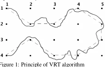
Figure 1: Principle of VRT algorithm
In Figure 1, the black point stands for a RFID reader and the matrix is a RFID Reader Network. As Figure 1 depicted, when a transponder moves from reader (1, 1) to reader (2, 2), the straight line between them is regarded as the track of the transponder by us. Therefore, when moving along the thick curve in the figure, which denotes the real path of a person or object in the RFID Network, the transponder is interrogated by readers along the path. And the virtual line (coined Virtual Route) is defined as the track of the transponder. So the track in Figure 1 is:
Track = Virtual Route = (1,1)(2,2)(2,3)(1,4)(2,5) (3,5)(4,4)(4,3)(3,2)(4,1)
It is noted that, when a reader interrogates one transponder, the next reader interrogating it along the track MUST be adjacent to the previous reader. In Figure 1, it is obvious that the transponder at (2, 3) cannot jump to (2, 5) directly without activating reader (1, 4), (2, 4) or (3, 4). Hence, the next reader of (2, 3) along the track MUST be one of following readers:
{
(1,2), (1,3), (1,4), (2,2), (2,4), (3,2), (3,3), (3,4)}
Therefore, VRT algorithm MUST choose adjacent readers along the track. If two successive readers along the track are not adjacent to each other, special mechanism will be executed to guarantee that each reader along the track is contiguous to its last and next reader in real-word position. The virtual line connecting readers in Fig. 1 looks like a Route transferring data packets along the nodes. Due to this route is not real we name it “Virtual Route”. In VRT algorithm, we use “Virtual Route” to stand for track of transponder in the RFID Reader Network. And that is why this algorithm is coined Virtual Route Tracking (VRT).
Of course, real-world RFID Reader Network is impossible to place readers so regular (exactly like a Matrix), and Figure 1 here only depicts fundamental of this algorithm theoretically.
2.2 Definition of Tracking Vector
More important, the concept of Tracking Vector (TV) is proposed here. Tracking vector plays a key role in collecting tracking information and calculating the track. We define the combination of the transponder identity, the interrogation time and the identifier of reader as Tracking Vector. The structure of TV is:
<Ti, tj, Rk> = < Tag i, timestamp j, Reader k >
Here, the tag identity is a global unique number stored in the electronic chip of each tag and interrogated by reader. VRT algorithm can simultaneously track tens, even hundreds of tags tagged on objects or persons within a single network by classifying different tags according to the unique identity in each Tracking Vector.
Timestamp is the interrogation time of RFID reader when the tag entering its interrogation zone. We assume that all RFID readers in RFID Reader Network are synchronous. And only one tracking vector is generated no matter how long a tag stays within the interrogation zone of one reader.
The third parameter in tracking vector is the identifier of the reader. VRT algorithm uses the position of readers to track tags. It is noted that successive selected readers are all adjacent to each other and therefore can form a Virtual Route, therefore, reader identifiers of two successive Tracking vectors MUST stand for two contiguous readers in real network.
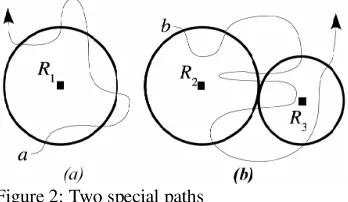
2.3 Two Special Conditions
As Figure 2 shows, when one tag moves along path a, three tracking vectors containing the same reader identifier are generated by reader R1. At this time, VRT algorithm only
chooses the first vector and deletes others.
, ,
,( ), ,
, , ,
,
3 2 1 1 1 1
3
1 2 1
1 T t R t t t
R t T
R t T R t T
x x
x
x
Figure 2: Two special paths
Suppose the tag alternates between two readers, e.g., R2
and R3in Figure 2, only the first two or three tracking vectors
should be remained. The method is specified as follows.
3 vectors of path b in Figure 2 are processed as:
)
3. RESEARCH METHOD
3.1 Research Design
Figure 3 is shown diagram block of the research design. The system constrains traffic light controller (TLC), microcontroller for control management system, RFID readers, RFID tags, personal computer (PC) for database system and sensors of magnetic flux.
Figure 3: Block diagram of the research design.
The architecture of the research method of the RFID-based red light violation detection is shown at Figure 4. The crossroad is quarter section. The RFID readers make an sensor detect straight destination and third sensor is turn right
detection. We assume that Indonesia traffic is turn left go ahead.
3
Figure 4: The architecture of the RFID-based red light violation detection
3.2 Algorithm Detail
The previous papers have been proposed in development of algorithm, for examples are Design of Traffic Light Control Systems Using Statecharts [8], Road Data Input System using Digital Map in Roadtraffic Simulation [9] and The Vehicle Junction Model and its Verification in Traffic Simulation [10] The speed of vehicle pass on crossroad is low until medium speed. In this algorithm, we take the vehicle speed up to 60 km/h or 0.0167 m/ms. If a range of antenna radiation of RFID readers are 10 meters and the time of sampling per RFID reader is 120 ms, so we result 5 samplings.
times
Where, v = vehicle speed (meter/millisecond, m/ms) x = range of antenna radiation (meter, m)
t = time to pass antenna radiation (millisecond, ms) Ts = Time of sampling (ms)
S = number of sampling (time)
The time of sampling is important to determine accuracy of violation detection.
The procedure algorithm is below: 1. Set Structure of Vector Tag ID
2. Choose direction road to check its status lamp 3. Note time-checking
4. If status lamp is green or yellow read ID tags from RFID Reader. Flux status is neglected.
5. Save time-checking, code of RFID Reader and ID tags into temporary memory address.
6. Monitor and track the ID tags, if there are IDs moves to another RFID Reader, delete the IDs from temporary memory address.
8. If flux status is active/enable, read ID tags from RFID Reader and save time-checking, RFID Reader code and ID tags into temporary address of violator candidate. 9. Monitor and track the ID tags in temporary address of
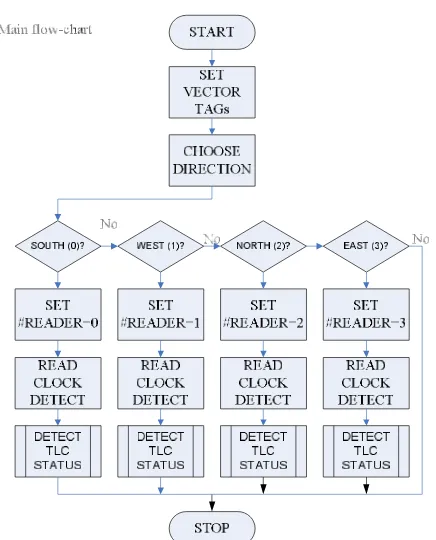
violator candidate to known its movements. If there are IDs moves to another RFID Reader, so the IDs are violator. Save the violator into violator memory address. Figure 5 is shown the flow-chart of this algorithm.
From this algorithm, we hope to result some informations of the ID such as: (1) red light violator; (2) speed prediction of vehicle; and (3) number of vehicle on a capturing.
The vehicle is indicated as violator if on a capturing it is read by Reader as time as sensor of magnetic flux detection. The microcontroller system tracks its ID to monitor movement. If the vehicle ID have not read this Reader and/or read other Reader, so the vehicle is violator.
By assuming that the time of sampling is 120ms and the range of the antenna radiation of Readers is 10 meters, we can prediction speed of vehicle in Table 1. As comparing we take only if the time of sampling is 100ms in Table 2. As Table 1, we see that the time sampling will determine number of sampling. However, smaller number of sampling is very influence in determine speed of vehicle. So we assume that the maximum speed of vehicle passed crossroad is 60km/h.
Table 1: Speed prediction. (a) Ts = 120ms; (b) Ts = 100ms
(a) (b)
Time
(ms) (m/ms) (km/h) 1 120 0.08333 300.00
2 240 0.04167 150.00
3 360 0.02778 100.00
4 480 0.02083 75.00 5 600 0.01667 60.00 6 720 0.01389 50.00 7 840 0.01190 42.86 8 960 0.01042 37.50 9 1080 0.00926 33.33 10 1200 0.00833 30.00 12 1440 0.00694 25.00 14 1680 0.00595 21.43 16 1920 0.00521 18.75 18 2160 0.00463 16.67 20 2400 0.00417 15.00 25 3000 0.00333 12.00 30 3600 0.00278 10.00 35 4200 0.00238 8.57 40 4800 0.00208 7.50 45 5400 0.00185 6.67 50 6000 0.00167 6.00 55 6600 0.00152 5.45 60 7200 0.00139 5.00
Speed Number of
Sampling
Time
(ms) (m/ms) (km/h) 1 100 0.10000 360.00
2 200 0.05000 180.00
3 300 0.03333 120.00
4 400 0.02500 90.00 5 500 0.02000 72.00 6 600 0.01667 60.00 7 700 0.01429 51.43 8 800 0.01250 45.00 9 900 0.01111 40.00 10 1000 0.01000 36.00 12 1200 0.00833 30.00 14 1400 0.00714 25.71 16 1600 0.00625 22.50 18 1800 0.00556 20.00 20 2000 0.00500 18.00 25 2500 0.00400 14.40 30 3000 0.00333 12.00 35 3500 0.00286 10.29 40 4000 0.00250 9.00 45 4500 0.00222 8.00 50 5000 0.00200 7.20 55 5500 0.00182 6.55 60 6000 0.00167 6.00
Speed Number of
Sampling
By referring the range of radiation of the Reader antenna is 10 meters and a minimum length of vehicle is 3.5 meters, so we can count the number of vehicle on a capturing. Figure 6 is shown a vehicle situation on a capture time. The maximum number of vehicle is 13 by a capture time. If the time of sampling, Ts, is 100ms, so the maximum number of vehicle is
130 per second.
Figure 5: The flow-chart of the algorithm for RFID-based red light violation detection
Continuation of Figure 5
Figure 6: Prediction of vehicle number on a capturing
4. DISCUSSION
In this paper, we propose a tracking algorithm for RFID-based red light violation detection. We will do to simulate this use MadLab/Simulink. The database generator is built with the Visual Query Builder (VQB) or Microsoft Office Access.
5. CONCLUSION
By scenario in this proposal, we can take some in
formations: (1) vehicle violator; (2) scalability on
prediction system; (3) detection system of object
on dynamic speed; (4) visibility of system is
independent by solar.
REFERENCES
[1] Http://www.intermec.com, "RFID Overview: Introduction to
Radio Frequency Identification", access date November, 18 2008.
[2] Http://www.paxar.com/, “RFID Basics”, access date
November, 18 2008.
[3] George E. Frangos G.E., “Digital-Based Red Light Running Detection A Building Block Technology for ITS”, http://www.roadtrafffic-technology.com/
contrator/detection/noptel/noptel.pdf, access date Dec, 11
2008.
[4] Http://www.superrfid.net/english/index/, “Automatic vehicle
identification (AVI) and city traffic management system”, access date May, 23 2008.
[5] Chang S.L., Chen L.S., Chung Y.C., Chen S.W., “Automatic License Plate Recognition”, IEEE Transaction on Intelligent Transportation Systems, Vol. 5, No. 1, March 2004, IEEE, 2004.
[6] Suresh K.V., Kumar G.M., Rajagopalan A.N.,
“Superresolution of License Plates in Real Traffic Videos”, IEEE Transaction on Intelligent Tranportation Systems, Vol. 8, No. 2, June 2007., IEEE, 2007.
[7] Jiang W., Yu D., Ma Y., ”A Tracking Algorithm in RFID Reader Network”, Proceeding of the Japan-China Joint Workshop on Frontier of Computer Science and Technology (FCST’06), IEEE, 2006.
[8] Huang Y.S., “Design of Traffic Light Control Systems Using Statecharts”, The Computer Journal, Vol. 49 No. 6, 2006, Published by Oxford University Press on behalf of The British Computer Society, 2006.
[9] Namekawa M., Aoyagi N., Ueda Y. and Satoh A., "Road Data Input System using Digital Map in Roadtraffic Simulation", http://mssanz.org.au/
modsim07/papers/55_s53/RoadDatas53_Namekawa.pdf,
tanggal akses 20 Mei 2009.
Simulation", Proceedings of 2nd International Conference on Asian Simulation and Modeling 2007, (ASIMMOD2007),
Chiang Mai, Thailand.
COPYRIGHT
All papers submitted must be original, unpublished work not under consideration for publication elsewhere. Authors are responsible to obtain all necessary permission for the reproduction of tables, figures and images and must be appropriately acknowledged. The paper is not defamatory; and the paper does not infringe any other rights of any third party.
The authors agree that the Technical Committee’s decision on whether to publish the paper in the Conference’s proceedings shall be final. The authors should not treat any communication from the Technical Committee members who reviewed their work as an undertaking to publish the paper.