ADVANCED REPRESENTATION TECHNOLOGIES APPLIED TO THE TEMPLE OF
NEPTUNE, THE SPHINX AND THE METOPE IN THE ARCHAEOLOGICAL PARK OF
PAESTUM
T. Cardinale a *, R. Valva b, M. Lucarelli c a
PhD Student, Dipartimento delle Culture Europee e del Mediterraneo, Università degli Studi della Basilicata, Via Lazzazera Matera, Italy - ([email protected])
b
Msc Student, Dipartimento delle Culture Europee e del Mediterraneo, Università degli Studi della Basilicata, Via Lazzazera Matera, Italy - ([email protected])
c
Msc Student, Dipartimento delle Culture Europee e del Mediterraneo, Università degli Studi della Basilicata, Via Lazzazera Matera, Italy - ([email protected])
KEY WORDS: Survey, Preservation, 3D Modelling, Historic Heritage, Digital Images
ABSTRACT:
The Summer School of Surveying and 3D modelling in Paestum was an opportunity to explore the use of innovative tools and advanced techniques in the design, implementation and management of surveys of historic and artistic complexes. In general such methods are used specifically for the development and management of vulnerability maps of existing heritage and so for the preventive conservation and valorisation of the built environment. The accurate detection of risk situations and the systematic promotion of highly selected and minimally invasive maintenance practices means that restoration and the efficiency of cycles of intervention can be optimized, with clear benefits from economic and cultural points of view. The group worked on the survey and 3D modelling of the Temple of Neptune, the Sphinx and the Metope of the Archaeological Park in Paestum.
1. INTRODUCTION
1.1 The Site
Paestum is an ancient colony of Magna Graecia founded around 600 BC by the Sybarites. It was initially called Poseidonia, after Poseidon, or Neptune, the God of the sea, to whom the city was dedicated. Between 400 and 273 BC the site was occupied by the Italic population of Lucania.
In 273 BC the city became a Roman colony under the name of Paestum, because it formed an alliance with Pyrrhus, who made war against the Romans in southern Italy and was defeated in the famous battle of Maleventum, later renamed Beneventum. But there is no doubt that the foundation of the city was preceded by the installation of a commercial farm on the left bank and at the mouth of the river Silaros and that the malarial conditions of the soil then induced the primitive settlers to move the town to the east, to a calcareous bench slightly raised from the plain and on the coast, along the banks of another river. The early settlers on the Silaros developed the waterway and the maritime port of the city, and the Temple of Era Argiva, which soon became one of the largest and most revered sanctuaries of Ancient Italy, was built nearby.
The end of the Roman Empire coincided roughly with the end of the city. The decline of Paestum began between the fourth and seventh centuries AD due to the construction of new lines of communication with the East, which isolated the city from the main trade routes, and, following an outbreak of malaria aggravated by the unhealthiness of the territory, the inhabitants gradually abandoned the city.
The rediscovery of Paestum dates back to 1762, when the modern road that still crosses it was built, and the first excavations brought to light the walls, the temples, the sacred way, the amphitheatre, the baths and the homes.
The National Archaeological Museum of Paestum is one of the most important archaeological museums in Southern Italy. It is located within the ancient city and is organized so as to tell, through the exhibits, the history of Paestum.
1.2 Case studies
1.2.1. The Temple of Neptune
The so-called Temple of Neptune , in reality probably dedicated to Apollo or Zeus, is the enormous and strikingly well-preserved temple on the site. It was built in 470 BC and it is one of the three most complete Greek temples in the world. Its pediments and entablature are virtually intact atop. There are fourteen fluted columns down each side, six each across the front and back. The interior is characterized by three areas: the pronaos, the opisthodomos and a cella in the centre divided by two more rows of smaller columns. The prevailing impression when you are there is of a fragile and inexplicable harmony. Perhaps it is due to the art of the architect, who endowed the horizontal lines with an imperceptible convex curve, and slightly inclined towards the interior the flutings of the corner preserved in the National Archaeological Museum of Paestum, on the ground floor in the Greek-Lucanian section, room 3, urban sanctuaries, showcase 18.
1.2.3. The Metope
cycles. Datable around the middle of the sixth century BC, it includes about 40 metopes. The reconstruction presented is the one proposed in 1937 by Paola Zancani Montuoro and Umberto Zanotti Bianco and then perfected by the architect F. Krauss. This reconstruction, which attributed the metopes to a small rectangular building (thesauros), has proved incorrect in the light of the recent attribution to the early decades of the third century BC of the so-called thesauros. The detected metope depicts the killing of Alcyoneus by Heracles.
1.3 Objectives
The goals of the survey and three-dimensional modelling are: - to monitor;
- to record;
- to restore and to preserve the cultural heritage;
- to use critically the tools and the techniques of the discipline whose theories are typical of the photogrammetry and 3D laser scanning;
- to obtain three-dimensional metric models of architectural and archaeological objects through the acquisition and processing of digital images and laser scanning with appropriate software. (Fig.1). It is a non-invasive, low-cost and user-friendly interface that uses photography for the survey and three-dimensional modelling of architectural, cultural and archaeological objects. Compared with active sensors, photogrammetric surveys are based on images that contain all the information, i.e. geometry and textures.
Figure 1. The Temple of Neptune
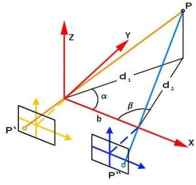
The photogrammetric technique provides metric information on the size, shape and position of an object or scene. This is possible once the geometric relationship between images and real scene is rebuilt using the mathematical model of collinearity and at least two images.
The principles on which this technique is based are the
- reversing the process of projection, the image P ' of the point is projected onto the real point P;
- repeating the experience with two cameras, positioned at a certain distance (which we call the "base"), the rays projecting the images P ' and P'' of the point P intersect at the same point.
Taking advantage of the similarity of triangles determined by the rays projecting the point P, there is a bijective correspondence between the coordinates x, y, z of P in the Cartesian reference and the two pairs of coordinates of the images P ' and P'' in the references fixed on the two frames. The origin of each of the two systems, existing on frames, is located at the point of intersection of the frame with the perpendicular conducted from the center of projection to the surface of the frame itself. This point is called the "main point". It also argues that the coordinates (x, y, z) of the point P are linear functions of the base b (Fig.2).
Therefore, if all other variables remain unchanged, the optical normally used on the ground or mounted on aerial platforms or satellites. There are different types of digital cameras currently on the market. The two main types are divided into "compact" and "SLR", depending on the sensor (CCD or CMOS, matrix or linear), the optics (fixed or interchangeable), the stability, the cost and the use. There are also panoramic cameras able to capture high-resolution spherical images (geometric and radiometric).
Camera calibration and image resolution and amount are crucial for good photogrammetric plotting and data processing. Since the software must be able to easily recognize the homologous points and is based on stereoscopy, the photos were taken at a specific distance from the object (typically a third of the height of the same) and so that the same point appears in at least 3 or 4 images.
2.1.2. The 3D Laser Scanner and the Drone
The survey of the Sphinx (Fig.3) and the Metope (Fig.4) was carried out with the 3D Laser Artec MH / MHT Triangulation-based Scanner. With this tool, the scanning process is extremely easy because you have just to move continuously around the object and you can recover it from various angles, while the software automatically combines all the captured frames in a single mesh. You should also avoid stabling and sudden movements. Thanks to a measurement speed up to 5000 points per second, the instrument quickly performs the acquisition, ensuring a high resolution (up to 0.5 mm) and an optimal accuracy (up to 0.1 mm). The geometric resolution, i.e. the distance between 2 points in the cloud, is of 0.2-0.3 mm. This kind of laser is indicated for objects of average size and allows a significant non-invasive relief. It is preferable not to use this laser scanner with reflective objects because, in the projection of the frames, the triangular grid would be reflected on the surface. For the same reason, the scans must be performed in places with moderate light. So the surface characteristics are critical to the proper instrument operation. Our work is divided into several steps, using the same procedure for both the survey and both the 3D modeling of the sphinx and the metope.
Figure 3. Data acquisition of the Sphinx with Artec MH/MHT
Due to the small field of view of the instrument, in order to have a complete and detailed survey of the object, during the design phase it was necessary to provide a large and sufficient number of scans to cover the entire surface and to obtain an overlap between contiguous range map is around 30-40%. The acquisition of the scans was performed using the 3D Laser Artec MH / MHT Triangulation-based Scanner connected to the PC in real time because this is the only way you can see the individual scans. Twenty-eight scans of the Sphinx and twenty-four of the Metope were made. Each scan is saved as a project to avoid overloading the system. These scans are saved in a project that can contain a maximum of six scans. To cover the entire surface of the object it was necessary to record more than
one project. At this phase we had to be careful to keep a distance of 600-700 mm from the object and have a linear movement in order not to lose the instrument reference coordinates and to obtain scans with as little noise as possible.
Figure 4. Data acquisition of the Metope with Artec MH/MHT
The Zenith drone (weight: 1.3 kg, carbon fiber) was used to make the aerial survey of the Temple of Neptune (Fig.6). The flight was scheduled according to images from Google Maps, in order to have a preventive georeference. The route was realized with a broken line through Why Point. The photographic strips were generated with shots every millisecond. The time available for the flight and the achievement of an altitude between 15 and 300 meters was 20-25 minutes. All data were manipulated by the base station which was mobile and powered by battery. The camera was a compact PENTAX. The telemetry was stored in the drone SD and the images in the machine SD. About 40 photos could be taken. Error is 2.5 mm. The main problems are related to battery life and climatic conditions.
Figure 5. The Trimble Total Station
Figure 6. The Zenith drone
2.2 Data processing
2.2.1. Alignment
For the data processing of the Temple of Neptune we used Agisoft PhotoScan software, which can manage a series of photogrammetric and topographic data. Once photos are loaded into PhotoScan, they need to be aligned. At this stage PhotoScan finds the camera position for each photo and builds a point cloud model (Fig.7).
To align a set of photos the steps are:
1. select Align Photos command from the Workflow menu; 2. in the Align Photos dialog box select the desired alignment options. The progress dialog box will appear displaying the current processing status.
Once that alignment has been completed, the computer camera positions and a sparse point cloud will be displayed (Fig.8). The point cloud and estimated camera positions can be exported for processing with another software if needed.
Incorrectly positioned photos can be realigned in this way: 1. reset alignment for incorrectly positioned photos using Reset Photo Alignment command from the photo context menu; 2. select photos to be realigned and use Align Selected Photos command from the photo context menu;
3. the progress dialog box will appear displaying the current processing status.
Figure 7. The point cloud in the model of the Temple of Neptune
Figure 8. The position of the photos in the model of the column
There are certain parameters that control the photo alignment procedure and can be modified in the Align Photos dialog box. These are: accuracy (higher accuracy setting helps to obtain more accurate camera position estimates); pair preselection (image pair preselection option may speed up the long-time process due to selection of a subset of image pairs to be matched); constrain features by mask; building model geometry.
2.2.2. 3D modelling
3D model reconstruction is a computationally intensive operation and can take a long time, depending on the quantity and resolution of loaded photos. It is advisable to build a model with the lowest quality first to estimate the applicability of the chosen reconstruction method, and then to recompute the results using a higher quality setting. It is also a good idea to save the project before building the geometry.
PhotoScan supports several reconstruction methods and settings, which help to produce optimal reconstructions for a given data set. In this case, for the object type, we choose the arbitrary one, because it can be used for modeling of any kind of closed object, such as statues, buildings, etc. In other cases you can use the height field object type, which is optimized for modeling of planar surfaces, such as terrains or basreliefs. This should be selected for aerial photography processing as it requires less memory and allows for larger data set processing. As regards geometry type the choice is between sharp and smooth geometry. The sharp geometry type option leads to more accurate reconstruction results and does not introduce extra geometry, like hole-filling "patches". The smooth geometry type option produces watertight reconstructions with no or little holes on the resulting surface. Large areas of extra geometry might be generated with this method, but they could be easily removed later using selection and cropping tools. In the end we generated the 3D model texture by the selection of the desired texture generation parameters in the Build Texture dialog box.
The last step is exporting results: point clouds and camera calibration data can be exported right after photo alignment is completed. All other export options are available after the geometry is built.
Figure 9. ICP for the Metope scans alignment
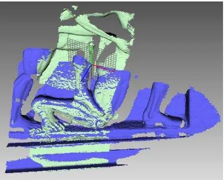
The approach we used for the Metope (Fig.9) and the Sphinx (Fig.10) scans alignment is the method of Interactive Closest Point (ICP), which provides a first phase of rough alignment of pairs of scans identifying three or four homologous points, and a phase of fine alignment in which all scans have to be united starting from a reference one. For the first phase we used the software provided by Artec, then we switched to a software known as Geomagic Studio, because Artec Studio is not able to handle large file extension. On the basis of the common areas the scans are aligned to the previous ones and then exported to proceed with the optimization phase (Fig.11).
Figure 10. Identification of the homologous points
Figure 11. Overlapping scans in Artec Studio
2.3 Optimization
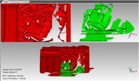
Once these steps are completed you can proceed in the model optimization, through a series of steps: cleaning in order to delete all typological inconsistencies in the mesh and to remove not connected triangles (manually: through the use of selection tools; automatically: through the use of filtering tools, as mesh-doctor, in order to achieve a better correction of the imperfections); recording: manual registration: it allows the user to create a rough recording of two or more overlapping scans, defining the corresponding points in the overlapping regions and reducing the number of triangles, without altering the detail of the surface (Fig.12); global registration: defines the registration of two or more polygon or point objects recorded in an approximate way and it is useful for the filling of small missing surfaces (Fig.13); orientation (through the creation of a plan and alignment of it in the coordinate system).
Figure 12. Manual registration in Geomagic Studio
Figure 13. Global registration in Geomagic Studio
2.3.1. Texturing
The scans provided by the laser scanner are without texture. During the survey we took pictures with a Nikon D3100 to make the model more realistic, so it was necessary to integrate all the techniques. The photos were cleared from the background and, using the Geomagic Studio software, they were projected onto the objects by identifying a minimum of ten homologous points (Fig.14).
The texture and 3D painting (projecting a 2D image on a polygon object resulting in color-mapped textures) allow the restitution of all necessary materials for an accurate metric documentation.
Figure 14. Texture mapping in Geomagic Studio
2.3.2. Creation of 3D model in PDF3D file format
Once the model was complete, our aim was to be able to visualize it quickly and easily. The Geomagic Studio software proved to be the most appropriate means. Saving the model as .obj and exporting it to Adobe Photoshop you can make small changes to the editing of spherical images and you can create 3D pdf files on which you can perform measurements, sections, etc. by activating a instruments series.
A 3D model is initially displayed as a preview two-dimensional picture. Clicking on the 3D model with the Hand tool or the Select tool the model is activated and the 3D toolbar is opened. In this way you can visualize and interact with 3D content of high quality. For example, you can hide and show parts of a 3D model, remove a cover to view the inside of an object and flip the pieces as if they were in your own hands (Fig.15).
Figure 15. 3D model in PDF3D file format
3. RESULTS AND DISCUSSION/CONCLUSIONS
During the acquisition and the processing we may temporarily experience a number of problems due to the models orientation, high processing time, high performance required to the computer, homologous points identification and high noise. The results quality depends on work times, on management costs and on the operator experience. It should therefore be an overall improvement of the knowledge and a continuous updating and also the provision of suitable tools and machines.
Figure 16. 3D model of the Temple of Neptune
Figure 17. 3D model of the column in the reference grid
Figure 18. 3D model of the cell entrance
Figure 19. 3D model of the Metope
4. REFERENCES
Barba S., Fiorillo F., Ortiz Coder P., D'Auria S., De Feo E., 2011. An application for cultural heritage in erasmus placement. Surveys and 3d cataloguing archaeological finds in Merida (Spain). In: The International Archives of the Photogrammetry, Remote sensing and Spatial information Sciences. Vol. XXXVIII-5/W16. Pag.1-6
Bixio A., 2010. Il disegno grafico. Dalla rappresentazione Raster al disegno del Logotipo. Edizioni CUES, Salerno. Fiorillo F., Remondino F., Fernández-Palacios B., Barba S., 2012. 3D Surveying and Modelling of the Archaeological Area of Paestum, Italy. In the: III Internacional de Arqueología, Informática Gráfica, Patrimonio e Innovación.
Guidano G., 2012. Il disegno architettonico fra geometria e fantasia. Alinea, Firenze.
Guidano G., Cerotto P., Conte A., Tolla E., 1991. Disegno. Teoria e applicazioni. Edizioni Ermes, Potenza.
Guidi G., Russo M., Beraldin J., 2010. Acquisizione 3D e modellazione poligonale. McGraw-Hill, Milano.
Kraus K., 2004. Photogrammetry. Geometry from Images and Laser Scan. De Gruyter, Berlin.
Migliari R., 2000. Fondamenti della rappresentazione geometrica e informatica dell’architettura. Edizioni K, Roma.
Mikhail M. et al, 2001. Introduction to Modern Photogrammetry. Wiley, USA.
Remondino, F., 2011. Heritage Recording and 3D Modeling with Photogrammetry and 3D Scanning. In the: Remote Sensing, Vol. 3(6), pp. 1104-1138.
5. ACKNOWLEDGEMENTS
Special thanks to all the staff of the Summer School of Surveying and 3D modelling in Paestum, especially to Fabio Remondino, Salvatore Barba, Antonio Bixio, Fausta Fiorillo, Francesco Fassi and Belen Jiménez Fernández-Palacios.