ACCURACY ESTIMATION OF THE OPTICAL FLOW METHODS IN THE IRIS
STRUCTURE MOTION ANALYSIS VIA CONTROLLED DEFORMATIONS
V. V. Chigrinskiya, I. A. Matveevb
a
Moscow Institute of Physics and Technology, 9 Institutsky per., Dolgoprudny, Moscow, Russia - [email protected] b
Federal Research Center ”Computer Science and Control” of RAS, 44/2 Vavilova st., Moscow, Russia - [email protected]
Commission II, WG II/10
KEY WORDS:Biometrics, Iris Structure, Computer Vision, Image Analysis, Optical Flow, Horn-Schunck Method, Lucas-Kanade Method, Accuracy Estimation
ABSTRACT:
The iris structure motion is analyzed. Extension and compression of the iris structural elements are nonlinear with respect to the pupil radius change. To reveal this nonlinearity the Lucas-Kanade, Horn-Schunck and modified Horn-Chunck optical flow methods are used. To aim is to estimate the accuracies of these methods. To solve the problem an implementation of the methods on the synthetic data is proposed. The data are obtained by applying deformations, which correspond to the certain models, to the eye images. The results of the methods implementation are compared with the used models and the accuracies are estimated on the basis of this comparison. The dataset of N eye images is used to generate the synthetic videos.
1. INTRODUCTION
Iris recognition is a method of biometric human identification that uses mathematical pattern-recognition techniques on video im-ages of one or both of the irises of an individual’s eyes, whose complex patterns are unique. But these patterns change with pupil radius variation and this change is radial non-linear. It means that different images will be obtained by conformal map-ping the same eye’s iris structures with different pupil radiuses into absolutely similar rectangles. The problem is to reveal this non-linearity assuming radial symmetry of the iris structure de-formations and construct the function
f(ρpupil;r) : (0, ρiris)×(0, ρiris]→(0, ρiris], (1)
which maps iris structure of any eye with pupil radius equalsρpupil
into the same eye with pupil radius equalsρiris/2, whereρirisis
the iris radius andris the radius of any structural element of the iris.
To solve the problem optical flow method is proposed. Firstly, videosequence of a human eye response to a flash is obtained by a special device — pupillometer. Frames of this video are images of the same eye with different iris radiuses. After that, frames are preprocessed for a correct optical flows calculation. Obtained optical flows are velocity vector fields which describe movement of any structural element of the iris. The desired function (1) is constructed based on radial components of the optical flows’ vectors.
2. DATA PREPARATION
This paper presents an implementation of the optical flow method on the artificially prepared data — controlled eye deformations. Single eye image is taken as a basis and the videosequence is obtained by pupil radius variation and resulting iris structure de-formation. This deformation is carried out in accordance with preselected certain model. Different models may be used in this
task. For greater similarity with real data normally distributed noise may be added to the images.
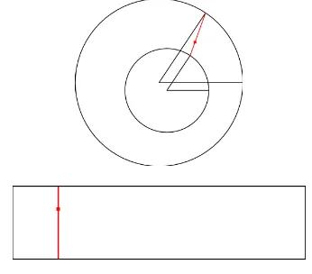
First of all, an iris area is cutted from the photo and mapped into a rectangle of a fixed size by the following rule:
P(m, n) =I(ξ, η), (2)
ξ= (1−λ)(ξpupil+ρpupilcosϕ) +λ(ξiris+ρiriscosϕ),
η= (1−λ)(ηpupil+ρpupilsinϕ) +λ(ηiris+ρirissinϕ),
λ= m
M, ϕ= 2π n N,
whereξpupil, ηpupil— center of the pupil in the origin imageI;
ρpupil— pupil radius;ξiris, ηiris— center of the iris in the origin
imageI;ρiris— iris radius;M, N— size of the result imageP.
Demonstration of the polar transform (2) is shown in the Figure 1.
Ifξ, ηare non-integer, bilinear interpolation is used: I(ξ, η) = (1− {ξ})(1− {η})I([ξ] + 1,[η] + 1)+
+{ξ}(1− {η})I([ξ],[η] + 1)+ +(1− {ξ}){η}I([ξ] + 1,[η])+
+{ξ}{η}I([ξ],[η]) (3)
Let assume that the imagePhas size1×2π. Radially symmetric deformation of the image is it’s compression and extension along a radial axis. It can be described by mapping
d: (0,+∞)×[0,1]→[0,1] (4)
with fixed ends
d(·,0) = 0, d(·,1) = 1. (5)
Also this mapping should be strictly monotonous:
a < b⇔d(·, a)< d(·, b) (6) and should depend on pupil radius. The first argument is ratio of the result and initial pupil radiuses and the second one is polar-axis coordinate. Polar pattern of the eye image with certain pupil radius is obtained by applying to the initial patternPdeformation corresponding to this pupil radius.
Examples of the mapping are given in the Figure 2
0.0 0.2 0.4 0.6 0.8 1.0
Figure 2. Controlled deformation examples
Firstly, iris patternP is obtained from the eye imageIfollowing the (2). Then pupillogram (dependance of pupil radius on frame) is generated. Then iris patterns, corresponding to the pupil ra-diuses from pupilogram, is obtained with the chosen model of controlled deformations. Normally distributed noize with zero mean can be added to the iris patterns. Finally all patterns are transformed to the eye images with pre-selected pupil and iris centers and synthetic data is generated. Pupil area is filled with black and external area is filled with white.
3. PREPROCESSING
Synthetic data is a videosequence of iris structure deformation with pupil radius changing. To find out how accurate is optical flow method in this case, it’s necessary to implement it on the given data and compare its results with expected. The expected optical flow between two frames can be calculated according to the following:
δ(ρ1, ρ2, x) =d(ρ2/ρ1, x)−x, (7)
whereρ1, ρ2— pupil radiuses corresponding to the frames.
After calculating optical floww = (u, v)T between the same
frames, its radial component uis meaned along the tangential axis andL2distance between the obtained and expected optical
flows is calculated:
qρ= Z 1
0
(δ(ρ1, ρ2, x)−Eu(x))2dx. (8)
Standard deviation of the tangential component of the optical flow is also taken into account:
qϕ=Dv=E(v−Ev)2 (9)
For correct performing of the optical flow methods videosequence must be preprocessed. First of all, eye areas of all images must be matched. To do this, every image is centered by iris center, scaled and cropped. Then all frames are linearly mapped to the eye pattern with fixed pupil radiusρpupil =ρiris/2. To enhance
contrast histogram equalization (Acharya and Ray, 2005) of the iris area is implemented.
Its implementation is shown in Figure 3.
0 50 100 150 200 250 300
Figure 3. Histogram equalization
To reduce noise consequent frames are meaned.
It is shown in Figure 4.
Figure 4. Denoising
preprocessed synthetic data is obtained and optical flow can be implemented.
Example of the preprocessed iris area pattern is shown in Fig-ure 5.
Figure 5. Iris area pattern
4. OPTICAL FLOWS
4.1 Lucas-Kanade
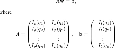
Lucas-Kanade method assumes that the displacement of the im-age contents between two nearby instants (frames) is small and approximately constant within a neighborhood of the pointp un-der consiun-deration. Thus the optical flow equation can be assumed to hold for all pixels within a window centered atp. Namely, the local image flow (velocity) vectorw= (u, v)Tmust satisfy the
following system of linear equations:
Aw=b, (10)
are the partial derivatives of the imageIwith respect to polar co-ordinatesr,ϕand timet.
This system has more equations than unknowns and thus it is usu-ally over-determined. The LucasKanade method obtains a com-promise solution by the least squares principle. Namely, it solves the2×2system:
ATAw=ATb,
instead of (10), so velocity vector is obtained according to the following rule:
w=
ATA−1ATb.
More precisely Lucas-Kanade method is described in (Lucas and Kanade, 1981).
4.2 Horn-Schunck
Horn-Schunck algorithm assumes smoothness in the flow over the whole image. Thus, it tries to minimize distortions in flow
and prefers solutions which show more smoothness. The flow is formulated as a global energy functional which is then sought to be minimized. This function is given for two-dimensional image streams as whereIr, IϕandItare the derivatives of the image intensity val-ues along the radial, tangential and time dimensions respectively,
w = (u, v)T is the optical flow vector, and the parameterαis
a regularization constant. Larger values ofαlead to a smoother flow. This functional can be minimized by solving the associated multi-dimensional Euler-Lagrange equations:
whereLis the integrand of the energe expression (11): L= (Iρu+Iϕv+It)2+α2 k∇uk2+k∇vk2
. (13)
After substitution (13) into (12) following system of differential equations is obtained:
∂ϕ2 denotes the Laplace operator. In
prac-tice the Laplacian is approximated numerically using finite dif-ferences, and may be written
∆u(ρ, ϕ) =u(ρ, ϕ)−u(ρ, ϕ), (15)
whereu(ρ, ϕ)is a weighted average ofucalculated in a neigh-borhood around the pixel at location(ρ, ϕ). Using this notation the above equation system may be written
(
Solving this system with the numerical methods gives iterative procedure
More precisely Horn-Schunck method is described in (Horn and Schunck, 1981).
4.3 Modified Horn-Schunck
In the particular case of this problem it is reasonably to add the regularizer of an eye radial symmetryβ2v2
to the integrandL, so:
L= (Iρu+Iϕv+It)2+α2 k∇uk2+k∇vk2 +β2v2.
After substitution (19) into (12) following system is obtained:
(
Iρ(Iρu+Iϕv+It)−α2∆u= 0,
Iϕ(Iρu+Iϕv+It) +β2v−α2∆v= 0. (20)
Using (15) above system may be written
( (I2
ρ+α2)u+IρIϕv=α2u−IρIt, IρIϕu+ (I2
ϕ+α2+β2)v=α2v−IϕIt,
(21)
and solving this system with numerical methods gives optical floww= (u, v)T
5. COMPUTATIONAL APPROACH
First of all, the initial eye image is taken and iris area is mapped into rectangle. This procedure is shown in Figure 6.
Figure 6. Iris pattern of the initial image
Then adequate pupillogram should be generated. In this case, pupillogram from real data was taken and smoothed. It is shown in Figure 7.
0 50 100 150 200 250
Frame number 0.47
0.48 0.49 0.50 0.51 0.52 0.53 0.54 0.55
Pupil and iris radiuses ratio
Figure 7. Pupillogram
Each frame of the synthetic videosequence are obtained by defor-mation of the initial one with the following rule:
d(ρ2/ρ1, x) =xρ1/ρ2, x∈[0,1]. (22)
It corresponds to the model shown in Figure 8. Consequently,
0.0 0.2 0.4 0.6 0.8 1.0 0.0
0.2 0.4 0.6 0.8 1.0
Figure 8. Deformation model
expected optical flow is
uexpected(n, x) =xρ1/ρn−xρ1/ρn−1, (23)
wherenis a frame number,xis a radial coordinate.
After generating sequence of patterns, normally-distributed noise with zero mean may be added (standard deviation of noise will be a parameter). Then all iris patterns are mapped back into an eye form and procedure of optical flow calculation may be im-plemented. The result of implementation of the Horn-Schunck method withα= 1000in first two frames is shown in Figure 9.
Figure 9. Example of the optical flow calculation
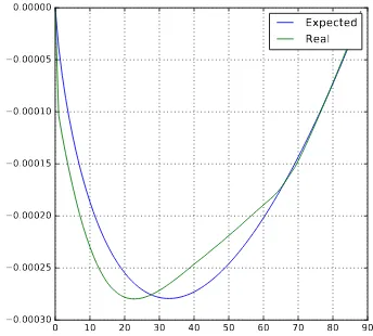
Comparison of real and expected optical flow radial component is shown in Figure 10.
0 10 20 30 40 50 60 70 80 90 −0.00030
−0.00025 −0.00020 −0.00015 −0.00010 −0.00005 0.00000
Expected Real
REFERENCES
Acharya, T. and Ray, A. K., 2005.Image Processing: Principles and Applications. A John Wiley and Sons, Inc., NJ.
Horn, B. K. P. and Schunck, B. G., 1981. Determining optical flow.Artificial Intelligence17, pp. 185–203.