SECOND EDITION
Network Warrior
Gary A. Donahue
Network Warrior, Second Edition by Gary A. Donahue
Copyright © 2011 Gary Donahue. All rights reserved. Printed in the United States of America.
Published by O’Reilly Media, Inc., 1005 Gravenstein Highway North, Sebastopol, CA 95472. O’Reilly books may be purchased for educational, business, or sales promotional use. Online editions are also available for most titles (http://my.safaribooksonline.com). For more information, contact our corporate/institutional sales department: (800) 998-9938 or [email protected].
Editor: Mike Loukides
Production Editor: Adam Zaremba
Copyeditor: Amy Thomson
Proofreader: Rachel Monaghan
Production Services: Molly Sharp
Indexer: Lucie Haskins
Cover Designer: Karen Montgomery
Interior Designer: David Futato
Illustrator: Robert Romano
Printing History:
June 2007: First Edition.
May 2011: Second Edition.
Nutshell Handbook, the Nutshell Handbook logo, and the O’Reilly logo are registered trademarks of O’Reilly Media, Inc. Network Warrior, the image of a German boarhound, and related trade dress are trademarks of O’Reilly Media, Inc.
Many of the designations used by manufacturers and sellers to distinguish their products are claimed as trademarks. Where those designations appear in this book, and O’Reilly Media, Inc. was aware of a trademark claim, the designations have been printed in caps or initial caps.
While every precaution has been taken in the preparation of this book, the publisher and author assume no responsibility for errors or omissions, or for damages resulting from the use of the information con-tained herein.
Table of Contents
Preface . . . xvii
1. What Is a Network? . . . 1
2. Hubs and Switches . . . 5
Hubs 5
Switches 10
Switch Types 14
Planning a Chassis-Based Switch Installation 16
3. Autonegotiation . . . 19
What Is Autonegotiation? 19
How Autonegotiation Works 20
When Autonegotiation Fails 21
Autonegotiation Best Practices 23
Configuring Autonegotiation 23
4. VLANs . . . 25
Connecting VLANs 25
Configuring VLANs 29
CatOS 29
IOS Using VLAN Database 31
IOS Using Global Commands 33
Nexus and NX-OS 35
5. Trunking . . . 37
How Trunks Work 38
ISL 39
802.1Q 39
Which Protocol to Use 40
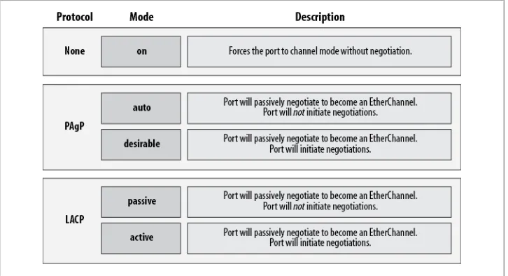
Trunk Negotiation 40
Configuring Trunks 42
IOS 42
CatOS 44
Nexus and NX-OS 46
6. VLAN Trunking Protocol . . . 49
VTP Pruning 52
Dangers of VTP 54
Configuring VTP 55
VTP Domains 55
VTP Mode 56
VTP Password 57
VTP Pruning 58
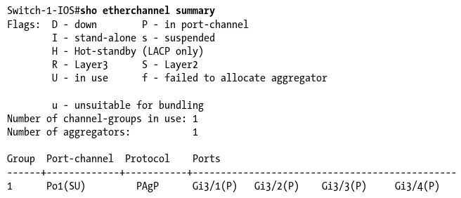
7. Link Aggregation . . . 63
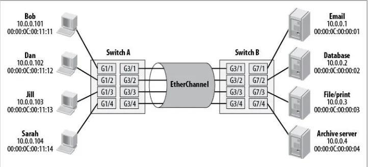
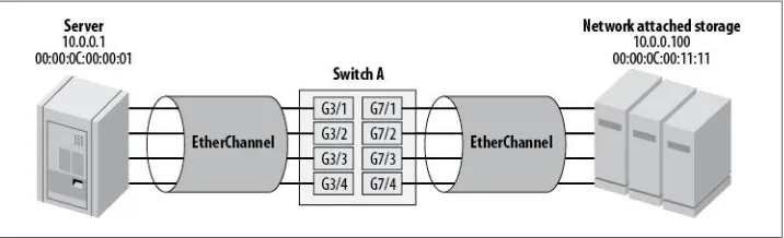
EtherChannel 63
EtherChannel Load Balancing 64
Configuring and Managing EtherChannel 68
Cross-Stack EtherChannel 75
Multichassis EtherChannel (MEC) 75
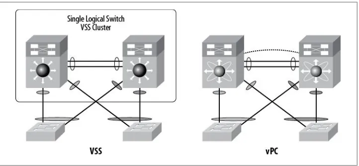
Virtual Port Channel 75
Initial vPC Configuration 76
Adding a vPC 77
8. Spanning Tree . . . 81
Broadcast Storms 82
MAC Address Table Instability 86
Preventing Loops with Spanning Tree 88
How Spanning Tree Works 88
Managing Spanning Tree 91
Additional Spanning Tree Features 95
PortFast 95
BPDU Guard 96
UplinkFast 97
BackboneFast 99
Common Spanning Tree Problems 100
Duplex Mismatch 100
Unidirectional Links 101
Bridge Assurance 103
Designing to Prevent Spanning Tree Problems 104
Use Routing Instead of Switching for Redundancy 104
9. Routing and Routers . . . 105
Routing Tables 106
Route Types 109
The IP Routing Table 109
Host Route 111
Subnet 112
Summary (Group of Subnets) 112
Major Network 113
Supernet (Group of Major Networks) 114
Default Route 114
Virtual Routing and Forwarding 115
10. Routing Protocols . . . 119
Communication Between Routers 120
Metrics and Protocol Types 123
Administrative Distance 125
Specific Routing Protocols 127
RIP 129
RIPv2 132
EIGRP 133
OSPF 137
BGP 143
11. Redistribution . . . 147
Redistributing into RIP 149
Redistributing into EIGRP 152
Redistributing into OSPF 154
Mutual Redistribution 156
Redistribution Loops 157
Limiting Redistribution 159
Route Tags 159
A Real-World Example 163
12. Tunnels . . . 167
GRE Tunnels 168
GRE Tunnels and Routing Protocols 173
GRE and Access Lists 178
13. First Hop Redundancy . . . 181
HSRP 181
HSRP Interface Tracking 184
When HSRP Isn’t Enough 186
Nexus and HSRP 189
GLBP 189
Object Tracking in GLBP 194
14. Route Maps . . . 197
Building a Route Map 198
Policy Routing Example 200
Monitoring Policy Routing 203
15. Switching Algorithms in Cisco Routers . . . 207
Process Switching 209
Interrupt Context Switching 210
Fast Switching 211
Optimum Switching 213
CEF 213
Configuring and Managing Switching Paths 216
Process Switching 216
Fast Switching 218
CEF 219
16. Multilayer Switches . . . 221
Configuring SVIs 223
IOS (4500, 6500, 3550, 3750, etc.) 223
Hybrid Mode (4500, 6500) 225
NX-OS (Nexus 7000, 5000) 227
Multilayer Switch Models 228
17. Cisco 6500 Multilayer Switches . . . 231
Architecture 233
Buses 234
Enhanced Chassis 237
Vertical Enhanced Chassis 238
Supervisors 238
Modules 240
CatOS Versus IOS 249
Installing VSS 253
Other Recommended VSS Commands 259
VSS Failover Commands 261
Miscellaneous VSS Commands 262
VSS Best Practices 263
18. Cisco Nexus . . . 265
Nexus 7000 266
Nexus 5000 268
Nexus 2000 270
Nexus 1000 Series 272
NX-OS 273
NX-OS Versus IOS 274
Nexus Iconography 279
Nexus Design Features 280
Virtual Routing and Forwarding 281
Virtual Device Contexts 283
Shared and Dedicated Rate-Mode 287
Configuring Fabric Extenders (FEXs) 290
Virtual Port Channel 294
Config-Sync 300
Configuration Rollback 309
Upgrading NX-OS 312
19. Catalyst 3750 Features . . . 317
Stacking 317
Interface Ranges 319
Macros 320
Flex Links 324
Storm Control 325
Port Security 329
SPAN 332
Voice VLAN 336
QoS 338
20. Telecom Nomenclature . . . 341
Telecom Glossary 342
21. T1 . . . 355
Understanding T1 Duplex 355
Types of T1 356
Encoding 357
AMI 357
B8ZS 358
Framing 359
D4/Superframe 360
Extended Super Frame 360
Performance Monitoring 362
Loss of Signal 362
Out of Frame 362
Bipolar Violation 362
CRC6 363
Errored Seconds 363
Extreme Errored Seconds 363
Alarms 363
Red Alarm 364
Yellow Alarm 364
Blue Alarm 366
Troubleshooting T1s 366
Loopback Tests 366
Integrated CSU/DSUs 369
Configuring T1s 370
CSU/DSU Configuration 370
CSU/DSU Troubleshooting 371
22. DS3 . . . 375
Framing 375
M13 376
C-Bits 377
Clear-Channel DS3 Framing 378
Line Coding 379
Configuring DS3s 379
Clear-Channel DS3 379
Channelized DS3 381
23. Frame Relay . . . 387
Ordering Frame Relay Service 390
Frame Relay Network Design 391
Oversubscription 393
Local Management Interface 394
Congestion Avoidance in Frame Relay 395
Configuring Frame Relay 396
Basic Frame Relay with Two Nodes 396
Basic Frame Relay with More Than Two Nodes 398
Frame Relay Subinterfaces 401
Troubleshooting Frame Relay 403
24. MPLS . . . 409
25. Access Lists . . . 415
Designing Access Lists 415
Named Versus Numbered 415
Where to Apply Access Lists 417
Naming Access Lists 418
Top-Down Processing 419
Most-Used on Top 419
Using Groups in ASA and PIX ACLs 421
Deleting ACLs 424
Turbo ACLs 424
Allowing Outbound Traceroute and Ping 425
Allowing MTU Path Discovery Packets 426
ACLs in Multilayer Switches 427
Configuring Port ACLs 427
Configuring Router ACLs 428
Configuring VLAN Maps 429
Reflexive Access Lists 431
Configuring Reflexive Access Lists 433
26. Authentication in Cisco Devices . . . 437
Basic (Non-AAA) Authentication 437
Line Passwords 437
Configuring Local Users 439
PPP Authentication 442
AAA Authentication 449
Enabling AAA 449
Configuring Security Server Information 450
Creating Method Lists 453
Applying Method Lists 456
27. Basic Firewall Theory . . . 459
Best Practices 459
The DMZ 461
Another DMZ Example 463
Multiple DMZ Example 464
Alternate Designs 465
28. ASA Firewall Configuration . . . 469
Contexts 470
Interfaces and Security Levels 470
Names 473
Object Groups 475
Inspects 477
Managing Contexts 479
Context Types 480
The Classifier 482
Configuring Contexts 486
Interfaces and Contexts 489
Write Mem Behavior 489
Failover 490
Failover Terminology 491
Understanding Failover 492
Configuring Failover—Active/Standby 494
Monitoring Failover 496
Configuring Failover—Active/Active 497
NAT 501
NAT Commands 502
NAT Examples 502
Miscellaneous 506
Remote Access 506
Saving Configuration Changes 506
Logging 507
Troubleshooting 509
29. Wireless . . . 511
Wireless Standards 511
Security 513
Configuring a WAP 516
MAC Address Filtering 520
Troubleshooting 521
30. VoIP . . . 523
How VoIP Works 523
Protocols 525
Telephony Terms 527
Cisco Telephony Terms 528
Common Issues with VoIP 530
Small-Office VoIP Example 532
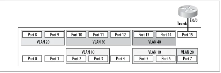
VLANs 533
Switch Ports 535
QoS on the CME Router 536
DHCP for Phones 537
TFTP Service 537
Telephony Service 538
Dial Plan 542
Voice Ports 542
Configuring Phones 543
Dial Peers 551
Troubleshooting 567
Phone Registration 567
TFTP 568
Dial Peer 569
SIP 570
31. Introduction to QoS . . . 573
Types of QoS 577
QoS Mechanics 578
Priorities 578
Flavors of QoS 581
Common QoS Misconceptions 586
QoS “Carves Up” a Link into Smaller Logical Links 586
QoS Limits Bandwidth 587
QoS Resolves a Need for More Bandwidth 587
QoS Prevents Packets from Being Dropped 588
QoS Will Make You More Attractive to the Opposite Sex 588
32. Designing QoS . . . 589
LLQ Scenario 589
Protocols 589
Priorities 590
Determine Bandwidth Requirements 592
Configuring the Routers 594
Class Maps 594
Policy Maps 596
Service Policies 597
Traffic-Shaping Scenarios 598
Scenario 1: Ethernet Handoff 598
Scenario 2: Frame Relay Speed Mismatch 602
33. The Congested Network . . . 607
Determining Whether the Network Is Congested 607
Resolving the Problem 612
34. The Converged Network . . . 615
Configuration 615
Monitoring QoS 617
Troubleshooting a Converged Network 620
Incorrect Queue Configuration 620
Priority Queue Too Small 621
Priority Queue Too Large 623
Nonpriority Queue Too Small 624
Nonpriority Queue Too Large 624
Default Queue Too Small 626
Default Queue Too Large 626
35. Designing Networks . . . 627
Documentation 627
Requirements Documents 628
Port Layout Spreadsheets 629
IP and VLAN Spreadsheets 633
Bay Face Layouts 634
Power and Cooling Requirements 634
Tips for Network Diagrams 636
Naming Conventions for Devices 637
Network Designs 639
Corporate Networks 639
Ecommerce Websites 643
Modern Virtual Server Environments 648
Small Networks 648
36. IP Design . . . 649
Public Versus Private IP Space 649
VLSM 652
CIDR 654
Allocating IP Network Space 656
Allocating IP Subnets 658
Sequential 658
Divide by Half 660
Reverse Binary 660
IP Subnetting Made Easy 663
37. IPv6 . . . 671
Addressing 673
Subnet Masks 675
Address Types 675
Subnetting 677
NAT 678
Simple Router Configuration 679
38. Network Time Protocol . . . 689
What Is Accurate Time? 689
NTP Design 691
Configuring NTP 693
NTP Server 696
39. Failures . . . 697
Human Error 697
Multiple Component Failure 698
Disaster Chains 699
No Failover Testing 700
Troubleshooting 700
Remain Calm 701
Log Your Actions 701
Find Out What Changed 701
Check the Physical Layer First! 702
Assume Nothing; Prove Everything 702
Isolate the Problem 703
Don’t Look for Zebras 703
Do a Physical Audit 703
Escalate 704
Troubleshooting in a Team Environment 704
The Janitor Principle 704
40. GAD’s Maxims . . . 705
Maxim #1 705
Politics 706
Money 707
The Right Way to Do It 707
Maxim #2 708
Simplify 709
Standardize 709
Stabilize 709
Maxim #3 709
Lower Costs 710
Increase Performance or Capacity 711
Increase Reliability 712
41. Avoiding Frustration . . . 715
Why Everything Is Messed Up 715
How to Sell Your Ideas to Management 718
When to Upgrade and Why 722
The Dangers of Upgrading 723
Valid Reasons to Upgrade 724
Why Change Control Is Your Friend 725
How Not to Be a Computer Jerk 727
Behavioral 727
Environmental 729
Leadership and Mentoring 730
Preface
The examples used in this book are taken from my own experiences, as well as from the experiences of those with or for whom I have had the pleasure of working. Of course, for obvious legal and honorable reasons, the exact details and any information that might reveal the identities of the other parties involved have been changed.
Cisco equipment is used for the examples within this book and, with very few excep-tions, the examples are TCP/IP-based. You may argue that a book of this type should include examples using different protocols and equipment from a variety of vendors, and, to a degree, that argument is valid. However, a book that aims to cover the breadth of technologies contained herein, while also attempting to show examples of these technologies from the point of view of different vendors, would be quite an impractical size. The fact is that Cisco Systems (much to the chagrin of its competitors, I’m sure) is the premier player in the networking arena. Likewise, TCP/IP is the protocol of the Internet, and the protocol used by most networked devices. Is it the best protocol for the job? Perhaps not, but it is the protocol in use today, so it’s what I’ve used in all my examples. Not long ago, the Cisco CCIE exam still included Token Ring Source Route Bridging, AppleTalk, and IPX. Those days are gone, however, indicating that even Cisco understands that TCP/IP is where everyone is heading. I have included a chapter on IPv6 in this edition, since it looks like we’re heading that way eventually.
WAN technology can include everything from dial-up modems (which, thankfully, are becoming quite rare) to T1, DS3, SONET, MPLS, and so on. We will look at many of these topics, but we will not delve too deeply into them, for they are the subject of entire books unto themselves—some of which may already sit next to this one on your O’Reilly bookshelf.
Again, all the examples used in this book are drawn from real experiences, most of which I faced myself during my career as a networking engineer, consultant, manager, and director. I have run my own company and have had the pleasure of working with some of the best people in the industry. The solutions presented in these chapters are the ones my teams and I discovered or learned about in the process of resolving the issues we encountered.
I faced a very tough decision when writing the second edition of this book. Should I keep the CatOS commands or discard them in favor of newer Nexus NX-OS examples? This decision was tough not only because my inclusion of CatOS resulted in some praise from my readers, but also because as of this writing in early 2011, I’m still seeing CatOS switches running in large enterprise and ecommerce networks. As such, I decided to keep the CatOS examples and simply add NX-OS commands.
I have added many topics in this book based mostly on feedback from readers. New topics include Cisco Nexus, wireless, MPLS, IPv6, and Voice over IP (VoIP). Some of these topics are covered in depth, and others, such as MPLS, are purposely light for reasons outlined in the chapters. Topics such as Nexus and VoIP are vast and added significantly to the page count of an already large and expensive book. I have also removed the chapters on server load balancing, both because I was never really happy with those chapters and because I could not get my hands on an ACE module or ap-pliance in order to update the examples.
On the subject of examples, I have updated them to reflect newer hardware in every applicable chapter. Where I used 3550 switches in the first edition, I now use 3750s. Where I used PIX firewalls, I now use ASA appliances. I have also included examples from Cisco Nexus switches in every chapter that I felt warranted them. Many chapters therefore have examples from Cat-OS, IOS, and NX-OS. Enjoy them, because I guar-antee that CatOS will not survive into the third edition.
Who Should Read This Book
This book is intended for anyone with first-level certification knowledge of data net-working. Anyone with a CCNA or equivalent (or greater) knowledge should benefit from this book. My goal in writing Network Warrior is to explain complex ideas in an easy-to-understand manner. While the book contains introductions to many topics, you can also consider it a reference for executing common tasks related to those topics. I am a teacher at heart, and this book allows me to teach more people than I’d ever thought possible. I hope you will find the discussions both informative and enjoyable. I have noticed over the years that people in the computer, networking, and telecom industries are often misinformed about the basics of these disciplines. I believe that in many cases, this is the result of poor teaching or the use of reference material that does not convey complex concepts well. With this book, I hope to show people how easy some of these concepts are. Of course, as I like to say, “It’s easy when you know how,” so I have tried very hard to help anyone who picks up my book understand the ideas contained herein.
This book does not explain the OSI stack, but it does briefly explain the differences between hubs, switches, and routers. You will need to have a basic understanding of what Layer 2 means as it relates to the OSI stack. Beyond that, this book tries to cover it all, but not like most other books.
This book attempts to teach you what you need to know in the real world. When should you choose a Layer-3 switch over a Layer-2 switch? How can you tell if your network is performing as it should? How do you fix a broadcast storm? How do you know you’re having one? How do you know you have a spanning tree loop, and how do you fix it? What is a T1, or a DS3 for that matter? How do they work? In this book, you’ll find the answers to all of these questions and many, many more. I tried to fill this book with information that many network engineers seem to get wrong through no fault of their own. Network Warrior includes configuration examples from real-world events and designs, and is littered with anecdotes from my time in the field—I hope you enjoy them.
Conventions Used in This Book
The following typographical conventions are used in this book: Italic
Used for new terms where they are defined, for emphasis, and for URLs Constant width
Used for commands, output from devices as it is seen on the screen, and samples of Request for Comments (RFC) documents reproduced in the text
Constant width italic
Used to indicate arguments within commands for which you should supply values
Constant width bold
Used for commands to be entered by the user and to highlight sections of output from a device that have been referenced in the text or are significant in some way
Indicates a tip, suggestion, or general note
Indicates a warning or caution
Using Code Examples
This book is here to help you get your job done. In general, you may use the code in this book in your programs and documentation. You do not need to contact us for permission unless you’re reproducing a significant portion of the code. For example, writing a program that uses several chunks of code from this book does not require permission. Selling or distributing a CD-ROM of examples from O’Reilly books does require permission. Answering a question by citing this book and quoting example code does not require permission. Incorporating a significant amount of example code from this book into your product’s documentation does require permission.
We appreciate, but do not require, attribution. An attribution usually includes the title, author, publisher, and ISBN. For example: “Network Warrior, Second Edition, by Gary A. Donahue (O’Reilly). Copyright 2011 Gary Donahue, 978-1-449-38786-0.”
If you feel your use of code examples falls outside fair use or the permission given above, feel free to contact us at [email protected].
We’d Like to Hear from You
Please address comments and questions concerning this book to the publisher: O’Reilly Media, Inc.
1005 Gravenstein Highway North Sebastopol, CA 95472
800-998-9938 (in the United States or Canada) 707-829-0515 (international or local)
707-829-0104 (fax)
We have a web page for this book, where we list errata, examples, and any additional information. You can access this page at:
http://www.oreilly.com/catalog/9781449387860
To comment or ask technical questions about this book, send email to: [email protected]
For more information about our books, courses, conferences, and news, see our website at http://www.oreilly.com.
Find us on Facebook: http://facebook.com/oreilly Follow us on Twitter: http://twitter.com/oreillymedia
Safari® Books Online
Safari Books Online is an on-demand digital library that lets you easily search over 7,500 technology and creative reference books and videos to find the answers you need quickly.
With a subscription, you can read any page and watch any video from our library online. Read books on your cell phone and mobile devices. Access new titles before they are available for print, and get exclusive access to manuscripts in development and post feedback for the authors. Copy and paste code samples, organize your favorites, down-load chapters, bookmark key sections, create notes, print out pages, and benefit from tons of other time-saving features.
O’Reilly Media has uploaded this book to the Safari Books Online service. To have full digital access to this book and others on similar topics from O’Reilly and other pub-lishers, sign up for free at http://my.safaribooksonline.com.
Acknowledgments
Writing a book is hard work—far harder than I ever imagined. Though I spent countless hours alone in front of a keyboard, I could not have accomplished the task without the help of many others.
I would like to thank my lovely wife, Lauren, for being patient, loving, and supportive. Lauren, being my in-house proofreader, was also the first line of defense against gram-matical snafus. Many of the chapters no doubt bored her to tears, but I know she enjoyed at least a few. Thank you for helping me achieve this goal in my life.
I would like to thank Meghan and Colleen for trying to understand that when I was writing, I couldn’t play. I hope I’ve helped instill in you a sense of perseverance by completing this book. If not, you can be sure that I’ll use it as an example for the rest of your lives. I love you both “bigger than the universe” bunches.
I would like to thank my mother—because she’s my mom, and because she never gave up on me, always believed in me, and always helped me even when she shouldn’t have (Hi, Mom!).
I would like to thank my father for being tough on me when he needed to be, for teaching me how to think logically, and for making me appreciate the beauty in the details. I have fond memories of the two of us sitting in front of my RadioShack Model III com-puter while we entered basic programs from a magazine. I am where I am today largely because of your influence, direction, and teachings. You made me the man I am today. Thank you, Papa. I miss you.
I would like to thank my Cozy, my faithful Newfoundland dog who was tragically put to sleep in my arms so she would no longer have to suffer the pains of cancer. Her body failed while I was writing the first edition of this book, and if not for her, I probably
would not be published today. Her death caused me great grief, which I assuaged by writing. I miss you my Cozy—may you run pain free at the rainbow bridge until we meet again.
I would like to thank Matt Maslowski for letting me use the equipment in his lab that was lacking in mine, and for helping me with Cisco questions when I wasn’t sure of myself. I can’t think of anyone I would trust more to help me with networking topics. Thanks, buddy.
I would like to thank Jeff Fry, CCIE# 22061, for providing me temporary access to a pair of unconfigured Cisco Nexus 7000 switches. This was a very big deal, and the second edition is much more complete as a result.
I would like to thank Jeff Cartwright for giving me my first exciting job at an ISP and for teaching me damn-near everything I know about telecom. I still remember being taught about one’s density while Jeff drove us down Interstate 80, scribbling waveforms on a pad on his knee while I tried not to be visibly frightened. Thanks also for proof-reading some of my telecom chapters. There is no one I would trust more to do so. I would like to thank Mike Stevens for help with readability and for some of the more colorful memories that have been included in this book. His help with PIX firewalls was instrumental to the completion of the first edition. You should also be thankful that I haven’t included any pictures. I have this one from the Secaucus data center... I would like to thank Peter Martin for helping me with some subjects in the lab for which I had no previous experience. And I’d like to extend an extra thank you for your aid as one of the tech reviewers for Network Warrior—your comments were always spot-on and your efforts made this a better book.
I would like to thank another tech reviewer, Yves Eynard: you caught some mistakes that floored me, and I appreciate the time you spent reviewing. This is a better book for your efforts.
I would like to thank Sal Conde and Ed Hom for access to 6509E switches and modules. I would like to thank Michael Heuberger, Helge Brummer, Andy Vassaturo, Kelly Huffman, Glenn Bradley, Bill Turner, and the rest of the team in North Carolina for allowing me the chance to work extensively on the Nexus 5000 platform and for lis-tening to me constantly reference this book in daily conversation. I imagine there’s nothing worse than living or working with a know-it-all writer.
I would like to thank Christopher Leong for his technical reviews on the telecom and VoIP chapters.
I would like to thank Robert Schaffer for helping me remember stuff we’d worked on that I’d long since forgotten.
I would like to thank Mike Loukides, my editor, for not cutting me any slack, for not giving up on me, and for giving me my chance in the first place. You have helped me become a better writer, and I cannot thank you enough.
I would like to thank Rachel Head, the copyeditor who made the first edition a much more readable book.
I would like to thank all the wonderful people at O’Reilly. Writing this book was a great experience, due in large part to the people I worked with at O’Reilly.
I would like to thank my good friend, John Tocado, who once told me, “If you want to write, then write!” This book is proof that you can change someone’s life with a single sentence. You’ll argue that I changed my own life, and that’s fine, but you’d be wrong. When I was overwhelmed with the amount of remaining work to be done, I seriously considered giving up. Your words are the reason I did not. Thank you. I cannot begin to thank everyone else who has given me encouragement. Living and working with a writer must, at times, be maddening. Under the burden of deadlines, I’ve no doubt been cranky, annoying, and frustrating, for which I apologize.
My purpose for the last year has been the completion of this book. All other responsi-bilities, with the exception of health and family, took a back seat to my goal. Realizing this book’s publication is a dream come true for me. You may have dreams yourself, for which I can offer only this one bit of advice: work toward your goals, and you will realize them. It really is that simple.
CHAPTER 1
What Is a Network?
Before we get started, I would like to define some terms and set some ground rules. For the purposes of this book (and your professional life, I hope), a computer network can be defined as “two or more computers connected by some means through which they are capable of sharing information.” Don’t bother looking for that in an RFC because I just made it up, but it suits our needs just fine.
There are many types of networks: local area networks (LANs), wide area networks (WANs), metropolitan area networks (MANs), campus area networks (CANs), Ether-net Ether-networks, Token Ring Ether-networks, Fiber Distributed Data Interface (FDDI) Ether-networks, Asynchronous Transfer Mode (ATM) networks, Frame Relay networks, T1 networks, DS3 networks, bridged networks, routed networks, and point-to-point networks, to name a few. If you’re old enough to remember the program Laplink, which allowed you to copy files from one computer to another over a special parallel port cable, you can consider that connection a network as well. It wasn’t very scalable (only two com-puters) or very fast, but it was a means of sending data from one computer to another via a connection.
Connection is an important concept. It’s what distinguishes a sneaker net, in which information is physically transferred from one computer to another via removable me-dia, from a real network. When you slap a USB drive (does anyone still use floppy disks?) into a computer, there is no indication that the files came from another computer—there is no connection. A connection involves some sort of addressing or identification of the nodes on the network (even if it’s just master/slave or primary/ secondary).
The machines on a network are often connected physically via cables. However, wire-less networks, which are devoid of obvious physical connections, are connected through the use of radios. Each node on a wireless network has an address. Frames received on the wireless network have a specific source and destination, as with any network.
Networks are often distinguished by their reach. LANs, WANs, MANs, and CANs are all examples of network types defined by their areas of coverage. LANs are, as their
name implies, local to something—usually a single building or floor. WANs cover broader areas, and are usually used to connect LANs. WANs can span the globe, and there’s nothing that says they couldn’t go farther. MANs are common in areas where technology like Metropolitan Area Ethernet is possible; they typically connect LANs within a given geographical region such as a city or town. A CAN is similar to a MAN, but is limited to a campus (a campus is usually defined as a group of buildings under the control of one entity, such as a college or a single company).
One could argue that the terms MAN and CAN can be interchanged and, in some cases, this is true (conversely, there are plenty of people out there who would argue that a CAN exists only in certain specific circumstances and that calling a CAN by any other name is madness). The difference is usually that in a campus environment, there will probably be conduits to allow direct physical connections between buildings, while running private fiber between buildings in a city is generally not possible. Usually, in a city, telecom providers are involved in delivering some sort of technology that allows connectivity through their networks.
MANs and CANs may, in fact, be WANs. The differences are often semantic. If two buildings are in a campus but are connected via Frame Relay, are they part of a WAN or part of a CAN? What if the Frame Relay is supplied as part of the campus infra-structure, and not through a telecom provider? Does that make a difference? If the campus is in a metropolitan area, can it be called a MAN?
Usually, a network’s designers start calling it by a certain description that sticks for the life of the network. If a team of consultants builds a WAN and refers to it in the doc-umentation as a MAN, the company will probably call it a MAN for the duration of its existence.
Add into all of this the idea that LANs may be connected with a CAN, and CANs may be connected with a WAN, and you can see how confusing it can be, especially to the uninitiated.
The point here is that a lot of terms are thrown around in this industry, and not everyone uses them properly. Additionally, as in this case, the definitions may be nebulous; this, of course, leads to confusion.
You must be careful about the terminology you use. If the CIO calls the network a WAN, but the engineers call the network a CAN, you must either educate whoever is wrong or opt to communicate with each party using its own language. This issue is more common than you might think. In the case of MAN versus WAN versus CAN, beware of absolutes. In other areas of networking, the terms are more specific. For our purposes, we will define these network types as follows:
LAN
WAN
A WAN is a network that is used to connect LANs by way of a third-party provider. An example is a Frame Relay cloud (provided by a telecom provider) connecting corporate offices in New York, Boston, Los Angeles, and San Antonio.
CAN
A CAN is a network that connects LANs and/or buildings in a discrete area owned or controlled by a single entity. Because that single entity controls the environment, there may be underground conduits between the buildings that allow them to be connected by fiber. Examples include college campuses and industrial parks. MAN
A MAN is a network that connects LANs and/or buildings in an area that is often larger than a campus. For example, a MAN might connect a company’s various offices within a metropolitan area via the services of a telecom provider. Again, be careful of absolutes. Many companies in Manhattan have buildings or data centers across the river in New Jersey. These New Jersey sites are considered to be in the New York metropolitan area, so they are part of the MAN, even though they are in a different state.
Terminology and language are like any protocol: be careful how you use the terms you throw around in your daily life, but don’t be pedantic to the point of annoying other people by telling them when and how they’re wrong. Instead, listen to those around you and help educate them. A willingness to share knowledge is what separates the average IT person from the good one.
CHAPTER 2
Hubs and Switches
Hubs
In the beginning of Ethernet, 10Base-5 used a very thick cable that was hard to work with (it was nicknamed thick-net). 10Base-2, which later replaced 10Base-5, used a much smaller cable, similar to that used for cable TV. Because the cable was much thinner than that used by 10Base-5, 10Base-2 was nicknamed thin-net. These cable technologies required large metal couplers called N connectors (10Base-5) and BNC connectors (10Base-2). These networks also required special terminators to be installed at the end of cable runs. When these couplers or terminators were removed, the entire network would stop working. These cables formed the physical backbones for Ethernet networks.
With the introduction of Ethernet running over unshielded twisted pair (UTP) cables terminated with RJ45 connectors, hubs became the new backbones in most installa-tions. Many companies attached hubs to their existing thin-net networks to allow greater flexibility as well. Hubs were made to support UTP and BNC 10Base-2 instal-lations, but UTP was so much easier to work with that it became the de facto standard. A hub is simply a means of connecting Ethernet cables together so that their signals can be repeated to every other connected cable on the hub. Hubs may also be called re-peaters for this reason, but it is important to understand that while a hub is a repeater, a repeater is not necessarily a hub.
A repeater repeats a signal. Repeaters are usually used to extend a connection to a remote host or to connect a group of users who exceed the distance limitation of 10Base-T. In other words, if the usable distance of a 10Base-T cable is exceeded, a repeater can be placed inline to increase the usable distance.
I was surprised to learn that there is no specific distance limitation cluded in the 10Base-T standard. While 10Base-5 and 10Base-2 do in-clude distance limitations (500 meters and 200 meters, respectively), the 10Base-T spec instead describes certain characteristics that a cable should meet.
Category-5e cable specifications (TIA/EIA-568-B.2-2001) designate val-ues based on 100m cable, but to be painfully accurate, the cable must meet these values at 100m. It is one thing to say, “Propagation delay skew shall not exceed 45 ns/100m.” It is quite another to say, “The cable must not exceed 100m.”
Semantics aside, keeping your Cat-5e cable lengths within 100m is a good idea.
Segments are divided by repeaters or hubs. Figure 2-1 shows a repeater extending the distance between a server and a personal computer.
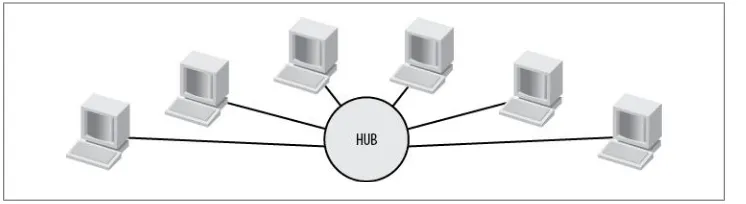
A hub is like a repeater, except that while a repeater may have only two connectors, a hub can have many more; that is, it repeats a signal over many cables as opposed to just one. Figure 2-2 shows a hub connecting several computers to a network.
In Ethernet network design, repeaters and hubs are treated the same way. The 5-4-3 rule of Ethernet design states that between any two nodes on an Ethernet network, there can be only five segments, connected via four repeaters, and only three of the segments can be populated. This rule, which seems odd in the context of today’s net-works, was the source of much pain for those who didn’t understand it.
Figure 2-1. Repeater extending a single 10Base-T link
As hubs became less expensive, extra hubs were often used as repeaters in more com-plex networks. Figure 2-3 shows an example of how two remote groups of users could be connected using hubs on each end and a repeater in the middle.
Hubs are very simple devices. Any signal received on any port is repeated out every other port. Hubs are purely physical and electrical devices, and do not have a presence on the network (except possibly for management purposes). They do not alter frames or make decisions based on them in any way.
Figure 2-4 illustrates how hubs operate. As you might imagine, this model can become problematic in larger networks. The traffic can become so intensive that the network becomes saturated—if someone prints a large file, everyone on the network will suffer while the file is transferred to the printer over the network.
If another device is already using the wire, the sending device will wait a bit and then try to transmit again. When two stations transmit at the same time, a collision occurs. Each station records the collision, backs off again, and then retransmits. On very busy networks, a lot of collisions will occur.
With a hub, more stations are capable of using the network at any given time. Should all of the stations be active, the network will appear to be slow because of the excessive collisions.
Figure 2-3. Repeater joining hubs
Figure 2-4. Hubs repeat inbound signals to all ports, regardless of type or destination
Collisions are limited to network segments. An Ethernet network segment is a section of network where devices can communicate using Layer-2 MAC addresses. To com-municate outside an Ethernet segment, an additional device, such as a router, is
required. Collisions are also limited to collision domains. A collision domain is an area of an Ethernet network where collisions can occur. If one station can prevent another from sending because it is using the network, these stations are in the same collision domain.
A broadcast domain is the area of an Ethernet network where a broadcast will be propa-gated. Broadcasts stay within a Layer-3 network (unless forwarded), which is usually bordered by a Layer-3 device such as a router. Broadcasts are sent through switches (Layer-2 devices) but stop at routers.
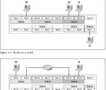
Many people mistakenly think that broadcasts are contained within switches or virtual LANs (VLANs). I think this is because they are so contained in a properly designed network. If you connect two switches with a crossover cable—one configured with VLAN 10 on all ports and the other configured with VLAN 20 on all ports—hosts plugged into each switch will be able to communicate if they are on the same IP net-work. Broadcasts and IP networks are not limited to VLANs, though it is very tempting to think so.
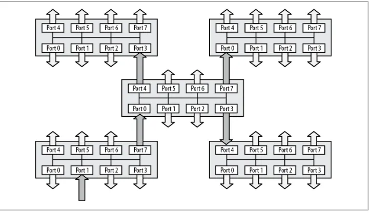
Figure 2-5 shows a network of hubs connected via a central hub. When a frame enters the hub on the bottom left on Port 1, the frame is repeated out every other port on that hub, which includes a connection to the central hub. The central hub in turn repeats the frame out every port, propagating it to the remaining hubs in the network. This design replicates the backbone idea, in that every device on the network will receive every frame sent on the network.
In large networks of this type, new problems can arise. Late collisions occur when two stations successfully test for a clear network and then transmit, only to encounter a collision. This condition can occur when the network is so large that the propagation of a transmitted frame from one end of the network to the other takes longer than the test used to detect whether the network is clear.
One of the other major problems when using hubs is the possibility of broadcast storms. Figure 2-6 shows two hubs connected with two connections. A frame enters the network on Hub 1 and is replicated on every port, which includes the two connec-tions to Hub 2, which now repeats the frame out all of its ports, including the two ports connecting the two switches. Once Hub 1 receives the frame, it again repeats it out every interface, effectively causing an endless loop.
Figure 2-6. Broadcast storm
Anyone who’s ever lived through a broadcast storm on a live network knows how much fun it can be—especially if you consider your boss screaming at you to be fun. It’s extra special fun when your boss’s boss joins in. Symptoms of a broadcast storm include every device essentially being unable to send any frames on the network due to constant network traffic, all status lights on the hubs staying on constantly instead of blinking normally, and (perhaps most importantly) senior executives threatening you with bod-ily harm.
The only way to resolve a broadcast storm is to break the loop. Shutting down and restarting the network devices will just start the cycle again. Because hubs are not gen-erally manageable, it can be quite a challenge to find a Layer-2 loop in a crisis.
Hubs have a lot of drawbacks, and modern networks rarely employ them. Hubs have long since been replaced by switches, which offer greater speed, automatic loop detec-tion, and a host of additional features.
Switches
The next step in the evolution of Ethernet was the switch. Switches differ from hubs in that switches play an active role in how frames are forwarded. Remember that a hub simply repeats every signal it receives via any of its ports out every other port. A switch, in contrast, keeps track of which devices are on which ports, and forwards frames only to the devices for which they are intended.
What we refer to as a packet in TCP/IP is called a frame when speaking about hubs, bridges, and switches. Technically, they are different things, since a TCP packet is encapsulated with Layer-2 information to form a frame. However, the terms “frames” and “packets” are often thrown around interchangeably (I’m guilty of this myself). To be perfectly cor-rect, always refer to frames when speaking of hubs and switches.
When other companies began developing switches, Cisco had all of its energies con-centrated in routers, so it did not have a solution that could compete. Hence, Cisco did the smartest thing it could do at the time—it acquired the best of the new switching companies, like Kalpana, and added their devices to the Cisco lineup. As a result, Cisco switches did not have the same operating system that their routers did. While Cisco routers used the Internetwork Operating System (IOS), the Cisco switches sometimes used menus, or an operating system called CatOS (Cisco calls its switch line Catalyst; thus, the Catalyst Operating System was CatOS).
A quick note about terminology: the words “switching” and “switch” have multiple meanings, even in the networking world. There are Ethernet switches, Frame Relay switches, Layer-3 switches, multilayer switches, and so on. Here are some terms that are in common use:
Switch
The general term used for anything that can switch, regardless of discipline or what is being switched. In the networking world, a switch is generally an Ethernet switch. In the telecom world, a switch can be many things, none of which we are discussing in this chapter.
Ethernet switch
Layer-3 switch
This is a switch with routing capabilities. Generally, VLANs can be configured as virtual interfaces on a Layer-3 switch. True Layer-3 switches are rare today; most switches are now multilayer switches.
Multilayer switch
Similar to a Layer-3 switch, but may also allow for control based on higher layers in packets. Multilayer switches allow for control based on TCP, UDP, and even details contained within the data payload of a packet.
Switching
In Ethernet, switching is the act of forwarding frames based on their destination MAC addresses. In telecom, switching is the act of making a connection between two parties. In routing, switching is the process of forwarding packets from one interface to another within a router.
Switches differ from hubs in one very fundamental way: a signal that comes into one port is not replicated out every other port on a switch as it is in a hub (unless, as we’ll see, the packet is destined for all ports). While modern switches offer a variety of more advanced features, this is the one that makes a switch a switch.
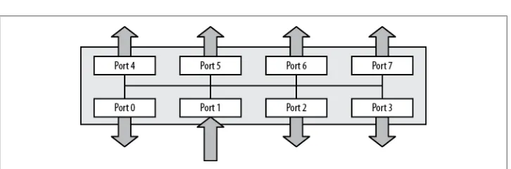
Figure 2-7 shows a switch with paths between Ports 4 and 6, and Ports 1 and 7. The beauty is that frames can be transmitted along these two paths simultaneously, which greatly increases the perceived speed of the network. A dedicated path is created from the source port to the destination port for the duration of each frame’s transmission. The other ports on the switch are not involved at all.
Figure 2-7. A switch forwards frames only to the ports that need to receive them
So, how does the switch determine where to send the frames being transmitted from different stations on the network? Every Ethernet frame contains the source and des-tination MAC address for the frame. The switch opens the frame (only as far as it needs to), determines the source MAC address, and adds that MAC address to a table if it is not already present. This table, called the content-addressable memory table (or CAM table) in CatOS, and the MAC address table in IOS, contains a map of which MAC addresses have been discovered on which ports. The switch then determines the frame’s
destination MAC address and checks the table for a match. If a match is found, a path is created from the source port to the appropriate destination port. If there is no match, the frame is sent to all ports.
When a station using IP needs to send a packet to another IP address on the same network, it must first determine the MAC address for the destination IP address. To accomplish this, IP sends out an Address Resolution Protocol (ARP) request packet. This packet is a broadcast, so it is sent out all switch ports. The ARP packet, when encapsulated into a frame, now contains the requesting station’s MAC address, so the switch knows which port to assign as the source. When the destination station replies that it owns the requested IP address, the switch knows which port the destination MAC address is located on (the reply frame will contain the replying station’s MAC address).
Running the show mac-address-table command on an IOS-based switch displays the table of MAC addresses and corresponding ports. Multiple MAC addresses on a single port usually indicates that the port in question is a connection to another switch or networking device:
Switch1-IOS>sho mac-address-table Legend: * - primary entry
age - seconds since last seen n/a - not available
vlan mac address type learn age ports
---+---+---+---+---+---* 24 0013.bace.e5f8 dynamic Yes 165 Gi3/4
* 24 0013.baed.4881 dynamic Yes 25 Gi3/4 * 24 0013.baee.8f29 dynamic Yes 75 Gi3/4 * 4 0013.baeb.ff3b dynamic Yes 0 Gi2/41 * 24 0013.baee.8e89 dynamic Yes 108 Gi3/4
* 18 0013.baeb.01e0 dynamic Yes 0 Gi4/29 * 24 0013.2019.3477 dynamic Yes 118 Gi3/4 * 18 0013.bab3.a49f dynamic Yes 18 Gi2/39 * 18 0013.baea.7ea0 dynamic Yes 0 Gi7/8 * 18 0013.bada.61ca dynamic Yes 0 Gi4/19 * 18 0013.bada.61a2 dynamic Yes 0 Gi4/19 * 4 0013.baeb.3993 dynamic Yes 0 Gi3/33
From the preceding output, you can see that if the device with the MAC address 0013.baeb.01e0 attempts to talk to the device with the MAC address 0013.baea.7ea0, the switch will set up a connection between ports Gi4/29 and Gi7/8.
You may notice that I specify the command show in my descriptions, and then use the shortened version sho while entering commands. Cisco
This information is also useful if you need to figure out where a device is connected to a switch. First, get the MAC address of the device you’re looking for. Here’s an example from Solaris:
[root@unix /]$ifconfig -a
lo0: flags=1000849<UP,LOOPBACK,RUNNING,MULTICAST,IPv4> mtu 8232 index 1 inet 127.0.0.1 netmask ff000000
dmfe0: flags=1000843<UP,BROADCAST,RUNNING,MULTICAST,IPv4> mtu 1500 index 2 inet 172.16.1.9 netmask ffff0000 broadcast 172.16.255.255
ether 0:13:ba:da:d1:ca
Then, take the MAC address (shown on the last line) and include it in the IOS com-mand show mac-address-table | include mac-address:
Switch1-IOS>sho mac-address-table | include 0013.bada.d1ca * 18 0013.bada.d1ca dynamic Yes 0 Gi3/22
Note the format when using MAC addresses, as different systems dis-play MAC addresses differently. You’ll need to convert the address to the appropriate format for IOS or CatOS. IOS displays each group of two-byte pairs separated by a period. Solaris and most other operating systems display each octet separated by a colon or hyphen (CatOS uses a hyphen as the delimiter when displaying MAC addresses in hexadec-imal). Some systems may also display MAC addresses in decimal, while others use hexadecimal.
The output from the preceding command shows that port Gi3/22 is where our server is connected.
In NX-OS, the command is the same as IOS, though the interface names reflect the Nexus hardware (in this case, a 5010 with a 2148T configured as FEX100):
NX-5K-1(config-if)# sho mac-address-table
VLAN MAC Address Type Age Port
---+---+---+---+---100 0005.9b74.b811 dynamic 0 Po---+---+---+---+---100
100 0013.bada.d1ca dynamic 40 Eth100/1/2 Total MAC Addresses: 2
On a switch running CatOS, this works a little differently because the show cam com-mand contains an option to show a specific MAC address:
Switch1-CatOS: (enable)sho cam 00-00-13-ba-da-d1-ca
* = Static Entry. + = Permanent Entry. # = System Entry. R = Router Entry. X = Port Security Entry $ = Dot1x Security Entry
VLAN Dest MAC/Route Des [CoS] Destination Ports or VCs / [Protocol Type] ---- --- --- ---20 00-13-ba-da-d1-ca 3/48 [ALL]
Total Matching CAM Entries Displayed =1
Switch Types
Cisco switches can be divided into two types: fixed-configuration and modular switches. Fixed-configuration switches are smaller—usually one rack unit (RU) in size. These switches typically contain nothing but Ethernet ports and are designed for sit-uations where larger switches are unnecessary.
Examples of fixed-configuration switches include the Cisco 2950, 3550, and 3750 switches. The 3750 is capable of being stacked. Stacking is a way of connecting multiple switches together to form a single logical switch. This can be useful when you need more than the maximum number of ports available on a single fixed-configuration switch (48). The limitation of stacking is that the backplane of the stack is limited to 32 or 64 gigabits per second (Gbps). For comparison, some of the chassis-based mod-ular switches can support 720 Gbps on their backplanes. These large modmod-ular switches are usually more expensive than a stack of fixed-configuration switches, however. The benefits of fixed-configuration switches include:
Price
Fixed-configuration switches are generally much less expensive than their modular cousins.
Size
Fixed-configuration switches are usually only 1 RU in size. They can be used in closets and in small spaces where chassis-based switches do not fit. Two switches stacked together are still smaller than the smallest chassis switch.
Weight
Fixed-configuration switches are lighter than even the smallest chassis switches. Two people, at minimum, are required to install most chassis-based switches. Power
Fixed-configuration switches are all capable of operating on normal household power, and hence can be used almost anywhere. The larger chassis-based switches require special power supplies and AC power receptacles when fully loaded with modules. Many switches are also available with DC power options.
On the other hand, Cisco’s larger, modular chassis-based switches have the following advantages over their smaller counterparts:
Expandability
Flexibility
The Cisco 6500 chassis will accept modules that provide services outside the range of a normal switch. Such modules include:
• Firewall Services Modules (FWSMs)
• Intrusion Detection System Modules (IDSMs) • Application Control Engines (ACE) modules • Network Analysis Modules (NAMs)
• WAN modules (FlexWAN) Redundancy
Some fixed-configuration switches support a power distribution unit, which can provide some power redundancy at additional cost. However, Cisco’s chassis-based switches all support multiple power supplies (older 4000 chassis switches actually required three power supplies for redundancy and even more to support VoIP). Most chassis-based switches support dual supervisors as well.
Speed
The Cisco 6500 chassis employing Supervisor-720 (Sup-720) processors supports up to 720 Gbps of throughput on the backplane. The fastest backplane in a fixed-configuration switch—the Cisco 4948—supports only 48 Gbps. The 4948 switch is designed to be placed at the top of a rack in order to support the devices in the rack. Due to the specialized nature of this switch, it cannot be stacked and is there-fore limited to 48 ports.
Chassis-based switches do have some disadvantages. They can be very heavy, take up a lot of room, and require a lot of power. If you need the power and flexibility offered by a chassis-based switch, however, the disadvantages are usually just considered part of the cost of doing business.
Cisco’s two primary chassis-based Catalyst switches are the 4500 series and the 6500 series. There is an 8500 series as well, but these switches are rarely seen in corporate environments.
The Nexus switches can fit in either camp depending on the model. The Nexus 7000 chassis switch is available in a 10-slot or 18-slot chassis. These models have all the benefits and drawbacks of any other chassis switch, though as of this writing the 7000 does not support many service modules. Word on the street is that this will change as the product line evolves.
The Nexus 5000, having only one (5010) or two (5020) expansion modules can be expanded through the use of fabric extenders (FEXs). FEXs appear to be physical switches, but are actually more like a module connected to the 5000s. The Nexus 2000 switches act as FEXs. With the capability to connect up to twelve 48-port FEXs to a single (or pair of) Nexus 5000s, each Nexus 5000 behaves more like a 12-slot chassis than a fixed-configuration switch. The Nexus hardware chapter will go into more detail regarding Nexus expandability.
Planning a Chassis-Based Switch Installation
Installing chassis-based switches requires more planning than installing smaller switches. There are many elements to consider when configuring a chassis switch. You must choose the modules (sometimes called blades) you will use and then determine what size power supplies you need. You must decide whether your chassis will use AC or DC power and what amperage the power supplies will require. Chassis-based switches are large and heavy, so you must ensure that there is adequate rack space. Here are some of the things you need to think about when planning a chassis-based switch installation.
Rack space
Chassis switches can be quite large. The 6513 switch occupies 19 RU of space. The NEBS version of the 6509 takes up 21 RU. The 10-slot Nexus 7010 consumes 21 RU as well, while the 18-slot model 7018 requires 25 RU. A seven-foot telecom rack is 40 RU, so these larger switches use up a significant portion of the available space.
Be careful when planning rack space for Nexus switches. The Nexus 5000 series is as deep as a rack-mount server and requires the full depth of a cabinet for mounting. The Nexus 5000 switches cannot be mounted in a standard two-post telecom rack.
The larger chassis switches are very heavy and should be installed near the bottom of the rack whenever possible. Smaller chassis switches (such as the 4506, which takes up only 10 RU) can be mounted higher in the rack.
Always use a minimum of two people when lifting heavy switches. Of-ten, a third person can guide the chassis into the rack. The chassis should be moved only after all the modules and power supplies have been removed.
Power
Depending on where you install your switch, you may need power supplies capable of using either AC or DC power. In the case of DC power supplies, make sure you specify A and B feeds. For example, if you need 40 amps of DC power, you’d request 40 amps DC—A and B feeds. This means that you’ll get two 40-amp power circuits for failover purposes. Check the Cisco documentation regarding grounding information. Most collocation facilities supply positive ground DC power.
For AC power supplies, you’ll need to specify the voltage, amperage, and socket needed for each feed. Each power supply typically requires a single feed, but some will take two or more. You’ll need to know the electrical terminology regarding plugs and re-ceptacles. All of this information will be included in the documentation for the power supply, which is available on Cisco’s website. For example, the power cord for a power supply may come with a NEMA L6-20P plug, which will require NEMA L6-20R re-ceptacles. The P and R on the ends of the part numbers describe whether the part is a plug or a receptacle (the NEMA L6-20 is a twist-lock 250-volt AC 16-amp connector). The power cables will connect to the power supplies via a large rectangular connector. This plug will connect to a receptacle on the power supply, which will be surrounded by a clamp. Always tighten this clamp to avoid the cable popping out of the receptacle when stressed.
Cooling
Many chassis switches are cooled from side to side: the air is drawn in on one side, pulled across the modules, and blown out the other side. Usually, rackmounting the switches allows for plenty of airflow. Be careful if you will be placing these switches in cabinets, though. Cables are often run on the sides of the switches, and if there are a lot of them, they can impede the airflow.
The NEBS-compliant 6509 switch moves air vertically and the modules sit vertically in the chassis. With this switch, you can see the air vents plainly on the front of the chassis. Take care to keep them clear. All Nexus switches are designed for front-to-back airflow to facilitate hot-/cold-aisle data-center designs. Be careful when mounting these switches. Some people like to have the Ethernet ports in the front of the rack. With Nexus, this position is a bad idea, as air will flow in the wrong direction in the rack.
I once worked on a project where we needed to stage six 6506 switches. We pulled them out of their crates and put them side by side on a series of pallets. We didn’t stop to think that the heated exhaust of each switch was blowing directly into the input of the next switch. By the time the air got from the intake of the first switch to the exhaust of the last switch, it was so hot that the last switch shut itself down. Always make sure you leave ample space between chassis switches when installing them.
Installing and removing modules
Modules for chassis-based switches are inserted into small channels on both sides of the slot. Be very careful when inserting modules, as it is very easy to miss the channels and get the modules stuck. Many modules—especially service modules like FWSMs, IDSMs, CSMs and ACE—are densely packed with components. I’ve seen $40,000 modules ruined by engineers who forced them into slots without properly aligning them. Remember to use a static strap, too.
Anytime you’re working with a chassis or modules, you should use a static strap. They’re easy to use, and come with just about every piece of hardware these days. I know you feel like a dork using them, but imagine how you’ll feel when you trash a $400,000 switch.
Routing cables
CHAPTER 3
Autonegotiation
When I get called to a client’s site to diagnose a network slowdown or a “slow” device, the first things I look at are the error statistics and the autonegotiation settings on the switches as well as the devices connected to them. If I had to list the most common problems I’ve seen during my years in the field, autonegotiation issues would be in the top five, if not number one.
Why is autonegotiation such a widespread problem? The truth is, too many people don’t really understand what it does and how it works, so they make assumptions that lead to trouble.
What Is Autonegotiation?
Autonegotiation is the feature that allows a port on a switch, router, server, or other device to communicate with the device on the other end of the link to determine the optimal duplex mode and speed for the connection. The driver then dynamically con-figures the interface to the values determined for the link. Let’s examine the configu-ration parameters:
Speed
Speed is the rate of the interface, usually listed in megabits per second (Mbps). Common Ethernet speeds include 10 Mbps, 100 Mbps, and 1,000 Mbps. 1,000 Mbps Ethernet is also referred to as Gigabit Ethernet. Many switches now support 10 Gbps Ethernet, and 100 Gbps is on the horizon as well.
Duplex
Duplex refers to how data flows on the interface. On a half duplex interface, data can only be transmitted or received at any given time. A conversation on a two-way radio is usually half-duplex—each person must push a button to talk and, while talking, that person cannot listen. A full-duplex interface, on the other hand, can send and receive data simultaneously. A conversation on a telephone is full duplex.
How Autonegotiation Works
First, let’s cover what autonegotiation does not do: when autonegotiation is enabled on a port, it does not automatically determine the configuration of the port on the other side of the Ethernet cable and then match it. This is a common misconception that often leads to problems.
Autonegotiation is a protocol and, as with any protocol, it only works if it’s running on both sides of the link. In other words, if one side of a link is running autonegotiation and the other side of the link is not, autonegotiation cannot determine the speed and duplex configuration of the other side. If autonegotiation is running on the other side of the link, the two devices decide together on the best speed and duplex mode. Each interface advertises the speeds and duplex modes at which it can operate, and the best match is selected (higher speeds and full duplex are preferred).
The confusion exists primarily because autonegotiation always seems to work. This is because of a feature called parallel detection, which kicks in when the autonegotiation process fails to find autonegotiation running on the other end of the link. Parallel de-tection works by sending the signal being received to the local 10Base-T, 100Base-TX, and 100Base-T4 drivers. If any one of these drivers detects the signal, the interface is set to that speed.
Parallel detection determines only the link speed, not the supported duplex modes. This is an important consideration because the common modes of Ethernet have dif-fering levels of duplex support:
10Base-T
10Base-T was originally designed without full-duplex support. Some implemen-tations of 10Base-T support full duplex, but many do not.
100Base-T
100Base-T has long supported full duplex, which has been the preferred method for connecting 100 Mbps links for as long as the technology has existed. However, the default behavior of 100Base-T is usually half duplex, and full-duplex support must be set manually.
1000Base-T
Gigabit Ethernet has a much more robust autonegotiation protocol than 10M or 100M Ethernet. Gigabit interfaces should be left to autonegotiate in most situations.
10 Gigabit
Because of the lack of widespread full-duplex support on 10Base-T and the typical default behavior of 100Base-T, when autonegotiation falls through to the parallel de-tection phase (which only detects speed), the safest thing for the driver to do is to choose half-duplex mode for the link.
As networks and networking hardware evolve, higher-speed links with more robust negotiation protocols will likely make negotiation problems a thing of the past. That being said, I still see 20-year-old routers in service, so knowing how autonegotiation works will be a valuable skill for years to come.
When Autonegotiation Fails
When autonegotiation fails on 10/100 links, the most likely cause is that one side of the link has been set to 100/full and the other side has been set to autonegotiation. This results in one side being 100/full and the other side being 100/half.
Figure 3-1 shows a half-duplex link. In a half-duplex environment, the receiving (RX) line is monitored. If a frame is present on the RX link, no frames are sent until the RX line is clear. If a frame is received on the RX line while a frame is being sent on the transmitting (TX) line, a collision occurs. Collisions cause the collision error counter to be incremented—and the sending frame to be retransmitted—after a random back-off delay. This may seem counterintuitive in a modern switched environment, but re-member that Ethernet was originally designed to work over a single wire. Switches and twisted pair came along later.
Figure 3-1. Half duplex
Figure 3-2 shows a full-duplex link. In full-duplex operation, the RX line is not moni-tored, and the TX line is always considered available. Collisions do not occur in full-duplex mode because the RX and TX lines are completely independent.
When one side of the link is full duplex and the other side is half duplex, a large number of collisions will occur on the half-duplex side. Because the full-duplex side sends frames without checking the RX line, if it’s a busy device, chances are it will be sending
frames constantly. The other end of the link, being half duplex, will listen to the RX line and will not transmit unless the RX line is available. It will have a hard time getting a chance to transmit and will record a high number of collisions, making the device appear to be slow on the network. The issue may not be obvious, because a half-duplex interface normally shows collisions, while a full-duplex interface does not. Since full duplex means never having to test for a clear-to-send condition, a full-duplex interface will not record any errors in this situation. The problem should present itself as exces-sive collisions, but only on the half-duplex side.
Figure 3-3 shows a link where autonegotiation has failed.
Figure 3-3. Common autonegotiation failure scenario
In the real world, if you see that an interface that is set to autonegotiation has negotiated to 100/half, chances are the other side is set to 100/full. 100 Mbps interfaces that do not support full duplex are rare, so properly configured autonegotiation ports should almost never end up config-ured for half duplex.