BACHELOR THESIS & COLLOQUIUM - ME 141502
CONCEPT FOR A LNG GAS HANDLING SYSTEM FOR A DUAL FUEL ENGINE
LEONARDO RISMAN MARULI SITINJAK NRP. 4213101029
SUPERVISORS:
Prof. Dr.-Ing. Michael Rachow M.Sc. Steffen Loest
DOUBLE DEGREE PROGRAM
MARINE ENGINEERING DEPARTMENT FACULTY OF MARINE TECHNOLOGY
BACHELOR THESIS & COLLOQUIUM - ME 141502
CONCEPT FOR A LNG GAS HANDLING SYSTEM FOR A DUAL FUEL ENGINE
LEONARDO RISMAN MARULI SITINJAK NRP. 4213101029
SUPERVISORS:
Prof. Dr.-Ing. Michael Rachow M.Sc. Steffen Loest
DOUBLE DEGREE PROGRAM
MARINE ENGINEERING DEPARTMENT FACULTY OF MARINE TECHNOLOGY
SKRIPSI - ME 141502
KONSEP SISTEM PENANGANAN GAS LNG PADA MESIN
DUAL FUEL
LEONARDO RISMAN MARULI SITINJAK NRP. 4213101029
DOSEN PEMBIMBING:
Prof. Dr.-Ing. Michael Rachow M.Sc. Steffen Loest
PROGRAM DOUBLE DEGREE
DEPARTEMEN TEKNIK SISTEM PERKAPALAN FAKULTAS TEKNOLOGI KELAUTAN
i
APPROVAL FORM
CONCEPT FOR A LNG GAS HANDLING SYSTEM FOR A DUAL FUEL ENGINE
BACHELOR THESIS
Submitted to Comply One of The Requirements to Obtain a Bachelor Engineering Degree
in
Double Degree of Marine Engineering (DDME) Program Department of Marine Engineering - Faculty of Marine Technology
Institut Teknologi Sepuluh Nopember (ITS) Department of Maritime Studies - Faculty of Engineering
Hochschule Wismar, University of Applied Sciences Technology, Business and Design
Submitted by:
LEONARDO RISMAN MARULI SITINJAK
NRP. 4213101029
Approved by Bachelor Thesis Supervisor:
Prof. Dr.-Ing. Michael Rachow ( )
M.Sc. Steffen Loest ( )
ii
iii
APPROVAL FORM
CONCEPT FOR A LNG GAS HANDLING SYSTEM FOR A DUAL FUEL ENGINE
BACHELOR THESIS
Submitted to Comply One of The Requirements to Obtain a Bachelor Engineering Degree
in
Double Degree of Marine Engineering (DDME) Program Department of Marine Engineering - Faculty of Marine Technology
Institut Teknologi Sepuluh Nopember (ITS) Department of Maritime Studies - Faculty of Engineering
Hochschule Wismar, University of Applied Sciences Technology, Business and Design
Submitted by:
LEONARDO RISMAN MARULI SITINJAK
NRP. 4213101029
Approved by
Head of Marine Engineering Department
Dr. Eng. M. Badrus Zaman, S.T., M.T. NIP. 1977 0802 2008 01 1007
iv
v
APPROVAL FORM
CONCEPT FOR A LNG GAS HANDLING SYSTEM FOR A DUAL FUEL ENGINE
BACHELOR THESIS
Submitted to Comply One of The Requirements to Obtain a Bachelor Engineering Degree
in
Double Degree of Marine Engineering (DDME) Program Department of Marine Engineering - Faculty of Marine Technology
Institut Teknologi Sepuluh Nopember (ITS) Department of Maritime Studies - Faculty of Engineering
Hochschule Wismar, University of Applied Sciences Technology, Business and Design
Submitted by:
LEONARDO RISMAN MARULI SITINJAK
NRP. 4213101029
Approved by
Representative of Hochschule Wismar in Indonesia
Dr.-Ing. Wolfgang Busse
vi
vii
DECLARATION OF HONOR
I, who signed below hereby confirm that:
This final project report has written without any plagiarism act, and confirm consciously that all the data, concepts, design, references, and material in this report own by Marine Power Plant Laboratory (MPP) in department of Marine Engineering ITS which are the product of research study and reserve the right to use for further research study and its development.
Name : Leonardo Risman Maruli Sitinjak
NRP : 4213 101 029
Bachelor Thesis Title : Concept For a LNG Gas Handling System For a Dual Fuel Engine
Department : Double Degree Program of Marine Engineering
If there is plagiarism act in the future, I will fully responsible and receive the penalty given by ITS and Hochschule Wismar according to the regulation applied.
Surabaya, July 2017
viii
ix
CONCEPT FOR A LNG GAS HANDLING SYSTEM FOR A DUAL FUEL ENGINE
Name : Leonardo Risman Maruli Sitinjak NRP : 4213 101 029
Department : Double Degree Program of Marine Engineering Supervisor : Prof. Dr.-Ing. Michael Rachow
M.Sc. Steffen Loest
ABSTRACT
x
KONSEP UNTUK SISTEM PENANGANAN GAS LNG PADA MESIN BERBAHAN BAKAR GANDA
Nama : Leonardo Risman Maruli Sitinjak NRP : 4213 101 029
Departemen : Double Degree Program of Marine Engineering Dosen Pembimbing : Prof. Dr.-Ing. Michael Rachow
M.Sc. Steffen Loest
ABSTRAK
xi
PREFACE
This bachelor submitted to fulfil the requirement to obtain Bachelor of Engineering Degree in Department of Marine Engineering, Sepuluh Nopember Institute of Technology and Hochschule Wismar.
First of all, I would like to thank God for blessing and helping me to complete this bachelor thesis timely. I wish to express my gratitude to my supervisor Prof. Dr.-Ing. Michael Rachow and M.Sc. Steffen Loest for guidance, support, knowledge and advice given for accomplishing this thesis. My thanks to Dipl. Ing. Hartmut Schmidt for the guidance to obtain some data required of engine operation in laboratory. My thanks to Mrs. Rau, Jost, and Ben who helped me during my stay and study in Rostock, Germany.
The greatest honor and appreciation would be finally dedicated to my beloved parents and all my family for the support, love, care and motivation. I would also addressed my appreciation to my beloved family of Marine Engineering students, especially for Double Degree class of 2013, thank you so much for being such a great companion during our togetherness at campus.
Surabaya, July 2017
xii
xiii
LIST OF CONTENTS
APPROVAL FORM ... III DECLARATION OF HONOR ... VII ABSTRACT ... IX ABSTRAK ... X PREFACE ... XI LIST OF CONTENTS ... XI LIST OF FIGURES ... XVII LIST OF TABLES ... XIX
LIST OF ABBREVIATIONS ... XXI
CHAPTER I INTRODUCTION ... 1
1.1 Background ... 1
1.2 Statement of Problems ... 3
1.3 Research Limitations... 4
1.4 Research Objectives ... 4
1.5 Research Benefits... 4
CHAPTER II RESEARCH METHODOLOGY... 5
2.1 Schematic Diagram of Work ... 5
2.2 Detail of Work ... 6
2.2.1 Problem of Statement ... 6
2.2.2 Literature Study ... 6
2.2.2 Collecting Data ... 6
2.2.3 Fuel Oil Consumption Calculation ... 7
2.2.4 Fuel Gas Consumption Calculation ... 7
2.2.5 Determine the Required Components of Fuel Gas Supply System ... 7
2.2.6 Design the Concept of Fuel Gas Supply System ... 8
2.2.7 Installation Suggest for the Plant ... 8
xiv
CHAPTER III FUEL GAS CONSUMPTION CALCULATION AND ANALYSIS ... 9
3.1 Engine Overview ... 9
3.2 Fuel Oil Consumption Analysis ... 10
3.3 LNG Consumption Analysis ... 13
3.3.1 Power Reduction of Engine MAN 6L23/30 A ... 13
3.3.2 Specific Fuel Gas Consumption Analysis ... 16
CHAPTER IV COMPONENT SELECTION OF FUEL GAS SUPPLY SYSTEM ... 19
4.1 LNG Storage Tank ... 19
4.1.1 Double Walled Fuel Storage Tank ... 21
4.1.2 Single Walled Fuel Storage Tank ... 22
4.1.3 ISO (International Organization for Standardization) Marine Type LNG Container ... 22
4.1.4 LNG Tank Selection ... 23
4.2 Water Spray Pump ... 24
4.3 Vaporizer ... 26
4.4 LNG Pump ... 30
4.5 Gas Valve Unit ... 30
4.6 Pipe Diameter Calculation ... 33
CHAPTER V DESIGN ARRANGEMENT ... 35
5.1 Fuel Gas Supply System ... 35
5.2 Design Requirement ... 36
5.2.1 LNG Storage Tank ... 36
5.2.2 Gas Piping System ... 37
5.2.3 System Configuration ... 37
5.2.4 Gas Supply System in gas machinery spaces ... 38
5.2.5 Ventilation system ... 38
5.2.6 Safety Functions of Gas supply system ... 39
5.3 Design Arrangement of Fuel Gas Supply System ... 40
5.3.1 LNG Tank ... 40
xv
5.3.3 Ventilation in double piping system ... 42
5.3.4 Gas Valve Unit ... 43
5.3.5 Inert gas system ... 44
CHAPTER VI CONCLUSIONS ... 45
5.1 Conclusions ... 45
REFERENCES ... 49
ATTACHMENT 1 CONCEPT DESIGN OF FUEL GAS SUPPLY SYSTEM ... 51
ATTACHMENT 2 LNG TANK DESIGN AND SAFETY ASPECT ... 52
ATTACHMENT 3 SIDE VIEW DESIGN OF COMPONENT INSTALLATION ... 53
ATTACHMENT 4 TOP VIEW DESIGN OF COMPONENT INSTALLATION ... 54
ATTACHMENT 5 LNG TANK TYPE 2200 H TECHNICAL DATA ... 55
ATTACHMENT 6 LNG PUMP VANZETTI TECHNICAL DATA ... 57
ATTACHMENT 7 CIRCULATING WATER VAPORIZER TECHNICAL DATA .... 59
ATTACHMENT 8 GAS VALVE UNIT TECHNICAL DATA ... 61
ATTACHMENT 9 WATER SPRAY PUMP TECHNICAL DATA ... 62
xvi
xvii
LIST OF FIGURES
xviii
xix
LIST OF TABLES
xx
xxi
LIST OF ABBREVIATIONS
Abbreviations Description
LNG Liquefied Natural Gas
PM Particulate Matter
HFO Heavy Fuel Oil
MDO Marine Diesel Oil
LSHFO Low Sulphur Heavy Fuel Oil SFOC Specific Fuel Oil Consumption SFGC Specific Fuel Gas Consumption
FOC Fuel Oil Consumption
BHP Engine Power
t Operating Time
LHV Lower Heating Value
ρ Density
IMO International Maritime Organization
IGC International Gas Carrier
ISO International Organization for Standardization
C Capacity
A Surface Area
v Velocity
d Diameter
Q Heat Energy
m Mass of the Substance
C_p Specific Heat
T Temperature
GVU Gas Valve Unit
MAWP Maximum Allowable Working Pressure
xxii
1
CHAPTER I
INTRODUCTION
1.1 Background
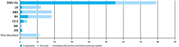
Liquefied Natural Gas (LNG) has been used as marine fuel for more than 50 years since the world’s first commercial seaborne trade of LNG began in 1964, shipping LNG from Algeria to the U.K [1]. The liquefied natural gas as a marine fuel is regarded as a proven solution for marine applications. The number of ships using LNG as fuel is increasing fast and more and more infrastructure projects are planned or proposed along the main shipping lanes. 63 LNG-fuelled ships (excluding LNG carriers) already operate worldwide, while another 76 new buildings are confirmed (as of May 2015) [2]. Figure 1.1 below shows the number of LNG powered ships in operation and on order by class society.
Figure 1.1 Number of LNG Powered Ships in operation and on order Source: LNG as Ship Fuel (Wuersig 2015)
The main emission product from a diesel engine are CO2, NOx, SOx and particulate matter (PM). These emissions can increasing the temperature on earth, affect the air quality, global warming and other health problems that can impact the environmental. The use of LNG as marine fuel is the proven solution and will contribute to a reduction of these emissions. These reductions will have significant environmental benefits such as improved local air quality, reduced acid rain and contribute to limit global warming.
According to DNV GL, when LNG is used as a ship fuel and in the replacement of conventional oil-based fuels (heavy fuel oil, marine gas oil, or distillate fuels) is the significant reduction in local air pollution - ranging from emissions of SOx and NOx to carbon dioxide, particulates (PM) and black carbon. The complete removal
2
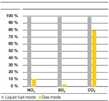
20%. As a fuelling option, LNG offers multiple advantages to both human health and the environment. Figure 1.2 below shows the gas emissions reduction by using LNG as a ship fuel.
Figure 1.2 Gas Emissions Reduction by Using LNG as a Ship Fuel Source: MAN Diesel & Turbo “Dual Fuel Upgrade”
One of the main reason that makes LNG become the preferable fuel is the lower price compared to Heavy Fuel Oil (HFO), Marine Diesel Oil (MDO) and Low Sulphur Heavy Fuel Oil (LSHFO). DNV GL was made fuel price scenario for the basic assumption. Starting year for the fuel price scenario is 2010 and 650 $/t (=15.3 $/mmBTU) for HFO and 900 $/t (=21.2 $/mmBTU) for MGO are set. LNG is set at 13 $/mmBTU which includes small-scale distribution costs of 4 $/mmBTU [4]. Figure 1.3 below shows the fuel price scenario of HFO, MDO, LSHFO, and LNG.
Figure 1.3 Fuel Price Scenario
3 According to the facts above, it is possible to use LNG as marine fuel. At the laboratory of maritime studies department in Warnemünde, a diesel engine type MAN 6L23/30A is installed. For future research activities, it is intended to change the engine operation mode from diesel to dual fuel. It’s required an additional components to supply LNG from storage tank to engine manifold, such as LNG tank, water spray pump, LNG pump, vaporizer, and gas valve unit (GVU). In this bachelor thesis, will discuss about the concept design of fuel gas supply system from storage tank until the engine manifold based on legal rules and safety aspects that required by regulation.
1.2 Statement of Problems
Based on the description above, the problem statement that can be concluded in this thesis are:
1. How to determine the fuel oil and fuel gas consumption at different loads? There are several input parameters used on the calculation of fuel oil and fuel gas consumption, such as: specific fuel oil consumption (SFOC), specific fuel gas consumption (SFGC), and operating time. For fuel oil consumption calculation, the SFOC will be obtained from data actual of engine operation. For fuel gas consumption calculation, the SFGC will be obtained from engine project guide that has been converted to dual fuel engine. The operating time of engine operation is 8 hours where this number is required to calculate the capacity of LNG tank.
2. How to determine the required components of gas supply system from storage tank until engine manifold? To determine the required components is based on the project guide of dual fuel engine. In this bachelor thesis, there are three project guide that used as reference to determine the required components, such as MAN 51/60 DF, MAN 35/44 DF, and Wartsila 34 DF. The specification of the components is based on the fuel gas consumption calculation result.
3. How to design the gas supply from storage tank until engine manifold? Germanischer Lloyd and project guide of dual fuel engine are used as guidance to design the fuel gas supply system. In this bachelor thesis, the safety aspects also will be arranged for supporting the process of fuel gas supply, such as safety aspect in LNG tank, pipeline, gas valve unit, and engine room.
4
society. The dimension of the component should be considered because the laboratory of maritime studies department in Warnemünde have limited dimension.
1.3 Research Limitations
The limitation of the problem that discussed on this thesis are:
1. Calculation of fuel oil and fuel gas consumption based on the engine project guide and data actual of engine operation
2. Analysis of this research focus on the diesel engine type MAN 6L23/30A that installed in the engine laboratory at the department of maritime studies in Warnemünde
3. This thesis is focusing on the concept design of fuel gas supply system from storage tank until engine manifold
4. Economic analysis is not including in this thesis
1.4 Research Objectives
The objectives of this thesis are:
1. Determine the possible gas consumption at different loads 2. Determine the necessary components of the gas supply system
3. To design the P&I concept including special requirements for LNG and safety aspects
4. To arrange the LNG plant in the laboratory building with consideration of legal rules
1.5 Research Benefits
The benefits that can be obtained from this bachelor thesis are:
1. Understand the required equipment for fuel gas supply system that based on the calculation result
5
CHAPTER II
RESEARCH METHODOLOGY
2.1 Schematic Diagram of Work
No
Yes
Problem of StatementLiterature Study
Collecting Data
Calculate the fuel oil and fuel gas consumption at variation loads Determine the required components of
fuel gas supply system
Design the fuel gas supply system from storage tank until engine manifold Installation arrangement for the LNG
plant in the laboratory
Is it fitted to the
Engine Specification SFOC Data of Engine Operation
6
Figure 2.1 Methodology Flow Chart Diagram
2.2 Detail of Work
2.2.1 Problem of Statement
In this thesis, the main problem is changing the engine operation mode from diesel to dual fuel which installed inside the engine laboratory, at the department of maritime studies in Warnemünde. The diesel engine type is MAN 6L23/30A. According to the problem above, it generated problem formulation, such as gas consumption at variation loads, components of the gas supply system, design P & I concept including special requirements and safety aspects.
2.2.2 Literature Study
Literature study is the stage to get all the information to solve the problem obtained. Many information should be obtained, such as basic theory of LNG characteristics, how to calculate the fuel oil and fuel gas consumption, what are the supporting components of fuel gas supply system, what is the consideration to design the concept of fuel gas supply system, how to install the required component into the laboratory building and many others. Most of the information regarding concept design of fuel gas supply system can be obtained from Germanischer Lloyd as classification society and dual fuel engine project guide. Some information are also can be obtained from papers, journals, thesis and researches that able to support this thesis.
2.2.2 Collecting Data
In this stage, data collection is required to develop the concept of fuel gas supply system. The data supported in this thesis are engine specifications, dual fuel engine project guide, and classification regulation of gas supply systems. Engine
Conclusion
7 project guide is required to find out the engine specifications and engine dimensions. In this thesis, the calculation of fuel oil consumption and vaporizer is based on data actual of engine operation. Therefore, the engine will be operated to get the actual data of specific fuel oil consumption (SFOC), engine water cooling temperature and exhaust gas temperature.
2.2.3 Fuel Oil Consumption Calculation
In this stage, fuel oil consumption will be calculated in several variations of load, such as 10%, 25%, 50%, 75%, and 100%. The fuel oil consumption will be calculated based on the data from project guide and data actual of engine operation. Therefore, SFOC from project guide 6L23/30 A MAN is required to calculate the fuel consumption. The data actual of SFOC will be obtained after the engine operated.
2.2.4 Fuel Gas Consumption Calculation
In this stage, fuel gas consumption will be calculated to find out the storage tank capacity to store the fuel for certain time of operation, fuel pump capacity, vaporising system and gas valve unit specification. The value of specific fuel gas consumption (SFGC) is required to calculate the fuel gas consumption. There is no information about SFGC for engine
MAN 6L23/30 A. Therefore, the dual fuel engine project guide is needed as reference to get the value of SFGC, such as MAN 51/60 DF, MAN 35/44 DF and Wartsila 34 DF. These engine was converted from single fuel to dual fuel engine. The value of SFGC from each dual fuel engine project guide will be compared and choose the correct one as reference to calculate the fuel gas consumption of engine MAN 6L23/30 A.
2.2.5 Determine the Required Components of Fuel Gas Supply System
8
2.2.6 Design the Concept of Fuel Gas Supply System
After every consideration is met the requirement, then the next step is design the fuel gas supply system. In this stage, to design a P&I concept including special requirements for LNG and safety aspects from store tank until engine manifold. Safety aspects will be arranged according to Germanischer Lloyd regulation, component manufacturer requirement, and dual fuel engine project guide.
2.2.7 Installation Suggest for the Plant
After the concept design of fuel gas supply system met to the regulation and project guide of dual fuel engine, then all the components can be installed to the laboratory. In this stage, the placement location of each component will be considered because the laboratory at the department of maritime studies in Warnemünde has limited space. The consideration of installation suggest for the components of fuel gas supply system in the laboratory building should be based on the classification societies.
2.2.8 Conclusion
9
CHAPTER III
FUEL GAS CONSUMPTION CALCULATION AND ANALYSIS
In this chapter, the process of fuel oil consumption and fuel gas consumption calculation will be explained. All the parameters of calculation formula are from data actual of engine operation and data from engine project guide. Engine specifications and engine dimensions are required to calculate the fuel gas consumption.
3.1 Engine Overview
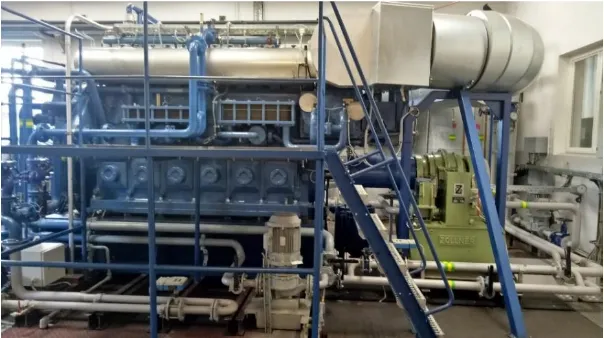
This research use engine type MAN 6l23/30 A as case study. The engine is installed inside the engine laboratory, at the department of maritime studies in Warnemünde. This engine had a power of 960 kW and use marine diesel oil (MDO) as the main fuel. This engine is equipped with water brake system. A water brake system is a type of fluid coupling used to absorb mechanical energy and usually consists of a turbine or propeller mounted in an enclosure filled with water. The water brake is utilized to measure the power output of the engine. The basic operation of a water brake uses the principle of viscous coupling. The output shaft of the engine is coupled to a fan that spins inside a concentric housing. While the engine is running, the housing is filled with a controlled amount of water. The more water that is allowed into the housing, the more load the engine will feel. According to the figure 3.1 below, the water brake in the engine laboratory, at the department of maritime studies in Warnemünde is indicated with a green colour.
10
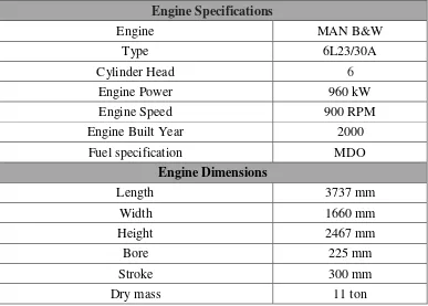
10 The manufacturer of the water brake is Zöllner type 9N38/12F. It has maximum power of 1200 kW and maximum speed of 3500 r/min. The required of water capacity of this water brake is 25.2 m3/h. The water temperature of water brake system should be maintained around 40 ℃. The detail specification of engine MAN 6L23/30 A can be seen in the table 3.1 below.
Table 3.1 Engine Specifications and Engine Dimensions
Engine Specifications
Engine
MAN B&W
Type
6L23/30A
Cylinder Head
6
Engine Power
960 kW
Engine Speed
900 RPM
Engine Built Year
2000
Fuel specification
MDO
Engine Dimensions
Length
3737 mm
Width
1660 mm
Height
2467 mm
Bore
225 mm
Stroke
300 mm
Dry mass
11 ton
3.2 Fuel Oil Consumption Analysis
Fuel oil consumption calculation is required to find out the fuel gas tank volume. There are 4 parameters to calculate the fuel oil consumption, as it can be seen in formula 3.1 below. Main engine is not working in 24 hours per day. It is only working in 8 hours per day and the volume of fuel gas tank will be calculated for demand 5 days. Before calculate the fuel gas consumption, it’s necessary to calculate the fuel oil consumption. In this study, fuel oil consumption will be calculated at variation loads by using formula 3.1 below
𝐅𝐎𝐂𝐥𝐨𝐚𝐝= 𝐁𝐇𝐏𝐥𝐨𝐚𝐝 × 𝐒𝐅𝐎𝐂𝐥𝐨𝐚𝐝 × 𝐭 × 𝟏𝟎−𝟔
(3.1)
Where,
11 SFOCload = Specific Fuel Oil Consumption (g/kWh)
t = Operating Time
The first step how to calculate fuel oil consumption in different loads is find out the engine power in different loads, as formula 3.2 below
𝐁𝐇𝐏
𝐥𝐨𝐚𝐝= 𝐁𝐇𝐏
𝟏𝟎𝟎% 𝐥𝐨𝐚𝐝× 𝐋𝐨𝐚𝐝 (%)
(3.2)
By using formula 3.2 above, engine power in variation loads can be seen as table 3.2 below. These value will be used for fuel oil consumption calculation. Table below shows the result of data retrieval of engine operation in laboratory. In this thesis, fuel oil consumption will be calculated based on project guide and data actual from engine operation.
Table 3.2 Result of Data Retrieval
Load 12% 25% 50% 75% 100%
Power (kW) 115 240 480 720 960
RPM 490 570 714 820 903
SFOC (g/kWh) 246.96 228.33 218.13 207.78 209.06 Fuel Oil
Pressure Before Filter (bar) 2.7 2.6 3.5 3.3 3.9 Pressure After Filter (bar) 2.7 2.4 3.1 2.9 3.4
Temperature (℃) 37 36.7 37.2 37.2 36.9
Fuel Oil Cons. (kg/h) 28.4 54.8 104.7 149.6 200.7 Exhaust Gas
Temp. Cylinder 1 (℃) 241 313.3 333.5 318 349.5 Temp. Cylinder 2 (℃) 233.1 305 327.2 321 353.5 Temp. Cylinder 3 (℃) 230.4 301 328.5 322.8 347.2 Temp. Cylinder 4 (℃) 222.9 301.6 323.4 311.7 341.3 Temp. Cylinder 5 (℃) 223.2 302.3 320.4 313.5 344 Temp. Cylinder 6 (℃) 217.7 285.5 304.2 297.8 322.6
High Temperature Cooling Water
Temp. Before Cooler (℃) 76.8 77.6 77.8 78.3 79.6 Temp. After Cooler (℃) 73.7 73.2 72.9 73.7 74.7 Flowrate (m3/h) 21.3 25.1 31.8 36.6 40.4
Low Temperature Cooling Water
Temp. Before Cooler (℃) 20.5 19.7 22.8 28.9 36.9
12
12
Flowrate (m3/h) 11.7 13.9 17.9 21 21.7
In this thesis, there is a differences between value of Specific Fuel Oil Consumption (SFOC) that attached in project guide MAN 6L23/30A and data actual from engine operation. In data retrieval, engine will be operated in variation loads as table 3.3 below
Table 3.3 Specific Fuel Oil Consumption
Loads (%)
Power
(kW) RPM
SFOC from Project Guide
(g/kWh)
SFOC from Data Actual (g/kWh)
12 115 490 229 246.96
25 240 570 217 228.33
50 480 714 197 218.13
75 720 820 193 207.78
100 960 903 194 209.06
By using formula 3.1 and table 3.3 above, the result calculation of fuel oil consumption can be seen in table 3.4 below
Table 3.4 Result of Fuel Oil Consumption Calculation
Loads
(%)
Fuel Oil Consumption
Based on Project Guide
(ton)
Based on Data Actual
(ton)
12
0.18
0.19
25
0.42
0.44
50
0.76
0.84
75
1.11
1.20
100
1.49
1.60
13 3.3 LNG Consumption Analysis
The calculation of LNG consumption is required to determine the capacity of storage tank. This calculation is using formula as shown in formula 3.1. When the diesel engine is converted to dual fuel engine, the engine power will decrease due to the differences of lower heating value (LHV) between fuel oil and LNG. LHV is the amount of heat released when a specified amount of fuel (usually a unit of mass) at room temperature is completely burned. The value of LHV of MDO and LNG can be seen in table 3.5 below. The power decreasing and the value of specific fuel gas consumption (SFGC) for engine MAN 6L23/30 A will be obtained and analysed based on the dual fuel engine project guide, such as MAN 51/60 DF, MAN 35/44 DF, and Wartsila 34 DF.
Table 3.5 Physical Conversion of LNG and MDO PHYSICAL CONVERSION
LHVMDO 42700 kJ/kg
ρMDO 890 kg⁄m3
LHVLNG 49500 kJ⁄kg
ρLNG 450 kg⁄m3
1 ton LNG 2.2 m3
Table above is the supporting variable to calculate the fuel gas consumption. The MDO variable is based project guide MAN type 6L23/30A and the LNG variable is based Germanischer Lloyd rules. The Lower Heating Value of LNG is based on the gas composition. A typical composition in volume % is methane (94%), ethane (4.7%), Propane (0.8%), butane (0.2%), and nitrogen (0.3%). [5]
3.3.1 Power Reduction of Engine MAN 6L23/30 A
14
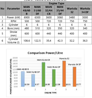
14 Table 3.6 Engine specifications of MAN 48/60 B, MAN 51/60 DF, MAN 32/44 CR, MAN
35/44 DF, Wartsila 32 and Wartsila 34 DF
No Parameter
Engine Type MAN 48/60 B MAN 51/60 DF MAN 32/44 CR MAN 35/44 DF Wartsila 32 Wartsila 34 DF
1 Power (kW) 6900 6300 3600 3060 3480 3000
2 RPM 500 500 720 720 750 750
3 Cylinder 6 6 6 6 6 6
4 Bore (mm) 480 510 320 350 320 340
5 Stroke
(mm) 600 600 440 440 400 400
6 Cylinder
Volume (l) 108.6 122.5 35.4 42.3 32.2 36.3
Figure 3.2 Result of Power per Cylinder Volume Calculation
Based on the results from figure 3.2 above, thus the magnitude of power reduction per cylinder/swept volume of each engine can be seen in the table 3.7 below.
MAN 48/60 B
MAN 51/60 DF
MAN 32/44 CR
MAN 35/44 DF
Wartsila 32
Wartsila 34 DF
10.59 8.57 16.95 12.06 18.01 13.77
0.00 2.00 4.00 6.00 8.00 10.00 12.00 14.00 16.00 18.00 20.00
1 2 3 4 5 6
15 Table 3.7 Power Reduction of Engine Converted to Dual Fuel Engine
No Engine Converted Power Reduction
1 MAN 48/60 B to MAN 51/60 DF 19.056%
2 MAN 32/44 CR to MAN 35/44 DF 28.87%
3 Wartsila 32 to Wartsila 34 DF 23.53%
To determine the value of power per cylinder volume of engine MAN 6L23/30 A, it should be consider the result of power per cylinder analysis of engine MAN 51/60 DF, MAN 35/44 DF and Wartsila 34 DF. According to figure 3.2 above, the power per cylinder reduction between MAN 35/44 DF and Wartsila 34 DF doesn’t have differences significantly. Comparison power per cylinder of MAN 35/44 DF and MAN 51/60 DF have differences significantly. MAN 35/44 DF have less power, less swept volume, and have a higher RPM compared to MAN 51/60 DF. According to the table 3.7 above, the power per cylinder reduction of MAN 35/44 DF is higher compared to MAN 51/60 DF, it’s means when the power is decrease, the cylinder volume is decrease but the RPM is increase, then the reduction of power per cylinder will increase. Therefore, the power per cylinder reduction of MAN 35/44 DF will be used to calculate the power reduction of engine MAN 51/60 DF. Before calculate the power reduction, it require to calculate the power per cylinder volume of engine MAN 6L23/30 A. The data required to calculate the power per cylinder volume are
Power : 960 kW Cylinder : 6
Bore : 225 mm Stroke : 300 mm
Based on the data above, the power per cylinder volume can be obtained as calculation below
Swept Volume = Bore2 × 0.7854 × Stroke = 0.2252 × 0.7854 × 0.3 = 0.01193 m3
= 11.93 litre
Power per Cylinder = Power⁄number of cylinders = 960 kW⁄6
= 160 kW
16
16 = 13.41 kW⁄litre
Thus, the power per swept volume in the engine modified to dual fuel engine be Power per Cylinder Volume(dual fuel engine)
= Power per Cylinder Volume(diesel engine) × (100 − 28.87)%
= 13.41 kW⁄litre × 71.13% = 9.54 kW⁄litre
According to the project guide of dual fuel engines that already serve as the reference for calculating the power per cylinder, bore dimension is having changes of 30 mm. Therefore, in this thesis, the bore dimensions of the engine being 255 mm. Based on these value, swept volume after engine modified to dual fuel engine will be
Swept Volume = Bore2 × 0.7854 × Stroke = 0.2552 × 0.7854 × 0.3 = 0.01532 m3
= 15.32 litre
Engine power = 𝑃𝑜𝑤𝑒𝑟 𝑝𝑒𝑟 𝑆𝑤𝑒𝑝𝑡 𝑉𝑜𝑙𝑢𝑚𝑒 × 𝑆𝑤𝑒𝑝𝑡 𝑉𝑜𝑙𝑢𝑚𝑒 × 𝑐𝑦𝑙𝑖𝑛𝑑𝑒𝑟 𝑛𝑢𝑚𝑏𝑒𝑟 = 9.54 𝑘𝑊⁄𝑙𝑖𝑡𝑟𝑒 × 15.32 𝑙𝑖𝑡𝑟𝑒 × 6
= 877 kW
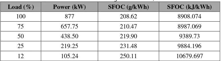
Table 3.8 below shows the engine power in variation loads after the engine modified to dual fuel engine
Table 3.8 Result of Power Reduction of Engine MAN 6L23/30 A at Variation Load
Load (%) Power (kW) SFOC (g/kWh) SFOC (kJ/kWh)
100 877 208.62 8908.074
75 657.75 210.47 8987.069
50 438.50 219.90 9389.73
25 219.25 231.48 9884.196
12 105.24 250.11 10679.697
3.3.2 Specific Fuel Gas Consumption Analysis
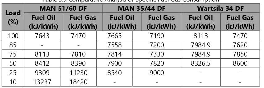
17 natural gas for 6L23 MAN/30 is obtained from comparative analysis of specific fuel gas consumption of engines that already converted to dual fuel engines such as MAN 51/60 DF, MAN 35/44 DF, and Wartsila 34 DF. Table 3.9 below shows the results of a comparative analysis of the specific fuel consumption of those engines
Table 3.9 Comparative Analysis of Specific Fuel Gas Consumption
Load (%)
MAN 51/60 DF MAN 35/44 DF Wartsila 34 DF Fuel Oil (kJ/kWh) Fuel Gas (kJ/kWh) Fuel Oil (kJ/kWh) Fuel Gas (kJ/kWh) Fuel Oil (kJ/kWh) Fuel Gas (kJ/kWh)
100 7643 7470 7665 7190 8113 7470
85 - - 7558 7200 7984.9 7620
75 8113 7810 7814 7330 7984.9 7850
50 8412 8390 7900 7820 8326.5 8600
25 9309 11230 8540 9000 - -
10 13237 18420 - - - -
From the table above, it can be known, at load 50% - 100% specific fuel gas consumption is smaller compared to the specific fuel oil consumption. While at load 10% and 25%, specific fuel gas consumption is greater than specific fuel oil consumption. Percentage change of specific fuel consumption of this engines can be seen in the table 3.10 below.
Table 3.10 Percentage Change of Specific Fuel Gas Consumption
Load (%) Percentage
MAN 51/60 DF MAN 35/44 DF Wartsila 34 DF
100 -2.26 -6.20 -7.93
85 - -4.74 -4.57
75 -3.73 -6.15 -1.69
50 -0.26 -1.01 3.28
25 20.64 5.39 -
10 39.16 - -
18
where this speed is approaching to the speed of engine MAN 6L23/30 A, while the engine speed of MAN 51/60 DF is 500 RPM. Therefore, the result of SFGC of engine MAN 6L23/30 A can be seen in table 3.11 below.
Table 3.11 Result of Total Fuel Gas Consumption Analysis of Engine MAN 6L23/30 A
Load (%) Average Value (%)
MAN 6L23/30 A Fuel Oil
(kJ/kWh)
Fuel Gas (kJ/kWh)
100 -7.065 8908.074 8279
75 -3.92 8987.069 8635
50 2.145 9389.73 9591
The result of specific fuel gas consumption in the table 3.11 above is the total of specific fuel gas consumption (Natural gas consumption + Pilot fuel consumption). Based on MAN B&W project guide, Wartsila project guide and DNV GL, the amount of pilot fuel oil is below 1% of the energy used by the engine. Therefore, the amount of specific fuel consumption of pilot injector and natural gas consumption can be seen in table 3.12 below
Table 3.12 Specific Fuel Consumption of Pilot Injector
Load (%)
MAN 6L23/30 A Total Fuel Gas
(kJ/kWh)
Pilot Fuel (kJ/kWh)
Natural Gas (kJ/kWh)
100 8279 82.79 8196.21
75 8635 86.35 8548.65
50 9591 95.91 9495.09
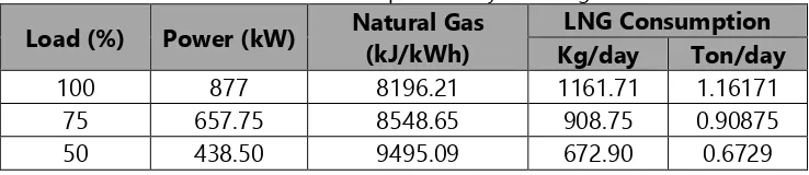
After the specific fuel gas consumption is obtained, the fuel gas consumption at variation loads can be calculated by using formula 3.1 above. Therefore, the result of fuel gas consumption can be seen in table 3.13 below.
Table 3.13 Result of Fuel Gas Consumption Analysis of Engine MAN 6L23/30 A
Load (%) Power (kW) Natural Gas (kJ/kWh)
LNG Consumption Kg/day Ton/day
100 877 8196.21 1161.71 1.16171
75 657.75 8548.65 908.75 0.90875
19
CHAPTER IV
COMPONENT SELECTION OF FUEL GAS SUPPLY SYSTEM
In this chapter will explain how to determine the components of fuel gas supply system, such as LNG storage tank, water spray pump, vaporizer, LNG pump and Gas Valve Unit. All the calculation to determine the requirement of fuel gas supply system can be seen in the explanation below.
4.1 LNG Storage Tank
According to GL rules VI-3-1 Guidelines for the Use of Gas as Fuel for Ships (Germanischer Lloyd, 2010), the LNG storage tank should be an independent tank. lndependent tanks are completely self-supporting and do not form part of the hull structure and it don’t contribute to the hull strength. There are currently three types of independent tank designed for storing LNG in accordance with IMO standards which is Type A, Type B and Type C.
1. Type ‘A’ Tanks
This type of tank is a self-supporting prismatic tank which requires conventional internal stiffening. The maximum allowable tank design pressure in the vapour space for this type of system is 0.7 barg.
Figure 4.1 Type A Independent Tank
Source: International Safety Guide for Inland Navigation Tank-barges and Terminals (OCIMF, 2010)
20
2.2 Type ‘B’ Tanks
The most common arrangement of Type 'B' tank is a spherical tank. Type 'B' tank requires only a partial secondary barrier in the form of a drip tray. The hold space in this design is normally filled with dry inert gas. The maximum allowable tank design pressure in the vapour is, as for Type 'A' tanks, limited to 0.7 barg.
Figure 4.2 Type B Independent Tank
Source: International Safety Guide for Inland Navigation Tank-barges and Terminals (OCIMF, 2010)
Type B tank is not always spherical tank. There is a prismatic type B tank where this tank is improvements of self-supporting tank type A, especially for the construction, supporting structure and isolation system.
2. Type ‘C’ Tanks
Type 'C' tanks are normally spherical or cylindrical with having design pressures higher than 4 barg. Independent tank type C does not require secondary barrier and the hold space can be filled with either inert gas or dry air.
Figure 4.3 Type C Independent Tank
21 According to Wartsila, The standard storage system for transporting various liquid hydrocarbons at low temperatures for several decades has been the IGC (International Gas Carrier) Code Type-C austenitic steel pressure vessels. Therefore, IMO (International Maritime Organization) type C tanks turn out to be the preferred solution for today. Those tanks are very safe and reliable, their high design pressures allow for high loading rates and pressure increase due to boil-off, finally they are easy to fabricate and install. The design pressure of LNG tank type-C range from 4-9 bar. The major disadvantage is the space consumption of this tank type that is restricted to cylindrical, conical and bi-lobe shape. In addition to the unfavourable LNG density these tank shapes lead to a total factor of 3 to 4 times the oil bunker tank volume to carry the same energy in LNG. On top of that, high design pressures reduce the allowable maximum filling limits, if following today’s status of regulation. There are three types of LNG storage tank type C, such as:
4.1.1 Double Walled Fuel Storage Tank
Inner tank: IMO ”type C” tank design. Class acceptance of bottom pipe
connection
Outer tank: function of secondary barrier, creating a double containment system
Capacity range from 30-1000m³
Tank design pressure range from 8.5-9 bar
Layer Insulation (MLI) / Vacuum
Inner/outer vessels manufactured in austenitic stainless steel or 9% Ni steel
Tank Saddles & Tank Connection Space directly attached to the outer tank
22
4.1.2 Single Walled Fuel Storage Tank
IMO ”type C” tank design. All pipe connections above maximum liquid
level
Capacity range from 600-2500 m³
Tank design pressure range from 4-6 bar
Tank material: austenitic stainless steel or 9% Ni steel
Polyurethane insulation
Tank Connection Space separated from Tank
Dome on top of Tank for all tank pipe connections
Figure 4.5 Single Walled Fuel Storage Tank
Source: Gas Storage and Supply System (Piero Zoglia, 2013)
4.1.3 ISO (International Organization for Standardization) Marine Type LNG Container
ISO containerized LNG tank, specifically designed for marine applications
Every container is docked in a dedicated “docking station”, designed for
multiple, horizontal and vertical stacked container arrangements
Each ISO LNG container is equipped with its own process and safety equipment, meeting classification requirements
Figure 4.6 LNG Container Tank
23 4.1.4 LNG Tank Selection
Tank selection is based on the calculation of fuel consumption per day, it can be seen in the table 4.1 below. In this thesis, the capacity of LNG tank that will be designed is for endurance of one week (5 days), which means LNG tank should be able to serve the demands of fuel engine for one week (40 hours of engine operation). The type of the tank that will be selected is container tank because it has advantages as described above and also has a tank capacity of small-sized, therefore in this study allows to choose a type of tank container. The demand of fuel engine per week can be seen in table 4.1 below. This calculation is based on data actual of the engine operation.
Table 4.1 Daily and Weekly Fuel Oil and LNG Consumption
LOAD DAILY CONSUMPTION WEEKLY CONSUMPTION
100 %
MDO LNG MDO LNG
𝑚3 Litre 𝑚3 Litre 𝑚3 Litre 𝑚3 Litre
1.798 1798 2.5816 2581.6 8.99 8990 12.908 12908 Table 4.1 above shows the demand of fuel oil consumption in one week of 8990 litre, and the demand of LNG consumption in one week of 12908 litre. This result is to be considered for selecting the tank type. According to the description above, LNG tank has 3 types, such as Double Walled Fuel Storage Tank, Single Walled Fuel Storage Tank, and ISO Marine Type LNG Container. Based on the calculation result above, the LNG tank that will be selected is ISO Marine Type LNG Container because container tank having a small size of tank volume compared to single and double walled fuel storage tank. Single walled storage tank has capacity range from 30-1000 m³ and double walled storage tank has capacity range from 600-2500 m³. Therefore, it is not possible to install single and double walled storage tank because based on the calculation result, the engine only need 12.908 m³ in a week. The tank selected can be seen in figure 4.7 below.
24
Table 4.2 LNG Tank Specification
Specification Horizontal Cryogenic Tank
Series 2200 H
Model LC16H22-P
Design Temperature -196 ℃
Volume 15.7 m3
Length 7.595 m
Width 2.2 m
Total Height including vent pipe 2.45 m
Design Pressure 5 Bar
Stored Liquid Weight at 95% 6.9 Ton
The selected tank is horizontal cryogenic tank type LC16H22-P with capacity 15.7 m³. It mean this type of tank is able to serve the demand of engine operation for a week. According to the calculation result, the demand of LNG for a week is 12.908 m³. The LNG fuel tank container is fitted with process equipment, namely the valves and instruments required for operational and safety purposes. The LNG fuel tank container is also fitted with a pressure build-up evaporator (PBE) for building up and maintaining an operational pressure of approximately 5 bar in the tank. The detail safety aspects of LNG tank type LC16H22-P will be explained in chapter V.
4.2 Water Spray Pump
Water spray pump should be installed for supplying water to water spray system. This system is for cooling and fire prevention of storage tank. According to GL VI-3-1, Section 3, 3.3.2.2, the system should be designed to cover all areas with an application rate of 10 l/min/m2 for horizontal projected surfaces and 4 l/min/m2 for vertical surfaces. In this thesis, the application rate that will be used is 10 l/min/m2 because the type of the tank is horizontal tank. Therefore, the water spray pump capacity and the diameter pipe of water spray system can be seen in the following calculation.
C = 10 l/min/𝐦𝟐×𝐀𝐓𝐚𝐧𝐤 (4.1) Where
ATank = Surface Area of LNG tank (m2)
= 63.31 m2
C = 10 l/min/m2× 63.31 m2 = 633.1 litre/min
25 = 0.01056 m3/s
The following formula can be used for determining the diameter of the pipe. C = A × v (4.2) Where
C = Capacity m3/h
A = The area of the pipe (m2) v = Velocity, 1 m/s (Assumed) So,
A = C v⁄
= 0.01056 m3/s ⁄1 m/s = 0.01056 m2
A = 𝜋 × 𝑑2⁄4 d = √4𝐴 𝜋⁄
= √4 × 0.01056 3.14⁄ = 0.116 m
= 116 mm
After the calculation of pipe diameter is done, it's used to find the specification on DIN catalogue. Therefore, the selected types of galvanised carbon steel pipe based on DIN standard is
Inside diameter : 133.1 mm Wall thickness : 5.4 mm Outside diameter : 138.5 mm Nominal diameter : DN 125
Based on the calculation result above, the specification of water spray pump can be seen in table 4.3 below
Table 4.3 Specification of Water Spray Pump Manufacturer Evergush
Type XA50/26
Flow Rate Capacities
C 38 m3/h
Head 19.8 m
Speed 1450 rpm
26
26 Dimensions
Length 460 mm
Height 405 mm
Width 320 mm
Weight 101 kg
4.3 Vaporizer
In changing the LNG phase from liquid to gas, vaporizer equipment is required. Vaporizer is a heat exchange medium from liquid to gas where the heat source can be produced from the engine fresh water cooling, exhaust gas, and electric systems. In this thesis, that three systems will be compared. Calculation of capacity of a heat exchanger based on the energy required for changing the LNG phase from liquid to gas, the energy calculation is using the formula 4.3 below
𝐐 = 𝐦 . 𝐂𝐩 . (𝐓𝟐− 𝐓𝟏) (4.3) Where:
Q = Heat energy (Joules) (Btu),
m = Mass of the substance (kilograms) (pounds),
Cp = Specific heat of the substance (J/kg°C) (Btu/pound/°F),
T2− T1= The change in temperature (°C) (°F)
The first step to calculate the heat energy is determining the value of the mass of the substance or mass of LNG. The demand of LNG in one day is 1161.71 kg. These values can be seen in the calculation of the fuel gas consumption. The fuel gas consumption per hour is required for determining the capacity of heat exchanger, therefore the fuel gas consumption per hour is
m = 1161.71 kg/day m = 1161.71 kg/day
8 h
= 145.214 kg/h
* In one day, the engine only operate in 8 hours.
27 calculation should consider the LNG phase from liquid to gas. Figure 4.8 below shown the LNG phase diagram.
Figure 4.8 LNG Phase Diagram
The following is a calculation of the energy for the LNG phase change from liquid to gas
Q1 = 145.214 kg/h × 2.207 kJ/kg K × (111.15 − 91.15) K
Q1 = 6409.746 kJ/h
QL= m × L
QL= 145.214 kg/h × 0.1294 kJ/kg
QL= 18.79 kJ/h
Q2= 145.214 kg/h × 3.512 kJ/kg K × (303.15 − 111.15) K
Q2= 97918.38 kJ/h
So the total energy needed to change the phase of the LNG from liquid to gas are as follows
QTotal= Q1+ QL+ Q2
QTotal= 6409.746 kJ/h + 18.79 kJ/h + 97918.38 kJ/h
QTotal= 104346.916 kJ/h
QTotal= 28.98 kW
28
28 Table 4.4 LNG Consumption
Loads kg/day 𝐦𝟑/day kg/h 𝐦𝟑/h
100% 1161.71 2.58 145.214 0.323
75% 908.75 2.02 113.60 0.253
50% 672.90 1.50 84.113 0.188
Table 4.5 Natural Gas Consumption
Load kg/day 𝒎𝟑/day kg/h 𝒎𝟑/h
100% 697026 1548 87128.25 193.50
75% 545250 1212 68156.25 151.50
50% 403740 900 50467.50 112.50
In this thesis, there are 3 systems that will be discussed for the LNG regasification, such as circulating water vaporizer, steam vaporizer, and electric vaporizer. The results of these three systems will be compared to choose the most appropriate system.
The steam vaporizer is uses steam as thermal source. The steam is passing through the outer tube bundles to release heat, and LNG is flowing in the tubes to absorb heat to produce natural gas. The merits of this vaporizer are the compacted construction, higher efficiency, better reliability, temperature controlled easily, and the demerits are the steam source supplied, the higher costs of original invest and operation. This vaporizer often used in LNG carrier ship.
Water circulation vaporizers are self-controlling and do not require any external, expensive flow control devices, temperature monitors or control devices. It is the ultimate, reliable, cost effective, economic solution for simple gas vaporization. The design matches the flow rate of the available water to the required maximum vaporization heat load, ensuring full vaporization of the incoming cryogen with a reasonable gas exit temperature. The water flow rate becomes a fixed parameter simplifying the operating controls. Even if the cryogen flow reduces, full vaporization is achieved and the gas exit temperature approaches closer to the incoming water temperature, but still a value acceptable to the process, since it cannot be higher than the water temperature.
29 vaporizer are the heater elements are easily removable and replaceable without affecting the integrity of the vaporizer construction. Low pressure drops are attainable along with effective hear transfer rates. The units are lightweight, portable and require a smaller footprint than comparable models. The vaporizer electrical control design comprises a solid state temperature controller, independent auto resetting over temperature switch controller and a separate manual resetting high limit shutdown controller. The disadvantages of electric vaporizer are high power cost to operate and possible limitation in available power.
According to explanation above, circulating water vaporizer will be applied to the fuel gas system because it’s more profitable compared to steam vaporizer and electric vaporizer. Circulating water vaporizer has a lower cost operation and only need hot water as a source to vaporize LNG. The hot water can be obtained from engine cooling water system. The temperature of water from engine cooling system can be seen in table 4.6 below.
Table 4.6 Water Temperature of Engine Cooling System
Cylinder
Temperature (℃)
Load 12% Load 25% Load 50% Load 75% Load 100%
Cylinder 1 74.8 74.7 74.5 75 76
Cylinder 2 75.2 75.3 75 75.7 76.8
Cylinder 3 75.5 75.5 75.3 76 77.2
Cylinder 4 75.2 75.3 75 75.7 76.8
Cylinder 5 74.8 74.7 74.5 75 76
Cylinder 6 91.8 92.5 92.3 93.5 86.9
Based on the water temperature of engine cooling system above, the average of water temperature of load 12% to 100% is 77,8 ℃ until 78,5 ℃. The vaporizer capacity should be able to supply the gas fuel during maximum load. Based on calculation results, the required gas flow rate in 100% load is 145.214 kg/h. The selected vaporizer is shown in table 4.7 below.
Table 4.7 Specification and Dimension of Circulating Water Vaporizer Vaporizer Type Circulating Water Vaporizer
Model VWB-400
Specification
LNG Flow rate 400 kg/hr
30
30 Dimensions
Length 0.45 m
Width 0.65 m
Height 2.24 m
Weight 275 kg
According to the specification above, the circulating water vaporizer type VWB-400 can serve the required fuel gas, where the demand of fuel gas in 100% load is 145.214 kg/h. In 100% load of engine operation, the water flow rate of engine water cooling system is 40.4 m3/hr. This value is based on the data retrieval of engine type 6L23/30 A. It’s mean the engine can serve the required water flow rate of circulating water vaporizer type VWB-400 where this type of vaporizer only need 5.1 m3/hr of water flow rate to vaporize the LNG.
4.4 LNG Pump
LNG pump is required to transfer LNG from storage tank to vaporizer. The LNG pump should be able operate in maximum pressure of LNG and can operate in low temperature, where the temperature of LNG is -182 ℃. The capacity of LNG pump is determined by engine fuel gas requirement. Based on the calculation of LNG consumption, the LNG flow rate at maximum load is 0.323 m3/h or 5.383 l/min. Therefore, the selected LNG pump should be able operate in 5.383 l/min, it can be seen in table 4.8 below
Table 4.8 Specification and Dimension of LNG Pump Manufacturer Vanzetti
Type VT-1 32 25
Flow Rate Capacities
𝑪𝒎𝒊𝒏 −𝒎𝒂𝒙 1.4 – 8.1 lpm
Power Installed 3 - 15 kW
Dimensions
Length 1950 mm
Height 1150 mm
Width 860 mm
Weight 420 kg
4.5 Gas Valve Unit
31 to the engine, and to ensure a fast and reliable shut down of the gas supply. The GVU include a gas pressure control valve and a series of block and bleed valves to ensure reliable and safe operation on gas. The unit includes a manual shut-off valve, inert gas connection, filter, fuel gas pressure control valve, shut-off valves, ventilating valves, pressure transmitters/gauges, a gas temperature transmitter and control cabinets.
Wartsila provides two different types of gas valve unit. One is the gas valve unit open design (GVU-OD, see figure 4.10) which requires installation in an explosion-proof gas valve unit room and airlock is required between GVU room and surrounding space. The other is gas valve unit enclosed design (GVU-ED, see figure 4.9). The gas valve unit enclosed design is a solution where all the equipment is mounted inside a gas tight casing. The GVU with gas tight casing enables the installation of the gas control system directly next to the engine in the engine room (safe area). In this case, the cover acts as the double wall and thus provides for a secure enclosure of the gas control system. This will safely prevent the gas from getting into the safe area in the event of a gas leak in the gas control system. This arrangement allows the GVU-ED to be placed inside the engine room to minimise installation costs. [11]
Figure 4.9 Gas Valve Unit Enclosed Design
Source: Dual Fuel Engine Development and Design (Mika Ojutkangas, Wartsila)
Figure 4.10 Gas Valve Unit Open Design
32
32 Because of some considerations, in this thesis, GVU enclosed design will be installed because the engine room in the laboratory doesn’t has enough space to install GVU open design. The selected GVU is referenced from Wartsila 50 DF product guide, where it’s provides two kinds of gas valve unit enclosed design, as shown in table 4.9 below.
Table 4.9 Types of Gas Valve Unit Enclosed Design Source: Wartsila 50 DF Project Guide
Pipe Connection GVU DN80 GVU DN100
Gas Inlet DN80 / DN125 DN100 / DN150
Gas Outlet DN80 / DN125 DN100 / DN150
In this thesis, the selected GVU is GVU DN 100 because the result of pipe diameter calculation of fuel gas system is 151.4 mm or DN150, it showed in table 4.11 below. The dimension of selected GVU can be seen in table 4.10 below.
Figure 4.11 Design of GVU-ED Source: Wartsila 50 DF Project Guide
Table 4.10 Dimension of Gas Valve Unit Enclosed Design Source: Wartsila 50 DF Project Guide
Manufacturer Wartsila
Type GVU DN100
Dimensions
Height 2710 mm
Width 3200 mm
33 4.6 Pipe Diameter Calculation
Pipe diameter depends on flow rate and velocity. This pipe diameter calculation is based on the fuel oil consumption per hour of the engine and it’s required to select the dimensions of gas valve unit. There is a different pipe diameter between LNG tank to vaporizer and vaporizer to main engine because fuel phase between LNG tank and vaporizer still in liquid phase while the fuel phase between vaporizer and main engine is in gas phase. The calculation of pipe diameter is using formula as
C = v × A (4.4) Where,
C = LNG and Gas consumption rate (m3⁄s) = 0.323 m3⁄h , for liquid phase
= 193.50 m3⁄h, for gas phase v = LNG and Gas velocity (m s⁄) A = Pipe surface area (m2)
According to Wartsila 50 DF project guide pages 36, the maximum velocity of LNG is 3 m s⁄, while the maximum velocity of gas is 20 m s⁄. Therefore, in this thesis, the velocity of LNG assumed of 1 m s⁄ and for gas velocity assumed of 3 m s⁄. The result of pipe diameter can be seen in the table 4.11 below
Table 4.11 Pipe Diameter Calculation Result
No Phase Pipe Diameter
1 Liquid Phase 10.7 mm
2 Gas Phase 151.4 mm
After the calculation of pipe diameter is done, it’s required to consider the selection of pipe based on the regulation. According to GL rules VI-3-1 section 2.2, the material of gas piping should be accordance with GL rules I-1-6 section 6, where the pipe should be seamless and welded, and should be containing with 9% nickle steel, austenitic steel, and aluminium alloys.
In this thesis, the selected pipe is seamless and welded steel pipe from FW Fernwarme Technik GmbH manufacturer. This pipe is approved by ASTM A 312 material TP316/ TP316L, dimensions according to ASME B 36.19M/B 36.10M or EN 10216-5/ EN10217-7, 1.4401/1.4404, dimensions according to EN ISO 1127 with acceptance test certificate in accordance with DIN EN 10204/3.1.
34
34 Selected pipe for liquid phase
35
CHAPTER V
DESIGN ARRANGEMENT
5.1 Fuel Gas Supply System
Gas fuel supply system is a system which designed to fulfil engine required when engine operated in variation load. In this thesis, the demand of fuel gas in variation load has been calculated.
Process of gas supply system is started from LNG storage tank where natural gas is in liquid phase. LNG will be transported to vaporizer by using low pressure pump. The capacity of LNG pump is based on gas engine required per hour. Vaporizer type that will installed in this thesis is the result of comparison between circulating water vaporizer, steam vaporizer and electric vaporizer. In the outlet of vaporizer, natural gas have phase changed from liquid into gas phase.
Before gas flowing to engine, previously gas will through gas valve unit (GVU) where GVU will regulate the pressure and temperature of gas. In every connection in the open spaces will use a double pipe flowline.
36
36 5.2 Design Requirement
5.2.1 LNG Storage Tank GL VI-3-1, Section 2, 2.8.1.1
The storage tank used for liquefied gas should be an independent tank designed in accordance with GL Rules, Liquefied Gas Carriers (I-1-6), Section 4.
GL I-1-6, Section 4, 4.2.4
Independent tanks are self-supporting; they do not form part of the ship's hull and are not essential to the hull strength. There are three categories of independent tanks.
Type A independent tanks are tanks which are designed primarily using classical ship-structural analysis procedures. The design vapour pressure P0 is to be less than 0,7 bar.
Type B independent tanks are tanks which are designed using model tests, refined analytical tools and analysis methods to determine stress levels, fatigue life and crack propagation characteristics. The design vapour pressure P0 is to be less than 0,7 bar.
Type C independent tanks (also referred to as pressure vessels) are tanks meeting pressure vessel criteria.
GL VI-3-1, Section 2, 2.8.1.2
Pipe connections to the tank should normally be mounted above the highest liquid level in the tanks. However, connections below the highest liquid level may be accepted after special consideration by the Administration.
GL VI-3-1, Section 2, 2.8.1.3
Pressure relief valves as required in the GL Rules, Liquefied Gas Carriers (I-1-6), Section 8 should be fitted.
GL VI-3-1, Section 2, 2.8.1.3
The outlet from the pressure relief valves should normally be located at least B/3 or 6 m, whichever is greater, above the weather deck and 6 m above the working area and gangways, where B is the greatest moulded breadth of the ship in metres. The outlets should normally be located at least 10 m from the nearest:
1. Air intake, air outlet or opening to accommodation, service and control spaces, or other gas safe spaces; and
37 GL VI-3-1, Section 2, 2.8.1.3
Storage tanks for liquid gas should not be filled to more than 98 % full. GL VI-3-1, Section 2, 2.8.1.3
Gas in a liquid state may be stored in enclosed spaces, with a maximum acceptable working pressure of 10 bar.
5.2.2 Gas Piping System GL VI-3-1, Section 2, 2.5.17
Gas piping should not be led through other machinery spaces. Alternatively, double gas piping or a ventilated duct may be approved, provided the danger of mechanical damage is negligible, the gas piping has no discharge sources and the room is equipped with a gas alarm.
GL VI-3-1, Section 2, 2.5.18
An arrangement for purging gas bunkering lines and supply lines (only up to the double block and bleed valves if these are located close to the engine) with nitrogen should be provided.
5.2.3 System Configuration GL VI-3-1, Section 2, 2.6.2.1
All gas supply piping within machinery space boundaries should be enclosed in a gas tight enclosure, i.e., double wall piping or ventilated ducting.
GL VI-3-1, Section 2, 2.6.2.2
In case of leakage in a gas supply pipe making shutdown of the gas supply necessary, a secondary independent fuel supply should be available.
GL VI-3-1, Section 2, 2.6.2.2
Gas supply piping within machinery spaces may be accepted without a gastight external enclosure on the following conditions
1. Pressure in gas supply lines within machinery spaces should be less than 10 bar, e.g., this concept can only be used for low pressure systems. 2. A gas detection system arranged to automatically shut down the gas
38
38 5.2.4 Gas Supply System in gas machinery spaces
GL VI-3-1, Section 2, 2.7.1.1
Gas supply lines passing through enclosed spaces should be completely enclosed by a double pipe or ventilated duct. This double pipe or ventilated duct should fulfil one of the following:
1. The gas piping should be a double wall piping system with the gas fuel contained in the inner pipe. The space between the concentric pipes should be pressurised with inert gas at a pressure greater than the gas fuel pressure. Suitable alarms should be provided to indicate a loss of inert gas pressure between the pipes. Alternative arrangements like monitored evacuated double wall pipes can be accepted by GL. When the inner pipe contains high pressure gas, the system should be so arranged that the pipe between the master gas valve and the engine is automatically purged with inert gas when the master gas valve is closed 2. The gas fuel piping should be installed within a ventilated pipe or duct.
The air space between the gas fuel piping and the wall of the outer pipe or duct should be equipped with mechanical under pressure ventilation having a capacity of at least 30 air changes per hour. This ventilation capacity may be reduced to 10 air changes per hour provided automatic filling of the duct with nitrogen upon detection of gas is arranged for. The fan motors should comply with the required explosion protection in the installation area. The ventilation outlet should be covered by a protection screen and placed in a position where no flammable gas‑air mixture may be ignited.
GL VI-3-1, Section 2, 2.7.1.2
The connecting of gas piping and ducting to the gas injection valves should be so as to provide complete coverage by the ducting. The arrangement should facilitate replacement and/or overhaul of injection valves and cylinder covers. The double ducting should be required also for gas pipes on the engine itself, and all the way until gas is injected into the chamber.
5.2.5 Ventilation system GL VI-3-1, Section 2, 2.10.1.1
39 GL VI-3-1, Section 2, 2.10.1.3
Any loss of the required ventilating capacity should give an audible and visual alarm at a permanently manned location.
GL VI-3-1, Section 2, 2.10.1.8
The required capacity of the ventilation plant is normally based on the total volume of the room. An increase in required ventilation capacity may be necessary for rooms having a complicated form.
GL VI-3-1, Section 2, 2.10.1.9
Non-hazardous spaces with entry openings to a hazardous area should be arranged with an air‑lock and be maintained at overpressure relative to the external hazardous area.
5.2.6 Safety Functions of Gas supply system GL VI-3-1, Section 5, 5.6.1
Each gas storage tank should be provided with a tank valve capable of being remote operated and is to be located as close to the tank outlet as possible. GL VI-3-1, Section 5, 5.6.2
The main gas supply line to each engine or set of engines should be equipped with a manually operated stop valve and an automatically operated “master gas fuel valve” coupled in series or a combined manually and automatically operated valve. The valves should be situated in the part of the piping that is outside machinery space containing gas fuelled engines, and placed as near as possible to the installation for heating the gas, if fitted.
GL VI-3-1, Section 5, 5.6.3
Each gas consuming equipment should be provided with a set of “double block and bleed” valves, so that when automatic shutdown is initiated as given in Table below, this will cause the two gas fuel valves that are in series to close automatically and the ventilation valve to open automatically.
GL VI-3-1, Section 5, 5.6.3.1
40
40 GL VI-3-1, Section 5, 5.6.5
There should be one manually operated shutdown valve in the gas supply line to each engine upstream of the double block and bleed valves to assure sa