Distribution Temperature of Analysis on CH
4
-CO
2
Gas
Mixed in Double Pipe Heat Exchanger by Controlled
Feeze Out Area Methode
Fatma Y. Hasyim, Novi E. Mayangsari, and Sumarno Material of Laboratory
Chemical Engineering Department, Faculty of Industry Technology, Sepuluh Nopember Institut of Technology Surabaya Jl. Arief Rahman Hakim, Surabaya INDONESIA
Abstract :
The research purpose to get the temperature distribution on CH4-CO2 gas mixture in the annulus double pipe heat exchanger and position of
formation CO2 frozen from end input the double pipe heat exchanger. Controlled freeze out area method using a heat exchanger in this
research uses four steps, such as, flushing impurities, start-up equipment, the proses of freezing CO2, sampling CH4-CO2 output from double
pipe heat exchanger and sampling CO2 frost in double pipe heat exchanger. CH4-CO2 gas mixture and carbon dioxide out from heat
exchanger is analyzed by using Gas Chromatography (GC). The data get in this research is distribution temperature of CH4-CO2 gas mixture,
wall temperature and nitrogen along the double-pipe heat exchanger in which to solve these two temperatures simultaneously using MATLAB software with Newton Rhapson and Runge Kutta order 4. The results of analysis Gas chromatography shown in CH4 5% CO2 with
pressure of 1, 5, 10, and 20 bar most produced yield of CH4 99% mol so that This indicates that the purification of CH4 has been successful
although there are still a small percentage of CO2 in it.
Keywords : CO2 removal, controlled freeze out area, carbon dioxide (CO2), cryogenic, heat exchanger
1. Introduction
Natural gas is a mixture of hydrocarbon compounds that have a very high boiling point, so that at atmospheric pressure and room temperature that form of a gas (except C5 +). The mixture is usually composed of
methane, ethane, propane, butane, pentane, and a small amount of hexane, heptane, octane, and the heavier fraction. Natural gas components, indicating that methane is the largest component of the gas mixture. Inorganic components such as nitrogen, hydrogen sulfide, carbon dioxide is an undesirable component in the production because it can not generate heat and cause corrosion and other problems that may occur in the process [1]. One advantage of using natural gas compared with other sources of energy that is produced natural gas is more efficient, much more clean and very friendly environment.While in the manufacture of LNG, CO2 gas must be
removed beforehand to prevent freezing at extremely low temperatures [2]. Because natural gas liquefaction process is running at very low temperatures (-161oC), while the freezing point of CO2 around -78.4 ° C [3].
There are several methods that can be used to eliminate the CO2 content. Some of the latest methods being
developed or have been performed testing the feasibility of a small scale (Pilot Project) and has even been used to eliminate the CO2 content. Some methods such as amine absorption, membrane, PSA (pressure swing adsorbtion),
controlled freeze zone (CFZtm), and controlled freeze out area using a heat exchanger.
The basic concept of controlled freeze out area is to remove CO2 by utilize the phase change from gas to solid
(CO2 frost) with cryogenic in heat exchanger without an additional tool. This process does not require
high-pressure such as distillation, but operate at atmospheric high-pressure. In addition, this method does not require a large surface area such as adsorption, because deposition of CO2 based on direct phase change from gas to solid [4]. In 2009, Chang et al studied temperature distribution with the effect of composition CO2 and pressure.
Phenomenon that occurs in heat exchanger is not known when using different of CO2 concentrations. Therefore,
needed research further on temperature distribution in CH4-CO2 mixtures at various concentrations of CO2 and gas
mixture pressure.
2. Material and Methods
a. CH4-CO2 gas mixture (PT Samator)
b. 99% HP nitrogen gas as flushing and sampling (PT Samator)
c. 99% liquid nitrogen as start-up and freezing CO2 process (PT. Samator)
d. 40% volume solution of ethylene glycol as an anti freeze e. Aquades
2.2. Variables of research
a. Comparison of CO2: CH4 gas mixture = 5% CO2 (mol/mol)
b. Pressure of CO2 - CH4 gas mixture = 1, 5, 10, and 20 bar
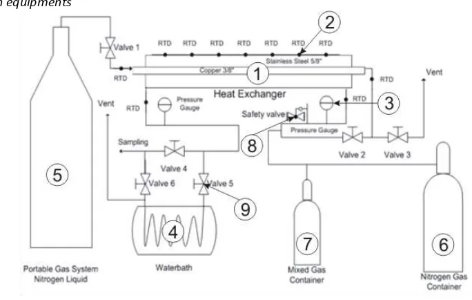
2. 3. Research equipments
Figure 1. Tool of Temperature Distribution CO2 frost Process
Description:
1. Double pipe heat exchanger
2. RTD (Resistance Temperature Detector)
3. Pressure gauge
4. Water bath heater
5. Tangki N2 liquid
6. Tangki N2 gas
7. Tangki campuran gas CH4-CO2
8. Safety valve
9. Valve
2. 4. Procedures of Research
Preparation of reactant
CH4-CO2 gas mixture with gas ratio of CO2 to CH4 gas mixture = 5% CO2 (in mole ratio) that has been provided
by PT. Samator.
Experiment
The procedure of this study consists of 4 stages: Stage I : Flushing impurities
Stage I aims to eliminate impurities such as air, CO2 and H2O which there in the Figure 1
research equipment. Stage II : Start-up equipment
(a) (b) Stage III : Freezing CO2 Process and sampling of CH4 gas output double pipe heat exchanger
Stage III aims to test cryogenic so get CO2 frost which contained Figure 1 research equipment.
Stage IV : Sampling of CO2 Frost in Double Pipe Heat Exchanger
Stage IV aims to Determine the concentration of CH4 in the CO2 frost which contained Figure 1
research equipment.
The above research was repeated with feed of CH4-CO2 gas mixture pressure at 1, 5, 10, and 20 bar with
composition of different CO2 that is equal to 5% CO2.
3. Results And Discussions
Analysis of temperature distribution CH4-CO2 gas mixture in double pipe heat exchanger using controlled
freeze-out area (CFO-area) method has been performed. In CFO-area technique, CH4-CO2 gas mixture at room
temperature through the annulus and N2 gas at cryogenic temperatures through the tube, where each flow of gas
in counterflow. Then CO2 gas in CH4-CO2 gas mixture freeze, based on data from distribution of temperature can
know the position of formation CO2 frost in annulus double-pipe heat exchanger. The position of formation CO2
frost has been predicted previously from temperature of CO2 frost based on HYSYS v7.0 which contained Table 1.
Tabel 1. Pridicted Data temperature of CO2 frost based on HYSYS v7.0
Composition of CO2 Pressure (bar) Freezing of CO2 Temperature (K)
5%
1 163,60
5 178,15
10 184,43
20 190,32
In Table 1 show that temperature CO2 frost will be increase at the higher of pressure and composition. It
based on the ideal gas equation PV = nRT where if composition and pressure increases, temperature of CO2 frost
will increase too. In addition, CO2 frost temperature data in Table 1 are also used as reference for prediction
position of the formation CO2 frost while experiment. In this study, get temperature CH4-CO2 gas mixture data
along double pipe heat exchanger. From temperature gas mixture can be known temperature outer wall tube and temperature N2 along double pipe heat exchanger. The method used to solve the equations used is Newton
Rhapson and Runge Kutta order 4 simultaneously using MATLAB software.
3.1 Distribution of temperature on CH4-CO2 gas mixture
Of the two methods above, obtained temperature of outer wall tube double-pipe heat exchanger and temperature of gas N2 liquid, which can be described profile temperature distribution in double-pipe heat
exchanger. Temperature distribution profiles can be obtained from the change in temperature of CH4-CO2 gas
(c) (d)
(c) (d)
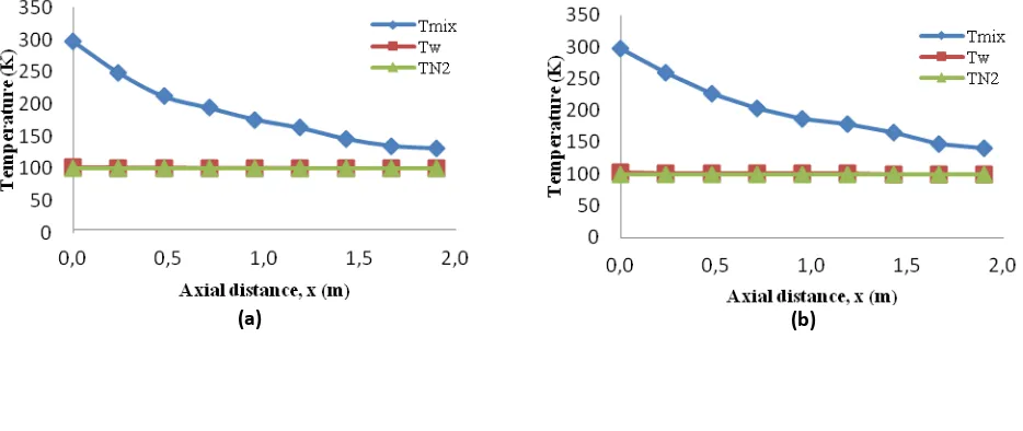
Figure 2. Temperature distribution of CH4-CO2 gas mixture at the composition of 5% CO2 and various pressures: (a) 1 bar, (b) 5
bar, (c) 10 bar, and (d) 20 bar
In Figure 2, show that temperature of outer wall tube approaches temperature of N2 because the tube
has a thin thickness so that it has a small thermal resistance. In the Figure shows that the temperature of N2 lower
than temperature of outer wall tube. This happens because the part of the outer tube wall related to the temperature of CH4-CO2 gas mixture which has higher temperature than temperature of gas N2 liquid. With the
same composition at lower pressure so the positions formation of CO2 frost farther from the end of entrance CH4
-CO2 gas mixture and temperature of CO2 frost the lowest. In Table 1, with a higher composition of CO2 and
increasing pressure resulted temperature the formation of CO2 frost will be higher and the position formation of
CO2 frost closer to the end of the entrance of CH4-CO2 gas mixture. This is consistent with the ideal gas equation
PV = nRT, where the composition and pressure is proportional to the temperature of CO2 frost.
3.2. Determination the position formation of CO2 frost
Freezing point is the axial location where the partial pressure of CO2 equal to saturation pressure
(sublimation) on the wall, because the wall temperature is always lower than the average temperature of the gas mixture (Chang et al, 2009). The position of CO2 frost each variable on CO2 compositions and pressures different.
CO2 reach that is the point of sublimation will change into a solid so that the composition of CO2 in the gas phase
would decrease as a result of solidification, and pure solid fraction only consists of CO2 ice or CO2 frost without the
presence of CH4 in that solid composition.
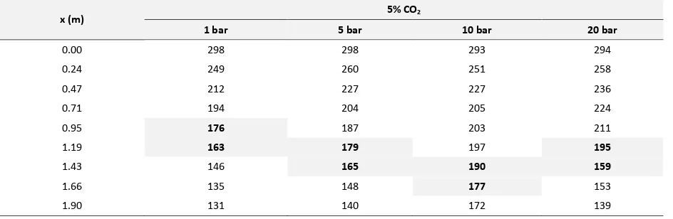
Table 2. Temperature data of CH4-CO2 gas mixture along the double-pipe heat exchanger
x (m)
Table 2 can be used as a reference in prediction temperature and position CO2 frost based on temperature of
CH4-CO2 gas mixture in Table 2. This prediction is seen when the temperature of CH4-CO2 gas mixture is lower than
or equal to the temperature of CO2 frost. Thus, the position of CO2 frost could occur in each part along double-pipe
4. Conclusion
Based on the results and discussion, it can be concluded:
1. The measurements results of temperature of CH4-CO2 gas mixture along annulus double pipe heat
exchanger can be used as a prediction of the position formation CO2 frost.
2. With composition and pressure of the higher will be cause temperature in the formation CO2 frost higher
so that the position formation CO2 frost is getting closer to the end of entrance CH4-CO2 gas mixture.
Acknowledgments
Authors are aware of the report will not be completed without the assistance of various parties. Therefore, on this occasion the authors wish to thank both our parents, our brothers, Mr. Professor. Dr. Ir. Tri Widjaja, M.Eng. as Chairman of the Department of Chemical Engineering, Dr.Ir. Kuswandi, DEA as the secretary of the Department of Chemical Engineering-ITS FTI, setiyo Gunawan, ST., PhD. as coordinator of the Final Project and Thesis Department of Chemical Engineering-ITS FTI, Mr. Dr. Ir. Sumarno, M.Eng, as Supervisor and Head of Materials Technology Laboratory, for their guidance and advice given, Lecturer guardians, Mr. and Mrs. teaching experience, crew polymer friends, friends of 2008, and all those who helped in Full Paper do this.
References
[1] Tolage, J., 200 , E e gi E uity Epi .
[2] Ka toha djo o, “.; A gga a; “u ihi; Yulius a , , 200 A so si CO2 dari Campurannya dengan CH4 dan N2 Melalui
Ko takto Me a “e at Be o gga Me ggu aka Pela ut Ai , Depa te e Tek ik Ki ia, U ive sitas I do esia, Jaka ta.
[3] Pe y, R. H.; G ee , D. W., 200 , Pe y’s Che i al E gi ee ’s Ha d ook , A e i a.