UAV VISUAL AUTOLOCALIZATON BASED ON AUTOMATIC LANDMARK
RECOGNITION
P. Silva Filhoa, E. H. Shiguemoria, O. Saotomeb
a
IEAV - Instituto de Estudos Avanc¸ados, S˜ao Jos´e dos Campos-SP, Brazil - (silvafilho, elcio)@ieav.cta.br b
ITA - Instituto Tecnol´ogico de Aeron´autica, S˜ao Jos´e dos Campos-SP, Brazil - [email protected]
KEY WORDS:ORB, AKAZE, Position, Estimation, GNSS, GPS-denied, Visual navigation
ABSTRACT:
Deploying an autonomous unmanned aerial vehicle in GPS-denied areas is a highly discussed problem in the scientific community. There are several approaches being developed, but the main strategies yet considered are computer vision based navigation systems. This work presents a new real-time computer-vision position estimator for UAV navigation. The estimator uses images captured during flight to recognize specific, well-known, landmarks in order to estimate the latitude and longitude of the aircraft. The method was tested in a simulated environment, using a dataset of real aerial images obtained in previous flights, with synchronized images, GPS and IMU data. The estimated position in each landmark recognition was compatible with the GPS data, stating that the developed method can be used as an alternative navigation system.
1. INTRODUCTION
Unmanned Aerial Vehicles (UAV) is one of the main strategic technologies nowadays due to their high applicability in several areas, such as urban areas and frontiers surveillance (Blumenau et al., 2013); object and landmarks recognition (Zhao et al., 2013); and remote sensing (Pajares, 2015). This popularity grew mostly because of their ability to deploy a mission with little human in-teraction, in other words, their applicability as autonomous sys-tems.
The first aspect for the development of an autonomous system is regarding its navigation control. The navigation consists in obtaining information regarding the flight, the field and the air-craft itself, in order to reach a specific location (Dumble and Gibbens, 2014). Most of the autonomous navigation systems available nowadays use the Inertial Measurement Unit (IMU) and a Global Navigation Satellite System (GNSS), such as the Global Position System (GPS). Even though for most environments the GNSS+IMU navigation works well in clear sky-view, it is not a fully reliable system. Most IMU used in UAV lose precision in a short period of time, so it needs another position estimator, in order to work properly again. The GNSS is an external signal and it can be lost for many reasons such as: satellite disposition; mul-tipath; changes in the Ionosphere and the presence of ionospheric bubbles (Muella, 2008, Takahashi et al., 2015); and jamming or signal blocking (LeMieux, 2012). In such a system, if the GNSS data is lost, the UAV will not work properly and may even cause an accident.
Several works have been developed in order to obtain an alter-native or redundant navigation system for the autonomous nav-igation that could deal with fails in GNSS or in GNSS-denied areas (Rady et al., 2011, Singh and Sujit, 2016). One strong can-didate, which is the subject of this work, is a computer vision system that can estimate the aircraft’s latitude and longitude from images captured and processed onboard during flight.
1.1 Visual Navigation Systems
Nowadays, there are several researches on Visual Navigation sys-tems. Most studies work on ways to develop methods that can
adapt to the multiple circumstances an UAV may face during flight and can affect the visual data obtained: different weather condition; different sensors; time of day; areas over which the aircraft is located; and others. The main strategies applied to the navigation in development nowadays are Visual Odometry (Quist and Beard, 2016), Simultaneous Localization and Map-ping (SLAM) (Azizi et al., 2016), Template Matching (Braga et al., 2015) and Landmark Recognition (DeAngelo and Horn, 2016). Each of them has advantages and drawbacks that must be taken into consideration during development. For example, both Template Matching and Landmark Recognition are more compu-tationally complex and need to know the region of flight a pri-ori, but on the other hand, works implementing them have shown higher precision than works using visual odometry or SLAM. Vi-sual Odometry can be used in unknown areas, but, the same way as an IMU, it accumulates errors throughout the flight. SLAM is one of the most discussed and studied strategy nowadays, but it always needs to fly over previously visited areas, in order to have a precise navigation.
proposed method has been tested in two different experiments: geo-referencing a videoframe using landmark recognition; and estimating an UAV position, in a simulated flight using previ-ously obtained aerial images.
1.2 Related Works
Even though landmark recognition is not a new subject on the literature for autonomous ground vehicles (Farag and Abdel-Hakim, 2004), the approach for aerial navigation systems is not well explored yet, mostly because of its complexity and high real-time requirements on precision and computer processing (Silva Filho, 2016). Because of that high computational costs, there are some works that state the need to send the data to a ground sta-tion, which will process the images, and then send to the UAV only the result of the recognition (Silva, 2015, Michaelsen and Meidow, 2014).
There are several challenges in the recognition process, such as difference in resolution, rotating, translating, scale, luminos-ity, different sensors and many others. Most works on land-mark recognition for aerial navigation takes on the results of al-ready developed object-recognition algorithms and adapt them to the different aerial circumstances. In (Cruz, 2014), His-togram of Gradient (HOG) associated with a Support Vector Ma-chine (SVM), Haar-like feature cascade and Local Binary Pattern (LBP) cascade are all applied to recognize specific classes of ob-jects, such as soccer fields and airports. It is a suitable technique to recognize classes, but the training of the classes is time con-suming. In (Kezheng et al., 2015), the UAV was able to localize an specific artificial landmark (the letter H) for navigation, detect-ing features and corners of the image usdetect-ing the Hough Transform and Labourasse Transform. The project can work on a real-time base, but is limited to recognize a specific artificial landmark. And on (Zhu and Deng, 2016), the landmarks are recognized and a mathematical scheme is proposed for distance and position es-timation for the aircraft. It is still a heuristic proposal without a practical recognition algorithm.
Feature based algorithms, such as Scale Invariant Feature Trans-form (SIFT) (Lowe, 2004), Oriented FAST and Rotated BRIEF (ORB) (Rublee et al., 2011), AKAZE (Alcantarilla et al., 2011), have changed the object recognition field of study (Li et al., 2015). In (Lee et al., 2010) the method first extracts feature points from the image data taken by a monocular camera using the SIFT algorithm. The system selects landmark feature points that have distinct descriptor vectors among the feature points, cal-culate those points location and store them in a database. Based on the landmark information, the current position of the UAV is estimated. It considers as a landmark just the exact feature point instead of an object. This method has been used for indoor ap-plications, which is a controlled environment. In outdoor flights, though, this application could not be used properly because the amount of similar features would result in a high rate of false positive encounters.
2. LANDMARK AND UAV AUTOLOCALIZATION
Finding a suitable and general method for a Landmark Recogni-tion NavigaRecogni-tion System is not a trivial task, mostly because of the recognition aspect. The different conditions in which the land-mark may appear for the system (luminosity, rotation, scale, per-spective, etc) demands a general invariant method that is quite difficult to obtain. In addition to that, there is also the require-ment that the algorithm processes in real-time.
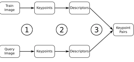
Figure 1. Feature points detection, descriptors extraction and feature matching
This work then, developed a method based on the combination of two well known object recognition methods (Feature Points and Template Matching) in order to obtain an algorithm with a high reliability that can be processed in real-time. In other words, that can provide the UAV position in such a short time, that it will still be a valid position for the autonomous navigation system. After the recognition, it was possible to extract the position information of the aircraft using the position information of the recognized landmark.
2.1 Recognition
Object recognition is a classic visual computer problem, and there are several methods developed. As it needs to be a real-time ap-plication, feature (keypoints) points detection and descriptors ex-traction was selected as the first most suitable strategy. There are several different feature point algorithms in the literature. Some of them were tested before deciding which would work better for the application, and the tests evaluated mostly their reliabil-ity on recognition of the landmarks but also their execution time. ORB, AKAZE, SIFT and SURF were tested. The basic struc-ture of those algorithms is the feastruc-ture point detection in the scale space of the image and the descriptor extraction of each feature point detected. This structure is performed in the image of the landmark that needs to be recognized (this one is called the train image) and in the aerial image captured during flight (the query image). The difference between each feature point algorithm is mostly on the scale-space used (linear or non-linear) and the de-scriptor (binary or non-binary). From the tests, the feature point with better results was AKAZE.
The feature points of each image are then matched based on their descriptors. This matching is then analyzed and graded based on a distance function. The pairs with the lower grades are consid-ered the best matches and they are used to estimate the parame-ters of a General Affine Transform that maps the query image in the train image. A Fuzzy Inference System is then used to vali-date the Affine Transform obtained. Figure 1 shows the matching flow.
At first, only the feature point strategy was used to recognize the landmarks. During tests, it was observed a high number of false positive recognitions, which were not reduced using RANSAC or any other algorithm to reduce the outliers. RANSAC actually just added a higher processing time, with little gain in the reliability of the algorithm.
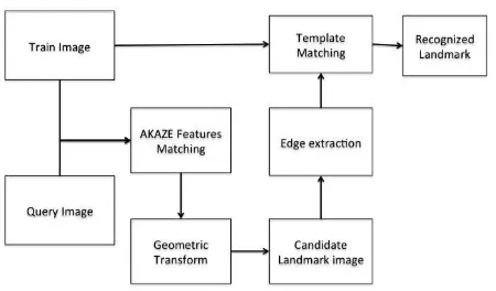
Figure 2. Proposed landmark recognition scheme
same size as the train image. If it were a true positive recog-nition, both images would be the same and a false positive en-counter would produce a different image. In order to evaluate it, a template matching method was used. So the edges of both the candidate and the train image were extracted, resulting in two bi-nary images. Those images would be used to compute the classic correlation coefficient using equation 1, where T is the train edge image and I is the candidate edge image. In case the correlation coefficient is higher than a threshold, the landmark is finally rec-ognized. Figure 2 show each step for recognition.
R(x, y) =
From the recognized landmark, it is possible to extract the latitude and longitude information for the autonomous navigation system. This position information derivates from the general affine trans-form obtained in the recognition process. It is generated by the matched keypoints. ConsideringF : T(x, y) 7→ G(lat, long)
the Geo-referencing relation from the pattern image T with the Object Space G, andK : T(x, y) 7→ Q(X, Y)the Geometric
Transformation that maps the pattern image T in the query image Q, it is possible to build the Geo-referencing transformationH, from the query image Q, in which:
H:Q(X, Y)−K−−−→1 T(x, y)−F→G(lat, long) (2)
It is not necessary for the pattern image to be fully geo-referenced, to do the image-to-image Geo-referencing process of the query image using the landmark recognition. If there are at least three points in the pattern image data with the associated latitude and longitude information, it is possible to perform the geo-referencing. In extreme case, if only one point in the pat-tern image had the latitude and longitude information, it would be possible to register the image if at least three landmarks would be recognized in the same frame.
Choosing the points that will have Latitude and Longitude infor-mation in the pattern image is an important aspect, since they are responsible for the system of linear equations for the image geo-referencing, and the system must be a possible and determined one. Those points will be the ground control points (GCP) for the process.
In terms of the Image geo-referencing, though, it is necessary to take into consideration the spatial resolution of the image when choosing the control points. The limitation on decimal represen-tation in computers determines a minimum real distance that the points must have, in order not to affect the system of equations making it an impossible one. Moreover, the floating point preci-sion must be taken into consideration when choosing each GCP.
The affine geometric transformation obtained is now used to find the corresponding points in the query image of each GCP of the pattern image. The points obtained are then used to obtain the image-to-image geo-referencing affine function, which will esti-mate the UAV position. We consider the center pixel of the query image as the point that maps the perspective center, since the im-ages are taken in the nadir view, so that its estimated latitude and longitude is the also considered the UAVs position.
3. EXPERIMENTS AND RESULTS
The experiments developed intended to validate the proposed method to estimate the position of an UAV during flight for a vision based navigation system. The tests performed focused on identifying position and on how accurate those positions were, compared with a previously known data.
There were two main tracks of experiments developed: Geo-referencing a Satellite Video frame and Auto-localization of a UAV. These different tests were built because of an initial lack of proper data to compare the results and validate the method. It is not easily found datasets of aerial images with corresponding flight data in the literature to compare results and in order to test the method and analyze the results this particular data was first produced using academic small quadcopter.
The experiments were performed in a MAC OSX 10.10 with a 2.6GHz Intel Core i7, 8GB 1600MHz DDR3 RAM and NVIDIA GeForce GT 650M 1024 MB, which could be used as a ground station for the UAV.
3.1 Geo-referencing a Satellite Video Frame
The first experiment was performed using a dataset provided by the IGRSS 2016 Data fusion Contest (DEIMOS, 2016). It con-sists of a Panchromatic data at 1m spatial resolution that was ob-tained from the DEIMOS-2 Satellite (CCD sensor) and a high definition video, with 1032 frames, and resolution of 3840x2160 pixels, acquired from the International Space Station at also 1m spatial resolution (CMOS sensor).
This test intended to observe three aspects. The first aspect was the use of satellite images, as they are a possible source of train images for landmarks. The second was related with the recog-nition in images provided by different sensors. Different sensors can capture different visual information and pose as a challenge for the recognition. The third and mas aspect was how the indi-rect image-to-image geo-referencing method would work.
Table 1. Indirect geo-referencing of the video frame, from landmark recognition.
Video Pos. Image Pos. Error (m) (1711;600) (1762;5057) 7.1 (2185;712) (1957;4678) 6.6 (1675;1172) (2219;5204) 16.5 (1172;1912) (2714;5783) 25.8 (2841;1103) (2426;4219) 3.9
(2751;464) (1882;4151) 6.7 (1551;1033) (2084;5273) 9.2 (335;1221) (1953;6323) 33.7
(98;1732) (2320;6633) 38.9 (2203;299) (1622;4572) 4.0
Figure 3. Result for the indirect Geo-referencing of a frame. The green dots are the real position and the red dots are the estimated
position.
This selected landmark had latitude and longitude information in each pixels of the train image. From the recognition of the landmark, each frame of the video was then geo-referenced, using the method described in section 2.2.
Ten points from the video frame were randomly chosen in every part of the frame and used to evaluate the indirect geo-referencing method. It was decided to used ten points in order to evaluate how the error was distributed throughout the image. Their results on the indirect geo-referenced frame were compared with the cor-responding points in the satellite geo-referenced image that pro-vided the train image. Table 1 shows the results for these ten points.
The average error obtained is similar to the GPS error and the er-ror that is usually obtained in image registration software, such as ENVI. Points with higher error are the ones that are more distant form the recognized landmark. A better registration would prob-ably be obtained if more than one landmark were selected to be recognized in the frame. Figure 3 shows the result on the video frame.
3.2 UAV Auto-localization
The second experiment developed was closer to how would an aircraft recognize the landmark and estimate its position during flight. The dataset used for this experiment was a sequence of aerial images obtained from a Rotary-wing UAV (a quadcopter). The flight was performed in the 07/31/2015, at 16:30, average
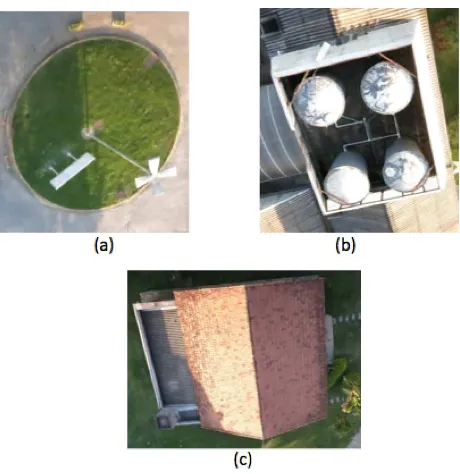
Figure 4. Landmarks chosen from the pattern image flight (07/31/2015). (a) is a roundabout landmark, (b) is the roof of the
engineering building, and (c) is the roof of a house
flight height of 30m and average speed of 3m/s. The aerial im-ages were taken with Nadir view, and at a frequency of 3 photos per second, with a pixel resolution of 4000x3000. It was also pos-sible to obtain the flight logs, with information from the IMU and the GPS embedded in the aircraft, synchronized with each image from the sequences. The landmarks chosen were as in Figure 4, and they were obtained in the same aerial images. Four control points were randomly selected in each landmark, using a 2011 geo-referenced image of the area. These points are the GCP for the image registration, which is used for the position estimation.
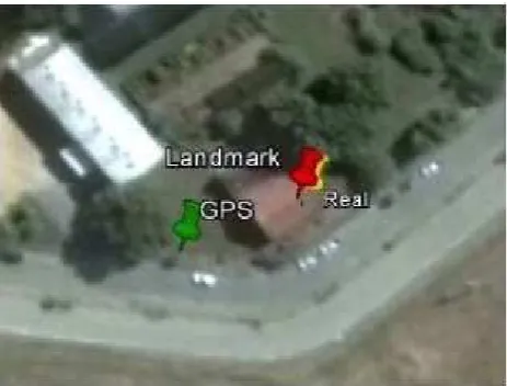
The algorithm then was performed in the sequence of images. As the landmarks were recognized, the position was estimated and compared with the corresponding GPS data for each image in which the landmark was recognized. Table 2 shows the error in meters of the comparison between the estimated position and the position obtained by the onboard GPS. Figures 5, 6, and 7 illustrate the positions plotted on a map, and compared with the position of the center of each image were the landmark was rec-ognized.
Table 2. Autolocalization error compared with the UAV GPS
Landmark Error (m)
19.8
20.5
24.4
Figure 5. Auto-localization position comparison between GPS, Landmark Recognition Estimation, Real UAV Position in the
roundabout landmark.
Figure 6. Auto-localization position comparison between GPS, Landmark Recognition Estimation, Real UAV Position in the
house landmark.
camera could capture a scene as the corresponding image is. In a more quantitative way, from the 2011 image of the area of flight, it was possible to geo-reference the UAV image using ENVI and estimate the central pixel latitude and longitude, which was con-sidered as the UAV real position for comparison. From these re-sults, it can be assumed that the method developed is a suitable alternative or redundant position estimator, to be used in a visual navigation system.
4. CONCLUSION
Landmark recognition-based autonomous navigation systems, then, proved to be a valid and promising strategy to be applied and further explored for a UAV visual navigation system. There are few works in this area and most of them are in a more heuris-tic approach, or use artificial landmarks. There are still exper-iments and adaptations to be developed in the recognition area, such as flight using other sensors and other environments. The auto-localization results although, were quite satisfactory, as they were more accurate than the GPS data available.
As Future works, an in-flight experiment is going to be
per-Figure 7. Auto-localization position comparison between GPS, Landmark Recognition Estimation, Real UAV Position in the
rooftop landmark.
formed, in order to better evaluate the position estimated during flight. At first, the UAV will send its captured image to a ground station, which will process the image and obtain the position in-formation (Latitude and Longitude) as soon as the landmark is recognized. The results will be compared with a usual GPS and a Referential GPS (RTK). Then, the algorithm will be adapted in order to be embedded in the aircraft.
5. ACKNOWLEDGEMENT
This research is part of a project funded by the Brazilian Air-Force. The Authors would like to thank FUNCATE and their Geoprocessing project for providing the means to participate in the conference.
REFERENCES
Alcantarilla, P. F., Nuevo, J. and Bartoli, A., 2011. Fast explicit diffusion for accelerated features in nonlinear scale spaces.IEEE Trans. Patt. Anal. Mach. Intell34(7), pp. 1281–1298.
Azizi, A., Nourisola, H. and Ghiasi, A. R., 2016. 3d inertial al-gorithm of slam for using on uav. In:Robotics and Mechatronics (ICROM), 2016 4th International Conference on, IEEE, pp. 122– 129.
Blumenau, A., Ishak, A., Limone, B., Mintz, Z., Russell, C., Su-dol, A., Linton, R., Lai, L., Padir, T. and Van Hook, R., 2013. De-sign and implementation of an intelligent portable aerial surveil-lance system (ipass). Technologies for Practical Robot Applica-tions (TePRA)pp. 1–6.
Braga, J. R., Velho, H. d. C. and Shiguemori, H., 2015. Estima-tion of uav posiEstima-tion using lidar images for autonomous navigaEstima-tion over the ocean. In:2015 9th International Conference on Sensing Technology (ICST), IEEE, pp. 811–816.
Cruz, J. E. C., 2014. Reconhecimento de objetos em imagens orbitais com o uso de abordagens do tipo descritor-classificador. Master’s thesis, INPE.
DEIMOS, 2016. 2016 ieee grss data fusion contest. Online: http://www.grss-ieee.org/community/technical-committees/data-fusion.
Dumble, S. and Gibbens, P., 2014. Efficient terrain-aided visual horizon based attitude estimation and localization. Journal of Inteligent and Robotic Systems.
Farag, A. A. and Abdel-Hakim, A. E., 2004. Detection, catego-rization and recognition of road signs for autonomous navigation. In:Proceedings of ACIVS, pp. 125–130.
Kezheng, L., Huanzhou, M. and Lang, W., 2015. Recognition algorithm of landmark for quadrotors aircraft based on image feature of corner points. In: Information and Automation, 2015 IEEE International Conference on, IEEE, pp. 1437–1440.
Lee, J.-O., Kang, T., Lee, K.-H., Im, S. K. and Park, J., 2010. Vision-based indoor localization for unmanned aerial vehicles.
Journal of Aerospace Engineering24(3), pp. 373–377.
LeMieux, J., 2012. Alternative uav navigation systems.
Li, Y., Wang, S., Tian, Q. and Ding, X., 2015. A survey of re-cent advances in visual feature detection. Neurocomputing149, pp. 736–751.
Lowe, D. G., 2004. Distinctive image features from scale-invariant keypoints. International journal of computer vision
60(2), pp. 91–110.
Michaelsen, E. and Meidow, J., 2014. Stochastic reasoning for structural pattern recognition: An example from image-based uav navigation.Pattern Recognition47(8), pp. 2732–2744.
Muella, M. T. d. A. H., 2008. Morfologia e Dinˆamica das Ir-regularidades de Pequena Escala e Imageamento Ionosf´erico por GPS. PhD thesis, INPE.
Pajares, G., 2015. Overview and current status of remote sens-ing applications based on unmanned aerial vehicles (uavs). Pho-togrammetric Engineering & Remote Sensing 81(4), pp. 281– 329.
Quist, E. B. and Beard, R. W., 2016. Radar odometry on fixed-wing small unmanned aircraft.IEEE Transactions on Aerospace and Electronic Systems52(1), pp. 396–410.
Rady, S., Kandil, A. and Badreddin, E., 2011. A hybrid local-ization approach for UAV in GPS denied areas. International Symposium on System Integration (SII)pp. 1269–1274.
Rublee, E., Garage, W., Park, M., Rabaud, V., Konolige, K. and Bradski, G., 2011. Orb: An efficient alternative to sift or surf.
International Conference on Computer Vision (ICCV)pp. 2564 – 2571.
Silva, C. A. O., 2015. Avaliac¸˜ao da t´ecnica de casamento de im-agens aplicada `a localizac¸˜ao geogr´afica de vants. Master’s thesis, UFMG.
Silva Filho, P. F. F., 2016. Automatic landmark recognition in aerial images for the autonomous navigation system of un-manned aerial vehicles. Master’s thesis, Instituto Tecnol´ogico de Aeron´autica (ITA), S˜ao Jos´e dos Campos-SP.
Silva Filho, P., Rodrigues, M., Saotome, O. and Shiguemori, E. H., 2014. Fuzzy-based automatic landmark recognition in aerial images using orb for aerial auto-localization. In:Advances in Visual Computing, Springer, pp. 467–476.
Singh, S. and Sujit, P., 2016. Landmarks based path planning for uavs in gps-denied areas this work is partially funded by fct grant sfrh/bpd/103962/2014.IFAC-PapersOnLine49(1), pp. 396–400.
Takahashi, H., Wrasse, C., Denardini, C., Costa, S., Ivo, A., Sant’Anna, N., Otsuka, Y. and Shiokawa, K., 2015. Large scale plasma bubbles observed by gps tec mapping over south amer-ica. In:14th International Congress of the Brazilian Geophysical Society & EXPOGEF, Rio de Janeiro, Brazil, 3-6 August 2015, Brazilian Geophysical Society, pp. 1437–1438.
Zhao, X., Fei, Q. and Geng, Q., 2013. Vision based ground target tracking for rotor uav. Control and Automation (ICCA)pp. 1907 – 1911.