Digitally-Assisted Stone Carving of a Relief Sculpture for the Parliament
Buildings National Historic Site of Canada
James Hayes
a, Stephen Fai
a, Shawn Kretz
b, Christian Ouimet
b, Phil White
ba
Carleton Immersive Media Studio, Carleton University,VSIM Building 1125 Colonel By Drive, Ottawa, Canada - (jhayes, sfai)@cims.carleton.ca,
b
Public Works and Government Services Canada, 30 Victoria Street, Gatineau, Canada - (shawn.kretz, christian.ouimet, phil.white)@tpsgc-pwgsc.gc.ca,
KEY WORDS: Digital fabrication, Photogrammetry, Laser Scanning, Stone Carving, Point Cloud, Polygon Mesh
ABSTRACT:
The emerging field of digital fabrication is a process where three-dimensional datasets can be directly transferred to fabrication equipment to create models or even 1:1 building elements. In this paper, we will discuss the results of a collaboration between the Carleton Immersive Media Studio (CIMS), the Dominion Sculptor of Canada, and the Heritage Conservation Directorate (HCD) of Public Works and Government Services Canada (PWGSC), that utilizes digital fabrication technologies in the development of a digitally-assisted stone carving process.
The collaboration couples the distinguished skill of the Dominion Sculptor with the latest digital acquisition and digital fabrication technologies for the reconstruction of a deteriorated stone bas-relief on the façade of the East Block building of the Parliament Buildings National Historic Site of Canada. The intention of the research is to establish a workflow of hybrid digital/analogue methodologies from acquisition through rehabilitation and ultimately to the fabrication of stone elements.
1. INTRODUCTION
Digital acquisition technologies such as laser scanning and photogrammetry have become integral to heritage documentation. Coupling the acquisition technology with digital fabrication technology can potentially expand the contributions of heritage documentation in the preservation of heritage assets. The monitoring of heritage assets (Salonia et al., 2011), the creation of 2-D line drawings (Angelini et al., 2011), online interactive models (Abate et al., 2011) and the creation of BIM models (Fai et al., 2013), is a non-exhaustive list illustrating the broad spectrum of uses for digital acquisition datasets. However, using the datasets from heritage recording for digital fabrication has had significantly less study. The fabrication of replicas for museums (Allard et al., 2005), (Cooper et al., 2006), and archaeological study (Fatuzzo et al., 2011), has been documented but the fabrication of substantive building materials as part of heritage conservation work is a nascent field.
1.2 Background
The Parliament Buildings National Historic Site of Canada is comprised of four monumental buildings — the Library of Parliament and the West, Centre and East Blocks. The Library of Parliament underwent an extensive rehabilitation between 2002 and 2006. The West Block rehabilitation began in 2011 and the Centre Block, and East Block will each undergo significant conservation and rehabilitation work successively.
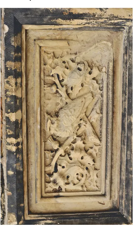
The East Block was original constructed in 1865. As the young country of Canada continued to expand, a new wing was added in 1910 to the original ‘L’ shaped building creating a courtyard. Above the entrance to the courtyard a 1725mm x 1120mm rectangular Berea sandstone relief sculpture of an owl perched among thistles was set into the façade.
Unfortunately, the owl and thistle relief sculpture was carved with the bedding plane of the sandstone oriented vertically or face-bedded. As is well documented, sandstone used in building should be laid so that the bedding plane is oriented horizontally, or naturally-bedded (Grimmer, 1984). As a result of the incorrect orientation, the sculpture has deteriorated significantly since it was carved in 1910. The lower right corner and much of the detail of the owl is missing, having delaminated from the rest of the sandstone and fallen off (fig. 1).
As part of ongoing conservation work by Public Works and Government Services Canada (PWGSC), the relief sculpture was identified to be replaced. The replacement of the sculpture was seen as an opportunity to research the development of a workflow for digitally-assisted stone carving. The project is a collaboration between the Dominion Sculptor, who is responsible for creating significant architectural stone, wood, and bronze sculptures on Parliament Hill, the Heritage Conservation Directorate (HCD) of PWGSC, and the Carleton Immersive Media Studio of Carleton University. The following was proposed as the workflow for the replacement process:
ISPRS Annals of the Photogrammetry, Remote Sensing and Spatial Information Sciences, Volume II-5/W3, 2015 25th International CIPA Symposium 2015, 31 August – 04 September 2015, Taipei, Taiwan
• Digital acquisition of the sculpture by HCD.
• Post processing of the digital dataset by CIMS
• Digital fabrication of a 1:1 foam maquette by CIMS
• Clay repairs overlaid on the maquette by the Dominion Sculptor
• Digital acquisition of the maquette with clay repairs by HCD
• Post processing of the digital dataset by CIMS
• Digital fabrication in sandstone of the sculpture by CIMS
• Hand finish of the sculpture by the Dominion Sculptor
Figure 1. Owl and thistle sandstone relief sculpture
2. PRELIMINARY RESEARCH
2.1 Proof-of-Concept
Prior to the work on the owl and thistle sculpture, three proof-of-concept projects were completed to investigate how digital
acquisition and digital fabrication might assist in the repair of damaged sculptural stone elements scheduled for repair on the West Block. Two different digital acquisition technologies as well as two different digital fabrication technologies were tested in the acquisition and fabrication of a gargoyle, pilaster capital, and tympanum.
2.2 Digital Acquisition
The gargoyle and tympanum were digitized using photographs taken using a digital SLR and the photogrammetric software
Photoscan by Agisoft. Traditional film based photogrammetry was utilized heavily at HCD before digital photogrammetry became a viable source for the derivation of accurate metric information. Over time the process has moved from mechanical devices to software that extracts measurements and allows real-time drawing in 3D in AutoCAD.
Photoscan is a relatively new software used in the workflow of the Heritage Conservation Directorate (HCD). The distinct difference between Photoscan and earlier software such as
Shape Capture and Imagemaster is the level of automation in the matching of common points found in the images and the automation of camera calibration. This allows users other than a specialized photogrammetrist to produce relatively accurate 3D models from images taken using specific photogrammetric techniques.
A pilaster capital was chosen as the subject to test the second digital acquisition technology – a hand-held scanner. The
Creaform Handyscan 3D is a hand-held scanning device that uses triangulation of the laser cross hairs it projects onto the object, the position of the laser emitter, and two cameras. The two main cameras are surrounded by halos of white LEDs to light the object being scanned while a third camera captures the colour of the object. The system requires proprietary
VXelements software installed on a notebook computer connected to the scanner while the scanner is in use. Positioning is accomplished using reflective sticker dots placed on the object in a distribution of 5-7 inches apart from one another. By capturing the unique constellation of positioning points, the software is able to generate the scanned information of the 3D mesh in real-time on the screen of the notebook computer. One advantage to this type of scanning technology is the user can be confident that the dataset is complete because they can see the results of the scan during the process of documentation. Additionally, the polygon mesh generated by the scanner is “clean” requiring minimal post processing work to optimize the polygon mesh for fabrication.
2.3 Data for Fabrication
In order for the datasets produced by laser scanning or photogrammetry to be useful for digital fabrication certain processes are required to prepare the datasets using point-cloud and mesh processing software such as Geomagic Studio or
the Handyscan 3D produce polygon mesh models directly without the added step of converting point-clouds to meshes. Additionally, polygon meshes must have certain characteristics in order to be used for fabrication. The most important characteristic being what is referred to as “water‐tightness” (Liu et al.,2007). A water-tight mesh is a polygon mesh with no openings, from obvious holes caused by occlusion to less obvious naked edges or non‐manifold faces. Further technical requirements include ensuring the mesh does not have self-intersecting faces or small tunnels and ensuring the mesh has unified normal. Closing holes in a polygon mesh haphazardly will also result ininaccurate results. A dataset with large areas of occlusion and high levels of noise makes preparation for fabrication difficult if not impossible.
Satisfying the technical requirements outlined above will produce a polygon mesh that is suitable for fabrication. However, the success of the fabrication – whether the fabricated object is an accurate reproduction of the original – is also influenced by “noise” in the mesh and the craft in making the mesh watertight. A noisy polygon mesh can create undesirable surface artifacts on the digitally fabricated object that do not reflect the geometry of the surface of the original object. (Fig 2.) In the context of stone masonry conservation it is important that surface detail such as original tooling marks or erosion patterns not be obscured by artifacts from the polygon mesh.
In the three proof-of-concept projects, it was our observation that there were significantly less technical problems with the polygon mesh created by the hand-held scanner than the polygon mesh created using the photogrammetric software. The overall geometry of the polygon meshes created by the two different techniques was equivalent. However, when preparing the polygon meshes for fabrication, more time was required for the polygon meshes created by the photogrammetric software than the polygon meshes created by the hand-held scanner.
Figure 2. Surface artifacts on CNC-milled maquette as a result of poor mesh quality
2.4 Digital Fabrication
CIMS has direct use of a Dimension SST 1200es 3D printer (additive fabrication), as wells as a 3-axis AXYZ CNC router (subtractive fabrication). In the context of the AEC industry, digital fabrication technologies can be placed in two general
categories, additive fabrication and subtractive fabrication (Kolarevic, 2001). Additive fabrication works by adding successive layers of material over time, until an object has been created. 3D printers are an example of additive fabrication. Subtractive fabrication, on the contrary, begins with a piece of material and an object is formed by removing, or subtracting, material from the piece with a cutting tool. CNC routers, waterjets and milling robots are examples of subtractive fabrication.
Figure 3. Pilaster capital (top) and 1:1 3D-printed capital maquette (bottom)
The advantages of additive manufacturing are the ability to produce objects of great geometrical complexity coupled with the relative ease of use of the technology. For this reason, the complex forms of the gargoyle and capital were chosen to be fabricated using the 3D printer. The printer which uses fused deposition modelling technology extrudes ABS plastic in successive 0.254 mm layers over and over until the object is formed. The main disadvantage of additive fabrication in the context of the AEC industry is the limited size of objects that can be produced. With the exception of price-prohibitive or experimental technologies, additive fabrication is generally restricted to creating small objects that fit within a 254mm x 254mm x 310mm build area. Both the gargoyle and the capital were too large to print at a scale of 1:1 in a single print. The gargoyle maquette was therefore printed at a scale of 1:10 and the capital maquette was printed as four separate pieces and assembled after printing at full scale (fig. 3). The size limitation and the synthetic materials of objects created using additive technologies mean they are typically more suitable for maquettes and prototypes, as opposed to objects that actually become part of a building.
ISPRS Annals of the Photogrammetry, Remote Sensing and Spatial Information Sciences, Volume II-5/W3, 2015 25th International CIPA Symposium 2015, 31 August – 04 September 2015, Taipei, Taiwan
The tympanum was the largest of the three elements – measuring over a meter wide – and was therefore more suited to subtractive fabrication. The main advantage of subtractive manufacturing is that objects can be fabricated at a scale that is typical of building components and they can be cut or milled from familiar building materials such as wood and steel. The maquette of the tympanum was milled from medium-density fibre board (MDF) at a scale of 1:1 on a 3-axis AXYZ CNC router (fig. 4). The main disadvantage of subtractive fabrication is that it can be difficult to use, typically taking the form of industrial machinery operated by skilled technicians. This can make subtractive fabrication inaccessible to someone not familiar with such technology.
Figure 4. Polygon mesh model of tympanum (top) and CNC milled tympanum maquette (bottom)
3. DIGITALLY-ASSISTED STONE CARVING
3.1 Capturing the Owl – Digital Acquisition of the Relief Sculpture
The owl and thistle relief sculpture on the East Block was documented primarily by photogrammetry. A boom lift was used to perform the work because of the location of the sculpture above an arched porte-cochere. The sculpture was photographed using a Nikon D3x DSLR. Portions of the sculpture were also scanned using the Handyscan 3D hand-held scanner. Unfortunately, inclement weather conditions made a comprehensive scan impossible, leaving an incomplete dataset. The photogrammetric images were used to produce a mesh of the sculpture – following the process described above (fig 5). Data from the scanner was used to provide scale.
Figure 5. Polygon mesh model created using Agisoft Photoscan
3.2 Digitally-Assisted Fabrication of the Maquette
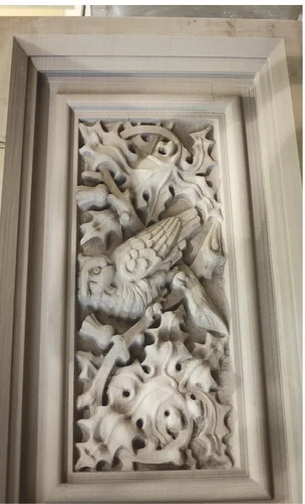
The polygon mesh was exported from Photoscan and repaired and optimized using Geomagic Studio in preparation for fabrication. Based on the three proof-of-concept projects and the size of the owl and thistle sculpture, the only feasible technology for fabricating the maquette was the 3-axis CNC router. Using the data from the photogrammetric model, the maquette was milled from 10lbs/ft2 density polyurethane foam at a scale of 1:1. The maquette then served as a foundation for the work of the Dominion Sculptor. In the areas where the sandstone had eroded or delaminated and fallen off, the Dominion Sculptor crafted an overlay of modelling clay to those areas on the maquette (fig. 6,7).
Figure 7. CNC-milled polyurethane foam maquette of relief sculpture with modelling clay applied
3.3 Digital Acquisition of the Maquette with Clay Repairs
Themaquette, with the clay repairs applied, was digitized using the Handyscan 3D (fig. 8). Again, the work to prepare this polygon mesh for fabrication was significantly less than the work required to prepare the polygon mesh from the Photoscan
data used for the foam maquette. This is evidenced by comparing the data created by Photoscan of the sandstone sculpture to the data of the maquette using the Handyscan 3D in the software Geomagic Studio.
The polygon mesh created by Photoscan had 443,264 self-intersecting faces out of a total 49,568,604 faces; while the polygon mesh from the Handyscan 3D had 6 self-intersecting faces out of a total of 5,953,650 faces. Adjusting for the disparity in the total number of faces, proportionally the
Photoscan mesh had the equivalent of 53,240 self-intersecting faces. Further the Photoscan mesh had 2599 small tunnels and the Handyscan mesh had 0 small tunnels. The removal of such undesirable conditions as self-intersecting faces and small tunnels is paramount for successful fabrication.
Figure 8. Polygon mesh model of the maquette created using a
Creaform Handyscan 3D
3.4 Robotic Milling of Sandstone
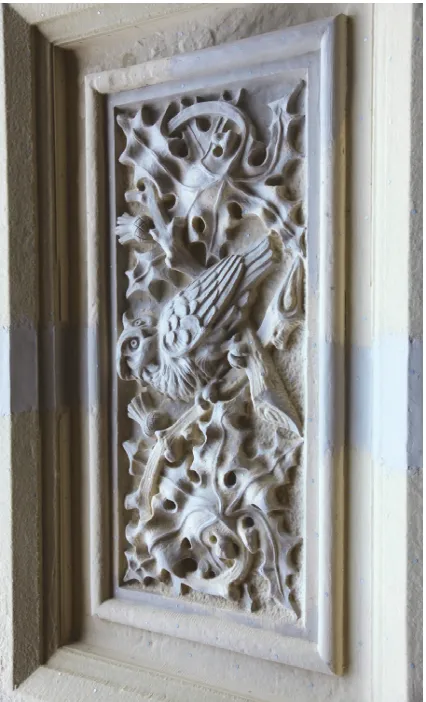
The final dataset from the maquette was used to fabricate the owl and thistle relief sculpture from a 2200 kg block of sandstone. This was accomplished – in association with New Age Robotics – using a 6-axis Kuka robot equipped with a 20hp spindle powering electroplated diamond stone-milling tools. The sandstone was milled by the robot to within 2mm of the proposed final surface (fig. 9). The 2mm of material left by the robot will be removed by the Dominion Sculptor when he applies a traditional finish to the sculpture.
3.5 Hand Finishing
The tool marks on the original sculpture were analysed by the Dominion Sculptor in order to determine the tools and techniques used to create the original sculpture. These same tools and techniques – a hand-held mallet used in combination with punches, toothed chisels, and flat chisels – are being employed to apply the final details and finishes to the replacement sculpture.
Punches and chisels that come to a fine point, are used first to quickly rough out the forms. The use of punches creates a relatively rough surface, characterized by pockmarks where the narrow point of the chisel impacts the stone surface. The rough surface left by the punch can be further refined with wider chisels or left rough where it is desired to catch light and create shadow. In the case of the original sculpture, the background and undercutting were not further refined, instead it was left with a rough, but clearly defined surface.
ISPRS Annals of the Photogrammetry, Remote Sensing and Spatial Information Sciences, Volume II-5/W3, 2015 25th International CIPA Symposium 2015, 31 August – 04 September 2015, Taipei, Taiwan
Figure 9. Robotically milled sandstone relief sculpture, prior to hand-applied finish
A toothed chisel generally follows the use of punches. The toothed chisel smooths out the rough surfaces left by the pointed punch, but leaves a series of parallel lines. These lines are often left on the surface of the stone to create particular textures and shadows. Many of the surfaces on the original sculpture were left with the finish of the toothed chisel, which is particularly noticeable on the undulating leaves, and along the length of the stems, creating contrast with the surfaces of the background.
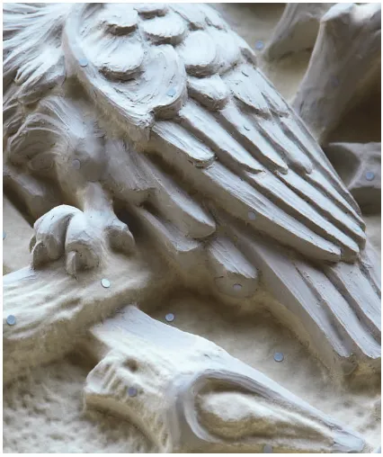
A flat chisel, which has a smooth straight edge, is used to refine the stone surface, removing the finish left by the toothed chisel and to add definition. This can be seen on the fine veining of the leaves, and the definition of the feathers on the owl. Figure 10 shows the progress of the hand finishing.
4. CONLCUSIONS
The owl and thistle relief sculpture project demonstrates that the datasets generated by digital acquisition technologies when paired with digital fabrication technologies can expand the contributions of heritage documentation for preservation and rehabilitation work. Whether the fabrication takes the form of a
maquette or an actual building component, the ability to supplement digital datasets with a physical counterpart is a powerful tool. All of the maquettes fabricated for the proof of concept project and the owl and thistle project recorded fine detail of the sculptures including the tool marks from the original stone carver’s tools. As a result of this study, HCD has been given the mandate to document all of the sculptural elements on the West Block – using a combination of the hand-held scanner and photogrammetry – in order to create a record of both the architectural ornament and the carving techniques used in their production.
Figure 10. Hand-applied finish on the left and robotic-milled finish on the right
REFERENCES
Abate, D., Furini, G., Migliori S., Pierattini S., 2011. Multiple Visualization Web Approach for Cultural Heritage Objects.
XXIII CIPA Symposium, Prague, Czech Republic.
Allard, T., Sitchon, M., Sawatzky, R., Hoppa R., 2005. Use of Hand-Held Laser Scanning and 3D Printing for Creation of a Museum Exhibit, Proceedings of 6th International Symposium on Virtual Reality, Archaeology and Cultural Heritage VAST 2005, Pisa, Italy.
Angelini, M.G., Costantino, D., Milano, N., 2011. 3D and 2D Documentation and Visualization of Architectural Historic Heritage. XXIII CIPA Symposium, Prague, Czech Republic.
Cignoni, P., Callieri, M., Corsini, M., Dellepiane M., Ganovelli, F., Ranzuglia. G., 2008. MeshLab: an Open-Source Mesh Processing Tool. Eurographics Italian Chapter Conference. pp. 129-136.
Cooper, M., La Pensée, A., Parsons, J., 2006. The Use of Laser Scanning and Rapid Manufacturing Techniques for Museum Exhibitions. Proceedings of 7th International Symposium on Virtual Reality, Archaeology and Cultural Heritage, Nicosia, Cyprus.
Fai, S., Filippi, M., Paliaga, S., 2013. Parametric Modelling (BIM) for the Documentation of Vernacular Construction Methods: A BIM Model for the Commissariat Building, Ottawa, Canada. XXIV International CIPA Symposium, Strasbourg, France.
Fatuzzo, G., Mussumeci, G., Oliveri, S.M. and Sequenzia, G., 2011, 'The “Guerriero di Castiglione”: Reconstructing Missing Elements with Integrated Non-destructive 3D modelling techniques', Journal of Archaeological Science, 38, pp. 3533-3540.
Grimmer, A.E., 1984, A Glossary of Historic Masonry Deterioration Problems and Preservation Treatments, Department of the Interior National Park Service Preservation Assistance Division, Washington, DC.
Kolarevic, B., 2001. Digital Fabrication: Manufacturing Architecture in the Information Age, Proceedings of the Twenty First Annual Conference of the Association for Computer-Aided Design in Architecture, Buffalo, New York. pp. 268-278.
Liu, R., Burschka, D., Hirzinger, G., 2007. On the Way to Water-tight Mesh, ISPRS 3D-ARCH 07, Zurich, Switzerland.
Salonia, P., Leti, M., Marcolongo, A., Appolonia, L., 2011. Photo Scanner 3D Survey for Monitoring Historical Monuments: The Case History of Porta Praetoria in Aosta.
XXIII International CIPA Symposium, Prague, Czech Republic.
ISPRS Annals of the Photogrammetry, Remote Sensing and Spatial Information Sciences, Volume II-5/W3, 2015 25th International CIPA Symposium 2015, 31 August – 04 September 2015, Taipei, Taiwan