POWER
POWER
ELECTRONICS
HANDBOOK
DEVICES, CIRCUITS, AND APPLICATIONS
Third Edition
Edited by
Muhammad H. Rashid, Ph.D.,
Fellow IET (UK), Fellow IEEE (USA)
Professor
Electrical and Computer Engineering
University of West Florida
11000 University Parkway
Pensacola, FL 32514-5754, U.S.A.
Phone: 850-474-2976
e-mail: [email protected]
AMSTERDAM • BOSTON • HEIDELBERG • LONDON • NEW YORK • OXFORD PARIS • SAN DIEGO • SAN FRANCISCO • SINGAPORE • SYDNEY • TOKYO
30 Corporate Drive, Suite 400, Burlington, MA 01803, USA Linacre House, Jordan Hill, Oxford OX2 8DP, UK
Second edition 2007 Third edition 2011
Copyright c2011, Elsevier Inc. All rights reserved.
No part of this publication may be reproduced, stored in a retrieval system, or transmitted in any form or by any means, electronic, mechanical, photocopying, recording, or otherwise, without the prior written permission of the publisher.
Permissions may be sought directly from Elsevier’s Science & Technology Rights Department in Oxford, UK: phone: (+44) 1865 843830, fax: (+44) 1865 853333, E-mail: [email protected]. You may also complete your request online via the Elsevier homepage (http://elsevier.com), by selecting “Support & Contact” then “Copyright and Permission” and then “Obtaining Permissions.”
Library of Congress Cataloging-in-Publication Data
Power electronics handbook : devices, circuits, and applications handbook / edited by Muhammad H. Rashid. – 3rd ed.
p. cm.
ISBN 978-0-12-382036-5
1. Power electronics – Encyclopedias. I. Rashid, M. H. TK7881.15.P6733 2010
621.31'7–dc22
2010038332
British Library Cataloguing-in-Publication Data
A catalogue record for this book is available from the British Library.
ISBN: 978-0-12-382036-5
For information on all Butterworth-Heinemann publications visit our Web site atwww.elsevierdirect.com
Printed in the USA
Dedication
To those who promote power electronics and inspire students for finding applications for the benefits of the people and the environment in the global community
Table of Contents
Chapter 1 Introduction
Philip T. Krein
Department of Electrical and Computer Engineering University of Illinois
Urbana, Illinois, USA
1
Section I: Power Electronics Devices
Chapter 2 The Power Diode
Ali I. Maswood School of EEE
Nanyang Technological University Nanyang Avenue, Singapore
17
Chapter 3 Power Bipolar Transistors
Marcelo Godoy Simoes Engineering Division Colorado School of Mines Golden, Colorado, USA
29
Chapter 4 The Power MOSFET
Issa Batarseh
School of Electrical Engineering and Computer Science University of Central Florida
4000 Central Florida Blvd. Orlando, Florida, USA
43
Chapter 5 Insulated Gate Bipolar Transistor
S. Abedinpour and K. Shenai
Department of Electrical Engineering and Computer Science University of Illinois at Chicago
851, South Morgan Street (M/C 154) Chicago, Illinois, USA
73
Chapter 6 Thyristors
Angus Bryant
Department of Engineering University of Warwick Coventry CV4 7AL, UK
Enrico Santi
Department of Electrical Engineering University of South Carolina Columbia, South Carolina, USA
Jerry Hudgins
Department of Electrical Engineering University of Nebraska
Lincoln, Nebraska, USA
Patrick Palmer
Department of Engineering University of Cambridge Trumpington Street Cambridge CB2 1PZ, UK
91
Chapter 7 Gate Turn-off Thyristors
Muhammad H. Rashid
Electrical and Computer Engineering University of West Florida
11000 University Parkway
Pensacola, Florida 32514-5754, USA
117
Chapter 8 MOS Controlled Thyristors (MCTs)
S. Yuvarajan
Department of Electrical Engineering North Dakota State University P.O. Box 5285
Fargo, North Dakota, USA
125
Chapter 9 Static Induction Devices
Bogdan M. Wilamowski
Alabama Microelectronics Science and Technology Center Auburn University
Alabama, USA
135
Section II: Power Conversion
Chapter 10 Diode Rectifiers
Yim-Shu Lee and Martin H. L. Chow
Department of Electronic and Information Engineering The Hong Kong Polytechnic
University Hung Hom Hong Kong
Chapter 11 Single-phase Controlled Rectifiers
Jos´e Rodr´ıguez, Pablo Lezana,
Samir Kouro, and Alejandro Weinstein Department of Electronics
Universidad T´ecnica Federico Santa Mar´ıa, Valpara´ıso, Chile
183
Chapter 12 Three-phase Controlled Rectifiers
Juan W. Dixon
Department of Electrical Engineering Pontificia Universidad Cat´olica de Chile Vicu˜na Mackenna 4860, Santiago, Chile
205
Chapter 13 DC–DC Converters
Dariusz Czarkowski
Department of Electrical and Computer Engineering Polytechnic University
Brooklyn, New York, USA
249
Chapter 14 DC/DC Conversion Technique and Twelve Series Luo-converters
Fang Lin Luo
School of EEE, Block S1
Nanyang Technological University Nanyang Avenue, Singapore Hong Ye
School of Biological Sciences, Block SBS Nanyang Technological University Nanyang Avenue, Singapore
265
Chapter 15 Inverters
Jos´e R. Espinoza
Departamento de Ingenier´ıa El´ectrica, of. 220 Universidad de Concepci´on Casilla 160-C, Correo 3 Concepci´on, Chile
357
Chapter 16 Resonant and Soft-switching Converters
S. Y. (Ron) Hui and Henry S. H. Chung Department of Electronic Engineering City University of Hong Kong Tat Chee Avenue, Kowloon Hong Kong
409
Chapter 17 Multilevel Power Converters
Surin Khomfoi
King Mongkut’s Institute of Technology Ladkrabang Thailand
Leon M. Tolbert
The University of Tennessee
Department of Electrical Engineering and Computer Science Knoxville, Tennessee, USA
Chapter 18 AC–AC Converters
A. K. Chattopadhyay
Department of Electrical Engineering Bengal Engineering & Science University Shibpur, Howrah, India
487
Chapter 19 Power Factor Correction Circuits
Issa Batarseh and Huai Wei
School of Electrical Engineering and Computer Science University of Central Florida
4000 Central Florida Blvd. Orlando, Florida, USA
523
Chapter 20 Gate Drive Circuitry for Power Converters
Irshad Khan
University of Cape Town
Department of Electrical Engineering Cape Town, South Africa
549
Section III: General Applications
Chapter 21 Power Electronics in Capacitor Charging Applications
William C. Dillard
Archangel Systems, Incorporated 1635 Pumphrey Avenue Auburn Alabama, USA
567
Chapter 22 Electronic Ballasts
J. Marcos Alonso
Electrical Engineering Department University of Oviedo
Campus de Viesques s/n Edificio de Electronica 33204 Gijon, Asturias, Spain
573
Chapter 23 Power Supplies
Y. M. Lai
Department of Electronic and Information Engineering The Hong Kong Polytechnic University
Hong Kong
601
Chapter 24 Uninterruptible Power Supplies
Adel Nasiri
Power Electronics and Motor Drives Laboratory University of Wisconsin-Milwaukee
3200 North Cramer Street Milwaukee, Wisconsin, USA
Chapter 25 Automotive Applications of Power Electronics
David J. Perreault
Massachusetts Institute of Technology
Laboratory for Electromagnetic and Electronic Systems 77 Massachusetts Avenue,10-039
Cambridge, Massachusetts, USA
Khurram Afridi
Techlogix, 800 West Cummings Park 1925, Woburn, Massachusetts, USA
Iftikhar A. Khan
Delphi Automotive Systems 2705 South Goyer Road MS D35 Kokomo Indiana, USA
643
Chapter 26 Solid State Pulsed Power Electronics
Luis Redondo
Instituto Superior de Engenharia de Lisboa
DEEA, and Nuclear Physics Center fom Lisbon University Av. Prof. Gama Pinto 2,1649-003 Lisboa, Portugal
J. Fernando Silva
TU Lisbon, Instituto Superior T´ecnico, DEEC, A.C. Energia, Center for Innovation on Electrical and Energy Engineering AV. Rovisco Pais 1,1049-001 Lisboa, Portugal
669
Section IV: Power Generation and Distribution
Chapter 27 Photovoltaic System Conversion
Dr. Lana El Chaar, Ph. D. Electrical Engineering Department The Petroleum Institute
P.O. Box 2533, Abu Dhabi, UAE
711
Chapter 28 Power Electronics for Renewable Energy Sources
C. V. Nayar, S. M. Islam H. Dehbonei, and K. Tan
Department of Electrical and Computer Engineering Curtin University of Technology
GPO Box U1987, Perth
Western Australia 6845, Australia
H. Sharma
Research Institute for Sustainable Energy Murdoch University
Perth, Western Australia, Australia
Chapter 29 High-Frequency Inverters: From Photovoltaic, Wind, and Fuel-Cell-Based Renewable- and Alternative-Energy DER/DG Systems to Energy-Storage Applications
S. K. Mazumder
Department of Electrical and Computer Engineering Director, Laboratory for Energy and
Switching-Electronics Systems (LESES) University of Illinois
Chicago, USA
767
Chapter 30 Wind Turbine Applications
Juan M. Carrasco, Eduardo Galv´an, and Ram´on Portillo
Department of Electronic Engineering Engineering School, Seville University, Spain
791
Chapter 31 HVDC Transmission
Vijay K. Sood
Hydro-Quebec (IREQ), 1800 Lionel Boulet Varennes, Quebec, Canada
823
Chapter 32 Flexible AC Transmission Systems
E. H. Watanabe
Electrical Engineering Department
COPPE/Federal University of Rio de Janeiro Brazil, South America
M. Aredes
Electrical Engineering Department Polytechnic School and COPPE/ Federal University of Rio de Janeiro Brazil, South America
P. G. Barbosa
Electrical Engineering Department Federal University of Juiz de Fora Brazil, South America
F. K. de Ara´ujo Lima
Electrical Engineering Department Federal University of Ceara Brazil, South America
R. F. da Silva Dias
Pos-doctoral Fellow at Toronto
University supported by Capes Foundation Ministry of Education
Brazil, South America
G. Santos
Eneltec- Energia El´etrica e Tecnologia Brazil, South America
Section V: Motor Drives
Chapter 33 Drives Types and Specifications
Yahya Shakweh Technical Director
FKI Industrial Drives & Controls, England, UK
881
Chapter 34 Motor Drives
M. F. Rahman
School of Electrical Engineering and Telecommunications The University of New South Wales, Sydney
New South Wales 2052, Australia
D. Patterson
Northern Territory Centre for Energy Research Faculty of Technology
Northern Territory University
Darwin, Northern Territory 0909, Australia
A. Cheok
Department of Electrical and Computer Engineering National University of Singapore
10 Kent Ridge Crescent Singapore
R. Betz
Department of Electrical and Computer Engineering University of Newcastle, Callaghan
New South Wales, Australia
915
Chapter 35 Novel AI-Based Soft Computing Applications in Motor Drives
Adel M. Sharaf and Adel A. A. El-Gammal Centre for Engineering Studies,
Energy Research, University of Trinidad and Tobago UTT
Point Lisas Campus, Esperanza Road Brechin Castle, Couva. P.O. Box 957
993
Section VI: Control
Chapter 36 Advanced Control of Switching Power Converters
J. Fernando Silva and S´onia Ferreira Pinto
TU Lisbon, Instituto Superior T´ecnico, DEEC
A.C. Energia, Center for Innovation on Electrical and Energy Engineering AV. Rorisco Pais 1
1049-001 Lisboa, Portugal
Chapter 37 Fuzzy Logic Applications in Electrical Drives and Power Electronics
Ahmed Rubaai
Electrical and Computer Engineering Department Howard University, Washington
DC 20059, USA
Paul Young
RadiantBlue Technologies, 4501 Singer Ct, Ste 220, Chantilly, VA 2015
Abdu Ofoli
Electrical Engineering Department
The University of Tennessee at Chattanooga Chattanooga, TN 37403, USA
Marcel J. Castro-Sitiriche
Electrical and Computer Engineering Department University of Puerto Rico at Mayag¨uez
Mayag¨uez, Puerto Rico, 00681
1115
Chapter 38 Artificial Neural Network Applications in Power Electronics and Electrical Drives
B. Karanayil and M. F. Rahman
School of Electrical Engineering and Telecommunications The University of New South Wales
Sydney, New South Wales 2052, Australia
1139
Chapter 39 DSP-based Control of Variable Speed Drives
Hamid A. Toliyat
Electrical and Computer Engineering Department Texas A&M University, 3128 Tamus
216g Zachry Engineering Center College Station, Texas, USA Mehdi Abolhassani Black & Decker (US) Inc. 701 E Joppa Rd., TW100 Towson, Maryland, USA
Peyman Niazi Maxtor Co.
333 South St., Shrewsbury Massachusetts, USA
Lei Hao
Wavecrest Laboratories 1613 Star Batt Drive
Rochester Hills, Michigan, USA
1155
Section VII: Power Quality and EMI Issues
Chapter 40 Power Quality
S. Mark Halpin and Angela Card
Department of Electrical and Computer Engineering Auburn University
Alabama, USA
Chapter 41 Active Filters
Luis Mor´an
Electrical Engineering Dept. Universidad de Concepci´on Concepci´on, Chile
Juan Dixon
Electrical Engineering Dept. Universidad Cat´olica de Chile Santiago, Chile
1193
Chapter 42 EMI Effects of Power Converters
Andrzej M. Trzynadlowski Electrical Engineering Department University of Nevada
260 Reno, Nevada, USA
1229
Section VIII: Simulation and Packaging
Chapter 43 Computer Simulation of Power Electronics and Motor Drives
Michael Giesselmann, P. E.
Center for Pulsed Power and Power Electronics Department of Electrical and Computer Engineering Texas Tech University, Lubbock
Texas, USA
1249
Chapter 44 Packaging and Smart Power Systems
Douglas C. Hopkins
Dir.—Electronic Power and Energy Research Laboratory University at Buffalo
332 Bonner Hall Buffalo, New York, USA
1275
Section IX: Energy Sources, Storage and Transmission
Chapter 45 Energy Sources
Dr. Alireza Khaligh and Dr. Omer C. Onar∗
Energy Harvesting an Renewable Energies Laboratory (EHREL) Electric Power and Power Electronics Center (EPPEC)
Electrical and Computer Engineering Department Illinois Institute of Technology
Chicago, IL
∗Oak Ridge National Laboratory
Oak Ridge, TN
Chapter 46 Energy Storage
Sheldon S. Williamson and Pablo A. Cassani Power Electronics and Energy
Research (PEER) Group, P. D. Ziogas Power Electronics Laboratory
Department of Electrical and Computer Engineering Concordia University, Montreal
Quebec, Canada
Srdjan Lukic
Department of Electrical and Computer Engineering, North Carolina State University Raleigh, North Carolina, USA
Benjamin Blunier
Universite de Technologie de Belfort-Montbeliard, Belfort Cedex, France
1331
Chapter 47 Electric Power Transmission
Ir. Zahrul Faizi bin Hussien, Azlan Abdul Rahim, and Noradlina Abdullah
Transmission and Distribution TNB Research, Malaysia
1357
Preface for Third Edition
Introduction
The purpose of Power Electronics Handbook is to provide a reference that is both concise and useful for engineering stu-dents and practicing professionals. It is designed to cover a wide range of topics that make up the field of power electronics in a well-organized and highly informative manner. The Handbook is a careful blend of both traditional topics and new advance-ments. Special emphasis is placed on practical applications; thus, this Handbook is not a theoretical one, but an enlighten-ing presentation of the usefulness of the rapidly growenlighten-ing field of power electronics. The presentation is tutorial in nature in order to enhance the value of the book to the reader and foster a clear understanding of the material.
The contributors to this Handbook span the globe, with fifty-four authors from twelve different countries, some of whom are the leading authorities in their areas of expertise. All were chosen because of their intimate knowledge of their sub-jects, and their contributions make this a comprehensive state-of-the-art guide to the expanding field of power electronics and its applications covering the following:
• the characteristics of modern power semiconductor devices, which are used as switches to perform the power conversions from ac-dc, dc-dc, dc-ac, and ac-ac;
• both the fundamental principles and in-depth study of the operation, analysis, and design of various power converters; and
• examples of recent applications of power electronics
Power Electronics Backgrounds
The first electronics revolution began in 1948 with the inven-tion of the silicon transistor at Bell Telephone Laboratories by Bardeen, Bratain, and Schockley. Most of today’s advanced electronic technologies are traceable to that invention, and modern microelectronics has evolved over the years from these silicon semiconductors. The second electronics revolu-tion began with the development of a commercial thyristor
by the General Electric Company in 1958. That was the beginning of a new era of power electronics. Since then, many different types of power semiconductor devices and conversion techniques have been introduced.
The demand for energy, particularly in electrical forms, is ever-increasing in order to improve the standard of living. Power electronics helps with the efficient use of electricity, thereby reducing power consumption. Semiconductor devices are used as switches for power conversion or processing, as are solid state electronics for efficient control of the amount of power and energy flow. Higher efficiency and lower losses are sought for devices used in a range of applications, from microwave ovens to high-voltage dc transmission. New devices and power electronic systems are now evolving for even more effective control of power and energy.
Power electronics has already found an important place in modern technology and has revolutionized control of power and energy. As the voltage and current ratings and switching characteristics of power semiconductor devices keep improv-ing, the range of applications continue to expand in areas, such as lamp controls, power supplies to motion control, factory automation, transportation, energy storage, multimegawatt industrial drives, and electric power transmission and dis-tribution. The greater efficiency and tighter control features of power electronics are becoming attractive for applications in motion control by replacing the earlier electromechanical and electronic systems. Applications in power transmission and renewable energy include high-voltage dc (VHDC) con-verter stations, flexible ac transmission system (FACTS), static var compensators, and energy storage. In power distribution, these include dc-to-ac conversion, dynamic filters, frequency conversion, and custom power system.
Almost all new electrical or electromechanical equipments, from household air conditioners and computer power sup-plies to industrial motor controls, contain power electronic circuits and/or systems. In order to keep up, working engi-neers involved in control and conversion of power and energy into applications ranging from several hundred voltages at a fraction of an ampere for display devices to about 10,000 V at high-voltage dc transmission should have a working knowledge of power electronics.
Organization
The Handbook starts with an introductory chapter and moves on to cover topics on power semiconductor devices, power converters, applications, and peripheral issues. The book is organized into nine areas, the first of which includes chap-ters on operation and characterizations of the following power semiconductor devices: power diode, thyristor, gate turn-off thyristor (GTO), power bipolar transistor (BJT), power MOS-FET, insulated gate bipolar transistor, MOS-controlled thyris-tor (MCT), and static induction devices. The next topic area includes chapters covering various types of power converters, the principles of operation, and the methods for the analysis and design of power converters. This also includes gate drive circuits and control methods for power converters. The next two chapters cover applications in power supplies, electronic ballasts, HVDC transmission, VAR compensation, pulse power, and capacitor charging.
The following two chapters focus on the operation, theory, and control methods of motor drives and automotive systems. We then move on to two chapters on power quality issues and active filters, and two chapters on computer simulation, pack-aging and smart power systems. The final chapter is on energy sources, storage, and transmission.
Changes in the Third Edition
The five new contributions are added in keeping with the new development and applications.
• Solid State Pulsed Power Electronics
• Novel AI-Based Soft Computing Applications In Motor Drives
• Energy Sources • Energy Storage
• Electric Power Transmission
The following eleven chapters are revised, and the contribu-tions are reorganized under nine chapters.
• Introduction to Power Electronics • Static Induction Devices
• Multilevel Converters • AC-AC Converters
• Power Electronics in Capacitor Charging Applications • Solar Power Conversion
• Fuel-Cell Power Electronics for Distributed Generation • Flexible AC Transmission
• Control Methods for Power Converters
• Fuzzy Logic in Electric Drives • EMI Effects of Power Converters
Locating Your Topic
A table of contents is presented at the front of the book, and each chapter begins with its own table of contents. The reader should look over these tables of contents to become familiar with the structure, organization, and content of the book.
Audience
The Handbook is designed to provide both students and prac-ticing engineers with answers to questions involving the wide spectrum of power electronics. The book can be used as a text-book for graduate students in electrical or systems engineering, or as a reference book for senior undergraduate students and for engineers who are interested and involved in operation, project management, design, and analysis of power electronic equipment and motor drives.
Acknowledgments
This Handbook was made possible through the expertise and dedication of outstanding authors from throughout the world. I gratefully acknowledge the personnel at Elsevier Publishing who produced the book, including Jill Leonard. In addition, special thanks are due to Ken McCombs, the executive edi-tor for this book. Finally, I express my deep appreciation to my wife, Fatema Rashid, who graciously puts up with my publication activities.
Muhammad H. Rashid, Editor-in-Chief
Any comments and suggestions regarding this book are welcome. They should be sent to
Dr. Muhammad H. Rashid Professor
Department of Electrical and Computer Engineering University of West Florida
1
Introduction
Philip T. Krein, Ph.D. Department of Electrical and
Computer Engineering, University of Illinois, Urbana, Illinois, USA
1.1 Power Electronics Defined ... 1 1.2 Key Characteristics ... 2
1.2.1 The Efficiency Objective – The Switch • 1.2.2 The Reliability Objective – Simplicity and Integration
1.3 Trends in Power Supplies ... 4 1.4 Conversion Examples... 4
1.4.1 Single-Switch Circuits • 1.4.2 The Method of Energy Balance
1.5 Tools for Analysis and Design ... 7 1.5.1 The Switch Matrix • 1.5.2 Implications of Kirchhoff ’s Voltage and Current
Laws • 1.5.3 Resolving the Hardware Problem – Semiconductor Devices • 1.5.4 Resolving the Software Problem – Switching Functions •1.5.5 Resolving the Interface Problem – Lossless Filter Design
1.6 Sample Applications ... 13 1.7 Summary ... 13 References ... 13
1.1 Power Electronics Defined
1It has been said that people do not use electricity, but rather they use communication, light, mechanical work, entertain-ment, and all the tangible benefits of energy and electronics. In this sense, electrical engineering as a discipline is much involved in energy conversion and information. In the general world of electronics engineering, the circuits engineers design and use are intended to convert information. This is true of both analog and digital circuit design. In radio-frequency appl-ications, energy and information are on more equal footing, but the main function of any circuit is information transfer.
What about the conversion and control of electrical energy itself? Energy is a critical need in every human endeavor. The capabilities and flexibility of modern electronics must be brought to bear to meet the challenges of reliable, effi-cient energy. It is essential to consider how electronic cir-cuits and systems can be applied to the challenges of energy conversion and management. This is the framework of
power electronics, a discipline defined in terms of electrical
1Portions of this chapter are taken from P. T. Krein,Elements of Power Electronics. New York: Oxford University Press, 1998. c 1998, Oxford University Press. Used by permission.
energy conversion, applications, and electronic devices. More specifically,
DEFINITION Power electronics involves the study of electronic circuits intended to control the flow of elec-trical energy. These circuits handle power flow at levels much higher than the individual device ratings.
Rectifiers are probably the most familiar examples of circuits that meet this definition. Inverters (a general term for dc–ac converters) and dc–dc converters for power supplies are also common applications. As shown in Fig. 1.1, power electronics represents a median point at which the topics of energy sys-tems, electronics, and control converge and combine [1]. Any useful circuit design for an energy application must address issues of both devices and control, as well as of the energy itself. Among the unique aspects of power electronics are its emphasis on large semiconductor devices, the application of magnetic devices for energy storage, special control methods that must be applied to nonlinear systems, and its fundamen-tal place as a central component of today’s energy systems and alternative resources. In any study of electrical engineering, power electronics must be placed on a level with digital, analog, and radio-frequency electronics to reflect the distinctive design methods and unique challenges.
Applications of power electronics are expanding exponen-tially. It is not possible to build practical computers, cell
Copyright c2007, 2001, Elsevier Inc. All rights reserved.
FIGURE 1.1 Control, energy, and power electronics are interrelated.
phones, personal data devices, cars, airplanes, industrial pro-cesses, and a host of other everyday products without power electronics. Alternative energy systems such as wind generators, solar power, fuel cells, and others require power electronics to function. Technology advances such as electric and hybrid vehicles, laptop computers, microwave ovens, flat-panel dis-plays, LED lighting, and hundreds of other innovations were not possible until advances in power electronics enabled their implementation. Although no one can predict the future, it is certain that power electronics will be at the heart of fundamen-tal energy innovations.
The history of power electronics [2–5] has been closely allied with advances in electronic devices that provide the capabil-ity to handle high power levels. Since about 1990, devices have become so capable that a transition from a “device-driven” field to an “applications-driven” field continues. This transition has been based on two factors: (1) advanced semiconductors with suitable power ratings exist for almost every application of wide interest, and (2) the general push toward miniaturization is bringing advanced power electronics into a growing variety of products. Although the devices continue to improve, their development now tends to follow innovative applications.
1.2 Key Characteristics
All power electronic circuits manage the flow of electrical energy between an electrical source and a load. The parts in a circuit must direct electrical flows, not impede them. A general power conversion system is shown in Fig. 1.2. The func-tion of the power converter in the middle is to control the energy flow between a source and a load. For our purposes, the
Electrical
FIGURE 1.2 General system for electric power conversion. (From [2], c
1998, Oxford University Press, Inc.; used by permission.)
power converter will be implemented with a power electronic circuit. Because a power converter appears between a source and a load, any energy used within the converter is lost to the overall system. A crucial point emerges: to build a power converter, we should consider only lossless components. A realistic converter design must approach 100% efficiency.
A power converter connected between a source and a load also affects system reliability. If the energy source is perfectly reliable (it is available all the time), then a failure in the con-verter affects the user (the load) just as if the energy source had failed. An unreliable power converter creates an unreli-able system. To put this in perspective, consider that a typical American household loses electric power only a few minutes a year. Energy is available 99.999% of the time. A converter must be better than this to prevent system degradation. An ideal converter implementation will not suffer any failures over its application lifetime. Extreme high reliability can be a more difficult objective than high efficiency.
1.2.1 The Efficiency Objective – The Switch
A circuit element as simple as a light switch reminds us that the extreme requirements in power electronics are not espe-cially novel. Ideally, when a switch is on, it has zero voltage drop and will carry any current imposed on it. When a switch is off, it blocks the flow of current regardless of the voltage across it. Thedevice power, the product of the switch voltage and current, is identically zero at all times. A switch therefore controls energy flow with no loss. In addition, reliability is also high. Household light switches perform over decades of use and perhaps 100,000 operations. Unfortunately, a mechanical light switch does not meet all practical needs. A switch in a power supply may function 100,000 times each second. Even the best mechanical switch will not last beyond a few million cycles. Semiconductor switches (without this limitation) are the devices of choice in power converters.
Electrical load Power
electronic circuit
Control circuit Electrical
energy source
FIGURE 1.3 A basic power electronic system. (From [2], c 1998, Oxford University Press, Inc.; used by permission.)
concept, shown in Fig. 1.3, illustrates apower electronic sys-tem. Such a system consists of an electrical energy source, an electrical load, apower electronic circuit, and a control function. The power electronic circuit contains switches, lossless energy storage elements, and magnetic transformers. The con-trols take information from the source, the load, and the designer, and then determine how the switches operate to achieve the desired conversion. The controls are built up with low-power analog and digital electronics.
Switching devices are selected based on theirpower handl-ingrating – the product of their voltage and current ratings – rather than on power dissipation ratings. This is in contrast to other applications of electronics, in which power dissipation ratings dominate. For instance, a typical stereo receiver per-forms a conversion from ac line input to audio output. Most audio amplifiers do not use the techniques of power electron-ics, and the semiconductor devices do not act as switches. A commercial 100-W amplifier is usually designed with transis-tors big enough to dissipate the full 100 W. The semiconductor devices are used primarily to reconstruct the audio informa-tion rather than to manipulate the energy flows. The sacrifice in energy is large – a home theater amplifier often functions at less than 10% energy efficiency. In contrast, emergingswitching amplifiersdo use the techniques of power electronics. They pro-vide dramatic efficiency improvements. A home theater system implemented with switching amplifiers can exceed 90% energy efficiency in a smaller, cooler package. The amplifiers can even be packed inside the loudspeakers.
Switches can reach extreme power levels, far beyond what might be expected for a given size. Consider the following examples.
EXAMPLE 1.1 The NTP30N20 is a metal oxide semi-conductor field effect transistor (MOSFET) with a drain current rating of 30 A, a maximum drain source break-down voltage of 200 V, and a rated power dissipation of up to 200 W under ideal conditions. Without a heat sink, however, the device can handle less than 2.5 W of dissipa-tion. For power electronics purposes, the power handling rating is 30 A× 200 V= 6 kW. Several manufacturers have developed controllers for domestic refrigerators, air
conditioners, and high-end machine tools based on this and similar devices. The second part of the definition of power electronics in Section 1.1 points out that the cir-cuits handle power at levels much higher than that of the ratings of individual devices. Here a device is used to handle 6000 W – compared with its individual rating of no more than 200 W. The ratio 30:1 is high, but not unusual in power electronics contexts. In contrast, the same ratio in a conventional audio amplifier is close to unity.
EXAMPLE 1.2 The IRGPS60B120KD is an insulated
gate bipolar transistor (IGBT) – a relative of the bipolar transistor that has been developed specifically for power electronics – rated for 1200 V and 120 A. Its power handl-ing rathandl-ing is 144 kW which is sufficient to control an electric or hybrid car.
1.2.2 The Reliability Objective – Simplicity
and Integration
High-power applications lead to interesting issues. In an inverter, the semiconductors often manipulate 30 times their power dissipation capability or more, which implies that only about 3% of the power being controlled is lost. A small design error, unexpected thermal problem, or minor change in layout could alter this somewhat. For instance, if the loss turns out to be 4% rather than 3%, the device stresses are 33% higher, and quick failure is likely to occur. The first issue for reliability in power electronic circuits is that of managing device voltage, current, and power dissipation levels to keep them well within rating limits. This is challenging when power-handling levels are high.
The second issue for reliability is simplicity. It is well estab-lished in electronics design that the more parts there are in a system, the more likely it is to fail. Power electronic circuits tend to have few parts, especially in the main energy flow paths. Necessary operations must be carried out through shrewd use of these parts. Often, this means that sophisticated control strategies are applied to seemingly simple conversion circuits.
that can be susceptible to thermal or vibration damage. The small geometries also tend to enhance electromagnetic interference among the internal circuit components.
1.3 Trends in Power Supplies
Two distinct trends drive electronic power supplies, one of the major classes of power electronic circuits. At the high end, microprocessors, memory chips, and other advanced digital circuits require increasing power levels and increasing perfor-mance at very low voltage. It is a challenge to deliver 100 A or more efficiently at voltages that can be less than 1 V. These types of power supplies are expected to deliver precise voltages, even though the load can change by an order of magnitude in nanoseconds.
At the other end is the explosive growth of portable devices with rechargeable batteries. The power supplies for these devices and for other consumer products must be cheap and efficient. Losses in low-cost power supplies are a problem today; often, low-end power supplies and battery chargers draw energy even when their load is off. It is increasingly important to use the best possible power electronics design techniques for these supplies to save energy while minimizing costs. Efficiency standards such as the EnergyStar program place increasingly stringent requirements on a wide range of low-end power supplies.
In the past, bulky “linear” power supplies were designed with transformers and rectifiers from the ac line frequency to pro-vide dc voltages for electronic circuits. In the late 1960s, use of dc sources in aerospace applications led to the development of power electronic dc–dc conversion circuits for power sup-plies. In a well-designed power electronics arrangement today, called a switch-mode power supply, an ac source from a wall outlet is rectified without direct transformation. The resulting high dc voltage is converted through a dc–dc converter to the 1, 3, 5, and 12 V, or other levels required. A personal computer commonly requires multiple 3.3- and 5-V supplies, 12-V sup-plies, additional levels, and a separate converter for 1-V delivery to the microprocessor. This does not include supplies for the video display or peripheral devices. Only a switch-mode sup-ply can support such complex requirements with acceptable costs.
Switch-mode supplies often take advantage of MOSFET semiconductor technology. Trends toward high reliability, low cost, and miniaturization have reached the point where a 5-V power supply sold today might last more than 1,000,000 h (more than a century), provide 100 W of output in a pack-age with volume less than 15 cm3, and sell for a price less than US$ 0.10/W. This type of supply brings an interesting dilemma: the ac line cord to plug it in takes up more space than the power supply itself. Innovative concepts such as integrating a power supply within a connection cable will be used in the future.
Device technology for power supplies is also being driven by expanding needs in the automotive and telecommunications industries as well as in markets for portable equipment. The automotive industry is making a transition to higher voltages to handle increasing electric power needs. Power conversion for this industry must be cost effective, yet rugged enough to sur-vive the high vibration and wide temperature range to which a passenger car is exposed. Global communication is possi-ble only when sophisticated equipment can be used almost anywhere. This brings with it a special challenge, because elec-trical supplies are neither reliable nor consistent throughout much of the world. Although voltage swings in the domestic ac supply in North America are often±5% around a nominal value, in many developing nations the swing can be±25% – when power is available. Power converters for communications equipment must tolerate these swings and must also be able to make use of a wide range of possible backup sources. Given the enormous size of worldwide markets for mobile devices and consumer electronics, there is a clear need for flexible-source equipment. Designers are challenged to obtain maximum per-formance from small batteries and to create equipment with minimal energy requirements.
1.4 Conversion Examples
1.4.1 Single-Switch Circuits
Electrical energy sources take the form of dc voltage sources at various values, sinusoidal ac sources, polyphase sources, among others. A power electronic circuit might be asked to transfer energy between two different dc voltage levels, between an ac source and a dc load, or between sources at different fre-quencies. It might be used to adjust an output voltage or power level, drive a nonlinear load, or control a load current. In this section, a few basic converter arrangements are introduced, and energy conservation provides a tool for analysis.
EXAMPLE 1.3 Consider the circuit shown in Fig. 1.4. It contains an ac source, a switch, and a resistive load. It is a simple but complete power electronic system.
+
−
Vout
Vac R
1
0
180 360 540 720 900 1080 1260 1440
AC input voltage
Output voltage Angle
(degrees) 0
Relative voltage
0.5
−0.5
−1
FIGURE 1.5 Input and output waveforms for Example 1.4.
Let us assign a (somewhat arbitrary) control scheme to the switch. What if the switch is turned on wheneverVac>0, and turned off otherwise? The input and output voltage waveforms are shown in Fig. 1.5. The input has a time average of 0, and root-mean-square (RMS) value equal toVpeak/√2, whereVpeak is the maximum value ofVac. The output has a nonzero average value given by
vout(t) = 1 2π
⎛
⎝
π/2
−π/2
Vpeakcosθdθ+ 3π/2
π/2 0 dθ
⎞
⎠
= Vpeakπ =0.3183Vpeak (1.1)
and an RMS value equal to Vpeak/2. Since the output has nonzero dc voltage content, the circuit can be used as an ac–dc converter. To make it more useful, a low-pass filter would be added between the output and the load to smooth out the ac portion. This filter needs to be lossless, and will be constructed from only inductors and capacitors.
The circuit in Example 1.3 acts as a half-wave rectifier with a resistive load. With the hypothesized switch action, a diode can substitute for the ideal switch. The example confirms that a simple switching circuit can perform power conversion functions. But note that a diode is not, in general, the same as an ideal switch. A diode places restrictions on the current direc-tion, whereas a true switch would not. An ideal switch allows control over whether it is on or off, whereas a diode’s operation is constrained by circuit variables.
Consider a second half-wave circuit, now with a seriesL–R
load, shown in Fig. 1.6.
EXAMPLE 1.4 A series diodeL–Rcircuit has ac voltage source input. This circuit operates much differently than the half-wave rectifier with resistive load. A diode will be on if forward-biased, and off if reverse-biased. In this circuit, when the diode is off, the current will be zero.
+
−
Vd
Vac R
L
FIGURE 1.6 Half-wave rectifier withL–Rload for Example 1.5.
Whenever the diode is on, the circuit is the ac source withL–R load. Let the ac voltage be V0cos(ωt). From Kirchhoff ’s Voltage Law (KVL),
V0cos(ωt)=L di
dt +Ri.
Let us assume that the diode is initially off (this assump-tion is arbitrary, and we will check it as the example is solved). If the diode is off, the diode current is i=0, and the voltage across the diode will bevac. The diode will become forward-biased whenvacbecomes positive. The diode will turn on when the input voltage makes a zero-crossing in the positive direction. This allows us to establish initial conditions for the circuit:i(t0) = 0,
t0= −π/(2ω). The differential equation can be solved in a conventional way to give
i(t)=V0
ω
L R2+ω2L2exp
−t τ −
π 2ωτ
+ R
R2+ω2L2cos(ωt)
+ ωL
R2+ω2L2sin(ωt)
−1
−0.5 0
0 π 2π
AC input voltage Current
Angle (rad)
Vd
3π 4π 5π 6π
Relative voltage and current
0.5 1
FIGURE 1.7 Input and output waveforms for Example 1.5.
whereτ is the time constantL/R. What about when the diode is turned off ? The first guess might be that the diode turns off when the voltage becomes negative, which is not correct. From the solution, we can note that the current is not zero when the voltage first becomes negative. If the switch attempts to turn off, it must instantly drop the inductor current to zero. The derivative of current in the inductor, di/dt, would become negative infinite. The inductor voltageL(di/dt) similarly becomes nega-tive infinite, and the devices are destroyed. What really happens is that the falling current allows the inductor to maintain forward bias on the diode. The diode will turn off only when thecurrentreaches zero. A diode has defi-nite properties that determine the circuit action, and both the voltage and current are relevant. Figure 1.7 shows the input and output waveforms for a time constantτ equal to about one-third of the ac waveform period.
1.4.2 The Method of Energy Balance
Any circuit must satisfy conservation of energy. In a lossless power electronic circuit, energy is delivered from source to load, possibly through an intermediate storage step. The energy flow must balance over time such that the energy drawn from the source matches that delivered to the load. The converter in Fig. 1.8 serves as an example of how the method of energy balance can be used to analyze circuit operation.
EXAMPLE 1.5 The switches in the circuit of Fig. 1.8 are controlled cyclically to operate in alternation: when the left switch is on, the right switch is off, and so on. What does the circuit do if each switch operates half the time? The inductor and capacitor have large values.
When the left switch is on, the source voltage Vin appears across the inductor. When the right switch is on,
i
L
Vin C R Vout
+
−
FIGURE 1.8 Energy transfer switching circuit for Example 1.5. (From [2], c1998, Oxford University Press, Inc.; used by permission.)
the output voltage Vout appears across the inductor. If this circuit is to be viewed as a useful converter, the inductor should receive energy from the source and then deliver it to the load without loss. Over time, this means that energy does not build up in the inductor, but instead flows through on average. The power into the inductor, therefore, must equal the power out, at least over a cycle. Therefore, theaveragepower in must equal theaverage
power out of the inductor. Let us denote the induc-tor current asi. The input is a constant voltage source. BecauseLis large, this constant voltage source will not be able to change the inductor current quickly, and we can assume that the inductor current is also constant. The average power intoLover the cycle periodTis
Pin= 1
T T/2
0
Vinidt =
Vini
2 . (1.3)
value−i. The average output power is
For this circuit to be viewed useful as a converter, the net energy should flow from the source to the load over time. The power conservation relationshipPin=Poutrequires thatVout= −Vin. The method of energy balance shows that, when operated as described in the example, the circuit shown in Fig. 1.8 serves as a polarity reverser. The output voltage magnitude is the same as that of the input, but the output polarity is negative with respect to the reference node. The circuit is often used to gene-rate a negative supply for analog circuits from a single positive input level. Other output voltage magnitudes can be achieved at the output if the switches alternate at unequal times.
If the inductor in the polarity reversal circuit is moved instead to the input, a step-up function is obtained. Consider the circuit shown in Fig. 1.9 in the following example.
EXAMPLE 1.6 The switches shown in Fig. 1.9 are con-trolled cyclically in alternation. The left switch is on for two-thirds of each cycle, and the right switch for the remaining one-third of each cycle. Determine the rela-tionship between Vin andVout. The inductor’s energy should not build up when the circuit is operating nor-mally as a converter. A power balance calculation can be used to relate the input and output voltages. Again, leti
be the inductor current. When the left switch is on, power is injected into the inductor. Its average value is
Pin=
Power leaves the inductor when the right switch is on. Care must be taken with respect to polarities, and the current should be set negative to represent output power.
C
FIGURE 1.9 Switching converter Example 1.6. (From [2], c 1998, Oxford University Press, Inc.; used by permission.)
The result is
When the input and output power are equated,
2Vini and the output voltage is found to be triple the input. Many seasoned engineers find the dc–dc step-up func-tion shown in Fig. 1.9 to be surprising. Yet, it is just one example of such action. Others (including flyback circuits related to Fig. 1.8) are used in systems ranging from controlled power supplies to spark ignitions for automobiles.
The circuits in the preceding examples have few components, provide useful conversion functions, and are efficient. If the switching devices are ideal, each circuit is lossless. Over the history of power electronics, development has tended to flow around the discovery of such circuits: a circuit with a particular conversion function is discovered, analyzed, and applied. As the circuit moves from laboratory testing to a complete commer-cial product, control and protection functions are added. The power portion of the circuit remains close to the original idea. The natural question arises as to whether a systematic approach to conversion is possible: can we start with a desired func-tion and design an appropriate converter, rather than starting from the converter and working backwards toward the applica-tion? What underlying principles can be applied to design and analysis? In this chapter, a few of the key concepts are intro-duced. Note that, although many of the circuits look decep-tively simple, all circuits are nonlinear systems with unusual behavior.
1.5 Tools for Analysis and Design
1.5.1 The Switch Matrix
The most readily apparent difference between a power elec-tronic circuit and other types of elecelec-tronic circuits is the switch action. In contrast to a digital circuit, the switches do not indi-cate a logic level. Control is effected by determining the times at which switches should operate. Whether there is just one switch or a large group, there is a complexity limit: if a converter has
m input lines
m×n switches
n output lines 1,1 1,2
2,2 2,1
3,1
m,1 m,n
1,3 , , ,
, , ,
. . .
. . .
, , ,
1,n
FIGURE 1.10 The general switch matrix.
according to their connections. The pattern suggests a matrix, as shown in Fig. 1.10.
Power electronic circuits fall into two broad classes:
1. Direct switch matrix circuits. In these circuits, energy storage elements are connected to the matrix only at the input and output terminals. The storage elements effectively become part of the source or the load. A rectifier with an external low-pass filter is an exam-ple of a direct switch matrix circuit. In the litera-ture, ac–ac versions of these circuits are sometimes calledmatrix converters.
2. Indirect switch matrix circuits, also termed embedded converters. These circuits, like the polarity-reverser example, have energy storage elements connected
within the matrix structure. Indirect switch matrix circuits are most commonly analyzed as a cascade connection of direct switch matrix circuits with storage in between.
The switch matrices in realistic applications are small. A 2×2 switch matrix, for example, covers all possible cases with a single-port input source and a two-terminal load. The matrix is commonly drawn as the H-bridge shown in Fig. 1.11. A more complicated example is the three-phase bridge rectifier shown in Fig. 1.12. There are three possible inputs, and the two terminals of the dc circuit provide outputs, which gives a 3×2
Input
source Load
1,1 1,2
2,2 2,1
FIGURE 1.11 H-bridge configuration of a 2×2 switch matrix.
DC load vc
vb
va
FIGURE 1.12 Three-phase bridge rectifier circuit, a 3×2 switch matrix.
switch matrix. In a computer power supply with five separate dc loads, the switch matrix could be 2×10. Very few practical converters have more than 24 switches, and most designs use fewer than 12.
A switch matrix provides a way to organize devices for a given application. It also helps us focus on three major task areas, which must be addressed individually and effectively in order to produce a useful power electronic system.
• The “Hardware” Task – Build a switch matrix. This involves the selection of appropriate semiconductor switches and the auxiliary elements that drive and protect them.
• The “Software” Task – Operate the matrix to achieve the desired conversion. All operational decisions are imple-mented by adjusting switch timing.
• The “Interface” Task – Add energy storage elements to provide the filters or intermediate storage necessary to meet the application requirements. Lossless filters with simple structures are required.
In a rectifier or other converter, we must choose the electronic parts, how to operate them, and how best to filter the output to satisfy the needs of the load.
1.5.2 Implications of Kirchhoff’s Voltage
and Current Laws
Vac Vdc I1
I2
Switch must remain
open
(a) (b)
Switch must remain
open
FIGURE 1.13 Hypothetical power converters: (a) possible ac–dc converter (b) possible dc–dc converter. (From [2], c1998, Oxford University Press Inc.; used by permission.)
and cause a largeI·Rdrop in the wires. KVLwillbe satisfied by the wire voltage drop, but a fire or, better yet, fuse action, might result. There is, however, nothing that would prevent an operator from trying to close the switch. KVL, then, implies a crucial restriction: a switch matrix must not attempt to inter-connect unequal voltage sources directly. Notice that a wire, or dead short, can be thought of as a voltage source withV=0, so KVL is a generalization of avoiding shorts across an individual voltage source.
A similar constraint holds for Kirchhoff ’s Current Law (KCL) that states that “currents into a node must sum to zero.” When current sources are present in a converter, we must avoid any attempts to violate KCL. In Fig. 1.13b, if the current sources are different and if the switch is opened, the sum of the cur-rents into the node will not be zero. In a real circuit, high voltages will build up and cause an arc to create another cur-rent path. This situation has real potential for damage, and a fuse will not help. As a result, KCL implies the restriction that a switch matrix must not attempt to interconnect unequal cur-rent sources directly. An open circuit can be thought of as a current source withI = 0, so KCL applies to the problem of opening an individual current source.
In contrast to conventional circuits, in which KVL and KCL are automatically satisfied, switches do not “know” KVL or KCL. If a designer forgets to check, and accidentally shorts two voltages or breaks a current source connection, some problem or damage will result. KVL and KCL place necessary constraints on the operation of a switch matrix. In the case of voltage sources, switches must not act to create short-circuit paths among unlike sources. In the case of KCL, switches must act to provide a path for currents. These constraints drastically reduce the number of valid switch-operating conditions in a switch matrix, thereby leading to manageable operating design problems.
When energy storage is included, there are interesting impli-cations of the circuit law restrictions. Figure 1.14 shows two “circuit law problems.” In Fig. 1.14a, the voltage source will cause the inductor current to ramp up indefinitely, since
V = Ldi/dt. We might consider this to be a “KVL problem”
(a) (b)
FIGURE 1.14 Short-term KVL and KCL problems in energy storage cir-cuits: (a) an inductor cannot sustain dc voltage indefinitely; (b) a capacitor cannot sustain dc current indefinitely.
because the long-term effect is similar to shorting the source. In Fig. 1.14b, the current source will cause the capacitor voltage to ramp toward infinity. This causes a “KCL problem”; eventually, an arc will be formed to create an additional current path, just as if the current source had been opened. Of course, these con-nections are not problematic if they are only temporary. How-ever, it should be evident that an inductor will not support dc voltage, and a capacitor will not support dc current. On average, over an extended time interval, the voltage across an inductor must be zero, and the current into a capacitor must be zero.
1.5.3 Resolving the Hardware Problem –
Semiconductor Devices
A switch is either on or off. When on, an ideal switch will carry any current in any direction. When off, it will never carry cur-rent, no matter what voltage is applied. It is entirely lossless and changes from its on-state to its off-state instantaneously. Areal switchcan only approximate an ideal switch. The following are the aspects of real switches that differ from the ideal:
• limits on the amount and direction of on-state current; • a nonzero on-state voltage drop (such as a diode forward
• some levels of leakage current when the device is sup-posed to be off;
• limitations on the voltage that can be applied when off; • operating speed. The duration of transition between the
on-states and off-states is important.
The degree to which the properties of an ideal switch must be met by a real switch depends on the application. For example, a diode can easily be used to conduct dc current; the fact that it conducts only in one direction is often an advantage, not a weakness.
Many different types of semiconductors have been applied in power electronics. In general, these fall into three groups:
1. Diodes, which are used in rectifiers, dc–dc converters, and in supporting roles.
2. Transistors, which in general are suitable for control of single-polarity circuits. Several types of transistors are applied to power converters. The IGBT type is unique to power electronics and has good characteristics for applications such as inverters.
3. Thyristors, which are multijunction semiconductor devices with latching behavior. In general, thyristors can be switched with short pulses and then maintain their state until current is removed. They act only as switches. The characteristics are especially well suited
TABLE 1.1 Examples of semiconductor devices used in power electronics Device type Characteristics of power devices
Diode Current ratings from under 1 A to more than 5000 A. Voltage ratings from 10 V to 10 kV or more. The fastest power devices switch in less than 10 ns, whereas the slowest require 100µs or more. The function of a diode applies in rectifiers and dc–dc circuits.
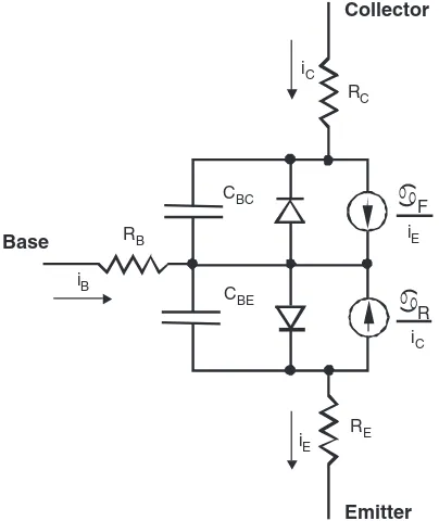
BJT (Bipolar junction transistor) Conducts collector current (in one direction) when sufficient base current is applied. The function applies to dc–dc circuits. Power BJTs have mostly been supplanted by FETs and IGBTs.
FET (Field effect transistor) Conducts drain current when sufficient gate voltage is applied. Power FETs (nearly always enhancement-mode MOSFETs) have a parallel connected reverse diode by virtue of their construction. Ratings from about 0.5 A to about 150 A and 20 V up to 1200 V. Switching times are fast, from 20 ns or less up to 200 ns. The function applies to dc–dc conversion, where the FET is in wide use, and to inverters.
IGBT (Insulated gate bipolar transistor) A special type of transistor that has the function of a BJT with its base driven by an FET. Faster than a BJT of similar ratings, and easy to use. Ratings from 10 A to more than 600 A, with voltages of 600 to 2500 V. The IGBT is popular in inverters from about 1 to 200 kW or more. It is found almost exclusively in power electronics applications.
SCR (Silicon-controlled rectifier) A thyristor that conducts like a diode after a gate pulse is applied. Turns off only when current becomes zero. Prevents current flow until a pulse appears. Ratings from 10 A up to more than 5000 A, and from 200 V up to 6 kV. Switching requires 1 to 200µs. Widely used for controlled rectifiers. The SCR is found almost exclusively in power electronics applications, and is the most common member of the thyristor family.
GTO (Gate turn-off thyristor) An SCR that can be turned off by sending a negative pulse to its gate terminal. Can substitute for transistors in applications above 200 kW or more. The ratings approach those of SCRs, and the speeds are similar as well.
TRIAC A semiconductor constructed to resemble two SCRs connected in reverse parallel. Ratings from 2 to 50 A and 200 to 800 V. Used in lamp dimmers, home appliances, and hand tools. Not as rugged as many other device types, but very convenient for many ac applications. IGCT (Integrated gate commutated thyristor) A combination device that includes a high-power thyristor and external electronics to control it. This
device is a member of a larger family of combination devices, in which multiple semiconductor chips packaged together perform a single power function. The IGCT provides a high-performance GTO function for power levels above 1 MW or more.
to high-power controllable rectifiers, they have been applied to all power-conversion applications.
Some of the features of the most common power semicon-ductors are listed in Table 1.1. The table shows a wide variety of speeds and rating levels. As a rule, faster speeds apply to lower ratings. For each device type, cost tends to increase both for faster devices and for devices with higher power-handling capacity.
Conducting direction and blocking behavior are fundamen-tally tied to the device type, and these basic characteristics constrain the choice of device for a given conversion function. Consider again a diode. It carries current in only one direc-tion and always blocks current in the other direcdirec-tion. Ideally, the diode exhibits no forward voltage drop or off-state leak-age current. Although an ideal diode lacks the many features of an ideal switch, it is an important switching device. Other real devices operate with polarity limits on current and voltage and have corresponding ideal counterparts. It is convenient to define a special type of switch to represent this behavior: the
restricted switch.
TABLE 1.2 The types of restricted switches
Action Device Quadrants Restricted switch symbol Device symbol
Carries current in one direction, blocks in the other (forward-conducting reverse-blocking)
Diode I
V
Carries or blocks current in one direction (forward-conducting forward-blocking)
BJT I
V
Carries in one direction or blocks in both directions (forward-conducting bidirectional-blocking)
GTO I
V
Carries in both directions, but blocks only in one direction (bidirectional-carrying forward-blocking)
FET I
V
Fully bidirectional Ideal switch I
V
The diode always permits current flow in one direction, while blocking flow in the other direction. It therefore represents a
forward-conducting reverse-blockingrestricted switch and oper-ates in one quadrant on a graph of device current versus. voltage. This function is automatic – the two diode terminals provide all the necessary information for switch action. Other restricted switches require a thirdgate terminal to determine their state. Consider the polarity possibilities given in Table 1.2. Additional functions such as bidirectional-conducting reverse-blocking can be obtained by reverse connection of one of the five types in the table.
The quadrant operation shown in the table indicates polarities. For example, the current in a diode will be posi-tive when on, and the voltage will be negaposi-tive when off. This means diode operation is restricted to the single quadrant com-prising the upper vertical (current) axis and the left horizontal (voltage) axis. Other combinations appear in the table. Sym-bols for restricted switches can be built up by interpreting the diode’s triangle as the current-carrying direction and the bar as the blocking direction. Five types of symbols can be drawn as shown in Table 1.2. These symbols are used infrequently, but are useful for showing the polarity behavior of switching devices. A circuit drawn with restricted switches represents an idealized power converter.
Restricted switch concepts guide the selection of devices. For example, consider an inverter intended to deliver ac load current from a dc voltage source. A switch matrix built to perform this function must be able to manipulate ac current
and dc voltage. Regardless of the physical arrangement of the matrix, we would expect bidirectional-conducting forward-blocking switches to be useful for this conversion. This is a correct result: modern inverters operating from dc volt-age sources are built with FETs or with IGBTs packvolt-aged with reverse-parallel diodes. As new power devices are introduced to the market, it is straightforward to determine what types of converters will use them.
1.5.4 Resolving the Software Problem –
Switching Functions
The physical m×n switch matrix can be associated with a mathematicalm×n switch state matrix. Each element of this matrix, called aswitching function, shows whether the corre-sponding physical device is on or off.
DEFINITION Aswitching function,q(t), has a value of 1 when the corresponding physical switch is on and 0 when it is off. Switching functions are discrete-valued functions of time, and control of switching devices can be represented with them.
![FIGURE 1.2General system for electric power conversion. (From [2],](https://thumb-ap.123doks.com/thumbv2/123dok/3286532.1747038/21.612.65.280.58.269/figure-general-electric-power-conversion.webp)